EP1245925B1 - Neigungsmessvorrichtung - Google Patents
Neigungsmessvorrichtung Download PDFInfo
- Publication number
- EP1245925B1 EP1245925B1 EP02252135A EP02252135A EP1245925B1 EP 1245925 B1 EP1245925 B1 EP 1245925B1 EP 02252135 A EP02252135 A EP 02252135A EP 02252135 A EP02252135 A EP 02252135A EP 1245925 B1 EP1245925 B1 EP 1245925B1
- Authority
- EP
- European Patent Office
- Prior art keywords
- light
- pattern
- detecting device
- reflection
- tilt detecting
- Prior art date
- Legal status (The legal status is an assumption and is not a legal conclusion. Google has not performed a legal analysis and makes no representation as to the accuracy of the status listed.)
- Expired - Lifetime
Links
- 239000007788 liquid Substances 0.000 claims description 107
- 230000003287 optical effect Effects 0.000 claims description 48
- 230000005540 biological transmission Effects 0.000 claims description 13
- 230000010287 polarization Effects 0.000 claims description 13
- 239000012528 membrane Substances 0.000 claims description 2
- 238000010586 diagram Methods 0.000 description 10
- 239000000463 material Substances 0.000 description 4
- 238000005259 measurement Methods 0.000 description 4
- 230000000712 assembly Effects 0.000 description 3
- 238000000429 assembly Methods 0.000 description 3
- 230000007613 environmental effect Effects 0.000 description 3
- 229920000535 Tan II Polymers 0.000 description 2
- 229920002545 silicone oil Polymers 0.000 description 2
- 239000000758 substrate Substances 0.000 description 2
- 230000003247 decreasing effect Effects 0.000 description 1
- 230000001419 dependent effect Effects 0.000 description 1
- 238000001514 detection method Methods 0.000 description 1
- 238000006073 displacement reaction Methods 0.000 description 1
- 230000000694 effects Effects 0.000 description 1
- QSHDDOUJBYECFT-UHFFFAOYSA-N mercury Chemical compound [Hg] QSHDDOUJBYECFT-UHFFFAOYSA-N 0.000 description 1
- 229910052753 mercury Inorganic materials 0.000 description 1
- 239000004065 semiconductor Substances 0.000 description 1
Images



Classifications
-
- G—PHYSICS
- G01—MEASURING; TESTING
- G01C—MEASURING DISTANCES, LEVELS OR BEARINGS; SURVEYING; NAVIGATION; GYROSCOPIC INSTRUMENTS; PHOTOGRAMMETRY OR VIDEOGRAMMETRY
- G01C15/00—Surveying instruments or accessories not provided for in groups G01C1/00 - G01C13/00
-
- G—PHYSICS
- G01—MEASURING; TESTING
- G01C—MEASURING DISTANCES, LEVELS OR BEARINGS; SURVEYING; NAVIGATION; GYROSCOPIC INSTRUMENTS; PHOTOGRAMMETRY OR VIDEOGRAMMETRY
- G01C9/00—Measuring inclination, e.g. by clinometers, by levels
- G01C9/02—Details
- G01C9/06—Electric or photoelectric indication or reading means
-
- G—PHYSICS
- G01—MEASURING; TESTING
- G01C—MEASURING DISTANCES, LEVELS OR BEARINGS; SURVEYING; NAVIGATION; GYROSCOPIC INSTRUMENTS; PHOTOGRAMMETRY OR VIDEOGRAMMETRY
- G01C9/00—Measuring inclination, e.g. by clinometers, by levels
- G01C9/18—Measuring inclination, e.g. by clinometers, by levels by using liquids
- G01C9/20—Measuring inclination, e.g. by clinometers, by levels by using liquids the indication being based on the inclination of the surface of a liquid relative to its container
Definitions
- the present invention relates to a tilt detecting device using a liquid member to form a free liquid surface.
- the present applicant proposed a tilt detecting device using a free liquid surface and a survey instrument comprising the tilt detecting device in JP-A-11-118482 ( U.S. Patent No.6,204,498 ).
- a first light source 1 e.g. an LED, for emitting a light beam in a horizontal direction is provided.
- a first condenser lens 2 On an optical axis of the first light source 1, a first condenser lens 2, a first pattern 3, a second condenser lens 4, and a first half-mirror 5 are arranged.
- a liquid member 6 On an optical axis of a reflection light from the first half-mirror 5, a liquid member 6 is disposed, and the liquid member 6 is accommodated in a container 7 so that a free liquid surface 6a is formed.
- a liquid having adequate viscosity e.g. silicone oil, is used.
- the first light source 1 and the free liquid surface 6a of the liquid member 6 are arranged at conjugate positions.
- the light beam reflected by the first half-mirror 5 is reflected by the free liquid surface 6a and passes through the first half-mirror 5.
- a third condenser lens 9 and a photodetection means 11 are arranged on an optical axis of the transmission light from the first half-mirror 5.
- the light beam emitted from the first light source 1 is turned to a parallel beam by the first condenser lens 2.
- the light beam passing through the first pattern 3 passes through the condenser lens 4 and is reflected upward by the first half-mirror 5 and is reflected by the free liquid surface 6a.
- the beam is received by the photodetection means 11.
- the second condenser lens 4 and the third condenser lens 9 form an image of the first pattern 3 on the photodetection means 11.
- the result of the photodetection of the photodetection means 11 is inputted to an arithmetic processing unit 13.
- a reference position is set on the photodetection means 11.
- the value L of the pattern image with respect to the reference position can be calculated, and tilting ⁇ of the tilt detecting device itself can be further obtained by inverse calculation.
- the reference position is set on the photodetection element, and there is possibility that the reference position is changed over time with respect to a main unit of the surveying instrument which comprises the tilt detecting device. Also, the photodetection element may be moved due to the change of environmental temperature. In such case, there has been a problem that the reference position is displaced, and error may occur in the tilt detection.
- a unit having a function suitable for the work is removably mounted in some cases. In these cases, only tilting of an assembly where the tilt detecting device is mounted can be detected by the conventional type tilt detecting device, and tilting of the unit remains indefinite.
- United States Patent No. 5392112 describes an inclination angle metering apparatus.
- a beam from a light source is split into two beams by a half-mirror provided in a light path between the light source and the surface of a liquid.
- One beam is reflected by the liquid surface and falls on a line or area sensor.
- the other beam falls on the line sensor without being reflected by the liquid surface.
- An inclination angle to the liquid surface is determined based on the incident position of one beam with respect to the incident position of the other beam.
- United States Patent No. 2460836 describes a level device employing a light reflecting liquid surface as a horizontal reference surface.
- the level device comprises a cup-shaped container having a plane bottom surface and a plane top surface which is parallel to the bottom surface in the container is a quantity of fluent material such as mercury.
- An incident beam is reflected from the top surface and strikes a screen at a first point.
- a second incident beam is reflected from the top surface of the fluent material and strikes the screen at a second point. The distance between the first and second point is used to determine the angle of the device relative to the horizontal plane.
- a tilt detecting device as defined in claim 1 is provided.
- Fig. 1 the same component as shown in Fig. 11 is referred by the same symbol.
- a first light source 1 e.g. an LED, for emitting a light beam in a horizontal direction is provided.
- a first condenser lens 2 On an optical axis of the first light source 1, a first condenser lens 2, a first pattern 3, a second condenser lens 4, and a first half-mirror 5 are arranged.
- a liquid member 6 On an optical axis of a reflection light from the first half-mirror 5, a liquid member 6 is disposed, and the liquid member 6 is accommodated in a container (not shown) so that a free liquid surface 6a is formed.
- a liquid having adequate viscosity e.g. silicone oil
- the first light source 1 and the free liquid surface 6a may be arranged at positions conjugate to each other. By arranging these components at conjugate positions, a reflection area on the free liquid surface 6a is minimized, and this makes it possible to minimize error caused by surface tension of the liquid member 6. Further, it provides an effect to reduce a volume of the liquid member 6.
- the first light source 1, the first condenser lens 2, the first pattern 3, the second condenser lens 4, and the first half-mirror 5, etc. make up together a free liquid surface light projecting system 8.
- the light beam reflected by the first half-mirror 5 is reflected by the free liquid surface 6a and passes through the first half-mirror 5.
- a second half-mirror 15 On an optical axis 10 of the transmission light from the first half-mirror 5, a second half-mirror 15, a third condenser lens 9, and a photodetection means 11 are arranged.
- the photodetection means 11 As the photodetection means 11, a CCD area sensor is used, for instance.
- a second light source 17 which has a projection light optical axis in parallel to the transmission light optical axis 10 of the first half-mirror 5.
- a fourth condenser lens 18, a second pattern 19, a fifth condenser lens 20, and a third half-mirror 21 are arranged, and the third half-mirror 21 faces to the second half-mirror 15.
- a reflection member 22 is disposed at a position perpendicular to the transmission light optical axis.
- the reflection member 22 is mounted on a structural member such as a housing of the tilt detecting device. Therefore, when the tilt detecting device itself is placed accurately at a horizontal position, a reflection surface of the reflection member 22 is at a horizontal position.
- the second light source 17, the fourth condenser lens 18, the second pattern 19, the fifth condenser lens 20, and the third half-mirror 21, etc. make up together a fixed reflection member light projecting system 24.
- the first half-mirror 5, the second half-mirror 15, the third half-mirror 21, the third condenser lens 9, and the photodetection means 11, etc. make up together a photodetection optical system 12.
- the light beam emitted from the first light source 1 is turned to a parallel beam by the first condenser lens 2.
- the beam passes through the first pattern 3 and the second condenser lens 4, the beam is reflected by the first half-mirror 5. Further, the beam is reflected by the free liquid surface 6a.
- the beam is received by the photodetection means 11. That is, a first pattern image 3a (not shown) of the first pattern 3 is formed on the photodetection means 11 by the third condenser lens 9.
- the light beam emitted from the second light source 17 is turned to a parallel beam and the beam passes through the second pattern 19. Further, the beam passes through the fifth condenser lens 20 and the third half-mirror 21 and is reflected by the reflection member 22. The beam is then reflected by the third half-mirror 21 and the second half-mirror 15 and is received by the photodetection means 11 via the third condenser lens 9. That is, a second pattern image 19a (not shown) of the second pattern 19 is also formed on the photodetection means 11 by the third condenser lens 9.
- a reflection light optical axis 23 of the reflection light from the reflection member 22 as reflected by the second half-mirror 15 is aligned with the transmission light optical axis 10 when the transmission light optical axis 10 is in a vertical direction. Therefore, the first pattern image 3a of the first pattern 3 is aligned with the second pattern image 19a of the second pattern 19.
- the transmission light optical axis 10 is the optical axis of the light reflected by the free liquid surface 6a. Therefore, when the tilt detecting device itself is tilted, the free liquid surface 6a of the liquid member 6 is relatively tilted with respect to the tilt detecting device itself. As a result, the reflection light optical axis 23 is deflected with respect to the incident light optical axis.
- the reflection light optical axis is deflected at an angle of 2n ⁇ where n is a refractive index of the liquid member 6.
- the first pattern image 3a is moved from the reference position by an amount of f x tan (2n ⁇ ) on the photodetection means 11.
- the projection light optical axis of the fixed reflection member light projecting system 24 is fixed with respect to the tilt detecting device itself, and the reflection member 22 is also fixed with respect to the tilt detecting device itself. Therefore, a light receiving position of the light beam reflected by the reflection member 22 on the photodetection means 11 (i.e. a position of the second pattern image 19a) is fixed regardless of tilting of the tilt detecting device itself.
- a deviation of the first pattern image 3a from the second pattern image 19a can be detected as an amount of movement L of the first pattern image 3a.
- the deviation between the first pattern image 3a and the second pattern image 19a is calculated based on a photodetection signal from the photodetection means 11. Further, based on the deviation, a tilting amount and a tilting direction are calculated.
- the second pattern image 19a from the photodetection optical system 12 is used as a reference.
- the reflection light optical axis 23 of the light from the reflection member 22 may not necessarily be aligned with or may not be parallel to the reflection light optical axis 23 of the light from the free liquid surface 6a. It would suffice if the fixed second pattern image 19a is formed on the photodetection means 11 regardless of the tilting of the tilt detecting device itself. Further, when the tilt detecting device itself is at the horizontal position, the first pattern image 3a and the second pattern image 19a may not necessarily be aligned with each other on the photodetection means 11, and the deviation amount between these two pattern images should be used as a correction value for calculation.
- an opaque pattern is formed on a transparent substrate or a pattern is perforated on an opaque substrate, and a darkfield pattern is formed.
- the first pattern 3 is shown in Fig. 2 , for instance, and the second pattern 19 is shown in Fig. 3 , for instance.
- the first pattern 3 comprises a row of slits where slits 26 are formed by perforation with predetermined equal spacing (pitch) p. It is supposed now that a direction of the row of slits is in an X-axis direction, for instance.
- Each of the slits 26 is designed in an oblong triangular shape with its width gradually reduced in one direction, and its longitudinal direction is aligned with a Y-axis direction.
- the second pattern 19 is formed by perforating slits 27a and 27b in a cross-shape.
- the slit 27a runs in parallel to the Y-axis direction
- the slit 27b is in parallel to the X-axis direction.
- the slit 27b crosses the slit 26.
- the free liquid surface 6a is relatively tilted with respect to the tilt detecting device itself, and it is moved on the photodetection means 11 by an amount of f ⁇ tan (2n ⁇ ).
- a horizontal reference position i.e. a distance dx between the slit 27a on the photodetection means 11 and the starting pattern should be measured.
- a phase difference ⁇ from the horizontal reference position with respect to the pitch spacing is calculated by Fourier transform of the output of the photodetection means 11. ⁇ ⁇ p / 2 ⁇ ⁇
- the distance shorter than the pitch spacing can be measured with high accuracy.
- the total distance can be calculated.
- the amount of movement (tilt angle) in the Y-axis direction is calculated from the triangular shape of the slit 26 with its width gradually changed.
- the slit 27b is projected so that it crosses the slit 26 in the X-axis direction and the slit 27b is not moved. Therefore, when the tilt detecting device itself is tilted in the Y-axis direction, the width of the triangular slit 26 which the slit 27b crosses is changed. The amount of the change is proportional to the tilt angle in the Y-axis direction.
- the arithmetic processing unit 13 can calculate the tilt angle in the Y-axis direction based on the change of the width.
- the tilting in the Y-axis direction can be calculated from the equation (1).
- the shape of the slit 26 with its width gradually changing is not limited to the triangular shape.
- the slit of any shape may be used so far as the width is changed and correspondence to the tilting is set.
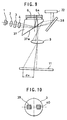
- a beam splitter 28 having a semi-transmitting surface 28a is used as the first half-mirror 5.
- the beam splitter 28 has a surface 28b tilted with respect to a transmission light, which passes through the semi-transmitting surface 28a, among the light beam coming from the first light source 1.
- the surface 28b reflects the light beam passing through the semi-transmitting surface 28a by deflecting the light beam from the incident light optical axis, and a reflection light from the surface 28b does not enter the photodetection means 11. For this reason, noise is decreased in the light beam received by the photodetection means 11.
- an optical member 29 which optically integrates the semi-transmitting surface 28a with the liquid member 6.
- the optical member 29 has a refractive index equal or similar to the refractive index of the liquid member 6. For this reason, reflection and refraction on a boundary surface between the liquid member 6 and the optical member 29 are prevented. This makes it possible to prevent generation of an unnecessary reflection light, and measurement can be made with high accuracy.
- an anti-reflection membrane using a medium which has a refractive index between the refractive index of the optical member 29 and that of the liquid member 6 may be provided on a surface where the optical member 29 comes into contact with the liquid member 6, and the reflection light at the boundary surface can be reduced.
- the liquid member 6 is sealed in a container 31.
- the photodetection means 11 receives the reflection light reflected by the free liquid surface 6a. Most of the light beam (90% or more) entering the liquid member 6 pass through the free liquid surface 6a. As a result, compared with the light amount of the light reflected by the free liquid surface 6a, a light amount of the reflection light reflected by the upper inner surface 31a of the container 31 is not a negligible value. When the upper inner surface 31a is tilted, the reflection light is deflected by the upper inner surface 31a, and it is deviated from the reflection light reflected by the free liquid surface 6a, and the reflection light from the upper inner surface 31a is not received by the photodetection means 11.
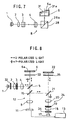
- a polarization member is added to the arrangement shown in Fig. 1 , and transmission and reflection efficiency is improved in the first half-mirror 5, the second half-mirror 15, and the third half-mirror 21 in the embodiment of Fig. 1 .
- a first polarizing plate 32 is disposed between the first light source 1 and the first condenser lens 2, and a first ⁇ /4 polarization member 33 is arranged between the liquid member 6 and the first half-mirror 5, i.e. in a common optical path for incidence and reflection of the light beam.
- a second polarizing plate 34 is arranged between the second light source 17 and the fourth condenser lens 18, and a second ⁇ /4 polarization member 35 is disposed between the reflection member 22 and the third half-mirror 21.
- a polarization beam splitter is used as each of the first half-mirror 5, the second half-mirror 15, and the third half-mirror 21.
- the first half-mirror 5, the second half-mirror 15, and the third half-mirror 21 reflect an S-polarized light and allow a P-polarized light to pass.
- a light source such an LED, etc. is used so as not to define polarization.
- the light beam emitted from the first light source 1 is turned to an S-polarized linearly polarized light by the first polarizing plate 32 and enters the first half-mirror 5.
- the first half-mirror 5 serves as a polarization beam splitter, which reflects the S-polarized light and allows the P-polarized light to pass. Therefore, the light beam from the first light source 1 is reflected toward the liquid member 6.
- the light beam reflected by the liquid member 6 passes through the first ⁇ /4 polarization member 33 twice, and the light beam is turned to a P-polarized linearly polarized light. Therefore, the light beam passes through the first half-mirror 5 and the second half-mirror 15 and is received by the photodetection means 11.
- the light beam emitted from the second light source 17 is a P-polarized linearly polarized light, and the light beam passes through the third half-mirror 21 and is reflected by the reflection member 22.
- the light beam passes through the second ⁇ /4 polarization member 35 twice, and the reflection light is turned to an S-polarized light. Therefore, the light beam is reflected by the third half-mirror 21 and the second half-mirror 15 and is received by the photodetection means 11.
- reflection and transmission are performed using polarization, and this contributes to the improvement of efficiency.
- the light receiving amount on the photodetection means 11 is increased, and this leads to the improvement of measurement accuracy.
- the first polarizing plate 32 and the second polarizing plate 34 can be omitted.
- the functions of the first light source 1 and the second light source 17 in the first embodiment shown in Fig. 1 are fulfilled by a single light source.
- the first condenser lens 2, the first pattern 3, and the second condenser lens 4 are sequentially arranged.
- a beam splitter 37 is positioned to face the second condenser lens 4, and the liquid member 6 sealed in a container (not shown) is disposed on the upper surface of the beam splitter 37.
- a reflection means 38 such as a mirror is arranged on an opposite side of the second condenser lens 4 with the beam splitter 37 between the reflection means 38 and the second condenser lens 4, and a reflection member 22 is disposed to face a reflection surface of the reflection means 38.
- the reflection member 22 is mounted on a fixed structural member such as a housing of the tilt detecting device itself. When the tilt detecting device itself is set at the horizontal position, the reflection surface is aligned with the horizontal direction.
- the third condenser lens 9, and further, the photodetection means 11 are arranged to face the free liquid surface 6a of the liquid member 6.
- Patterns 39 and 40 are formed on each side of the first pattern 3 with the optical axis therebetween.
- the optical arrangement is designed in such manner that the light beam passing through the pattern 39 is directed toward the liquid member 6 and the light beam passing through the pattern 40 is directed toward the reflection member 22.
- the first light source 1, the first condenser lens 2, the first pattern 3, the second condenser lens 4, and the beam splitter 37 make up together a free liquid surface light projecting system.
- the first light source 1, the first condenser lens 2, the first pattern 3, the second condenser lens 4, the beam splitter 37, and the reflection means 38 make up together a fixed reflection member light projecting system.
- the beam splitter 37 and the third condenser lens 9 make up together a photodetection optical system.
- the light beam emitted from the first light source 1 is turned to a parallel beam by the first condenser lens 2, and the parallel beam passes through the first pattern 3.
- the light beam passing through the pattern 39 is reflected by the semi-transmitting surface 37a of the beam splitter 37 and reaches the free liquid surface 6a.
- the first pattern 3 and the free liquid surface 6a are at positions conjugate to each other, and an image of the pattern 39 is formed on the free liquid surface 6a.
- the light beam reflected by the free liquid surface 6a and passing through the semi-transmitting surface 37a forms an image on the photodetection means 11 by the third condenser lens 9.
- the light beam passing through the pattern 40 passes through the semi-transmitting surface 37a and is reflected and deflected by the reflection means 38 and is directed toward the reflection member 22. Further, the light beam reflected by the reflection member 22, the reflection means 38 and the semi-transmitting surface 37a forms an image on the photodetection means 11 by the third condenser lens 9.
- the image of the pattern 39 reflected by the free liquid surface 6a and the image of the pattern 40 reflected by the reflection member 22 are formed at the same time.
- the free liquid surface 6a is relatively tilted with respect to the tilt detecting device itself because the free liquid surface is maintained in the horizontal direction.
- the optical system as described above is integrated with and fixed on the tilt detecting device itself, and the photodetecting position of the pattern 39 on the photodetection means 11 is moved in association with the tilting.
- the pattern 40 reflected by the reflection member 22 is not changed even when the tilt detecting device itself is tilted, and the photodetecting position on the photodetection means 11 is not changed. Therefore, by detecting displacement of the positions of the images of the patterns 39 and 40, it is possible to obtain tilt angle of the tilt detecting device itself.
- the reflection member 22 when the reflection member 22 is mounted on an assembly or a component which is removably mounted on the tilt detecting device itself, and if it is wanted to set the assembly or the component in a horizontal position, the reflection member 22 should be made parallel to the free liquid surface 6a. Therefore, if it is supposed that deviation between the photodetecting position of the pattern 39 received at the photodetection means 11 and photodetecting position of the pattern 40 is 0, the free liquid surface 6a and the reflection member are in parallel to each other. Thus, leveling operation should be performed on the tilt detecting device itself in such direction that the deviation will be 0. Accordingly, when a plurality of assemblies and components are removably mounted on the tilt detecting device, the entire system can be used with horizontality compensated with high accuracy.
- the tilt detecting device for detecting tilt by a reflection light from a free liquid surface comprises a photodetection element, a liquid member for forming the free liquid surface, a fixed reflection member fixed on a structural member, a free liquid surface light projecting system for projecting a light toward the liquid member, a fixed reflection member light projecting system for projecting a light toward the fixed reflection member, a photodetection optical system for guiding the reflection light from the free liquid surface of the liquid member and a reflection light from the fixed reflection member toward the photodetection element, and an arithmetic processing unit for calculating deviation based on two reflection images received by the photodetection element and tilting of the device itself.
Landscapes
- Physics & Mathematics (AREA)
- Engineering & Computer Science (AREA)
- General Physics & Mathematics (AREA)
- Radar, Positioning & Navigation (AREA)
- Remote Sensing (AREA)
- Length Measuring Devices By Optical Means (AREA)
Claims (10)
- Neigungsdetektionsvorrichtung zur Detektion einer Neigung durch ein Reflexionslicht von einer freien Flüssigkeitsoberfläche (6a), mit einem Fotodetektionselement (11) in Form eines Flächensensors, einem Flüssigkeitselement zur Bildung der freien Flüssigkeitsoberfläche (6a), einem an einem Strukturelement befestigten festen Reflexionselement (22), einem ersten zweidimensionalen Muster (3), einem vom ersten zweidimensionalen Muster (3) unterschiedlichen zweiten zweidimensionalen Muster (19), einem Projektionssystem (8) für Licht bezüglich der freien Flüssigkeitsoberfläche zum Projizieren von Licht durch das erste zweidimensionale Muster (3) zum Flüssigkeitselement (6), einem Projektionssystem (24) für Licht bezüglich des festen Reflexionselements zum Projizieren eines Lichts durch das zweite zweidimensionale Muster (19) zum festen Reflexionselement (22), einem optischen Fotodetektionssystem (12) zum Leisten des von der freien Flüssigkeitsoberfläche (6a) des Flüssigkeitselements (6) reflektierten Musterbilds und des vom festen Reflexionselement (22) reflektierten Musterbilds zum Fotodetektionselement (11) und zum Projizieren der reflektierten Musterbilder, so dass die Musterbilder zueinander ausgerichtet sind, und mit einer arithmetischen Verarbeitungseinheit (13) zum Berechnen der Abweichung in zwei Dimensionen auf Basis des auf das Fotodetektionselement (11) projizierten ersten und zweiten zweidimensionalen Reflexionsmusterbilds und zum Berechnen eines Neigungswinkels und einer Neigungsrichtung aus der Abweichung.
- Neigungsdetektionsvorrichtung nach Anspruch 1, wobei das erste Muster (3) im Projektionssystem (8) für Licht bezüglich der freien Flüssigkeitsoberfläche vorgesehen ist und das zweite Muster (19) im Projektionssystem (24) für Licht bezüglich des festen Reflexionselements vorgesehen ist, wobei das erste Muster (3) und das zweite Muster (19) Dunkelfeldmuster sind.
- Neigungsdetektionsvorrichtung nach Anspruch 1, wobei das Projektionssystem (8) für Licht bezüglich der freien Flüssigkeitsoberfläche und das Projektionssystem (24) für Licht bezüglich des festen Reflexionselements linear polarisierte Lichtstrahlen derselben Phase projizieren, wobei ein λ/4-Polarisationselement (33) in einem gemeinsamen optischen Pfad für den Einfall und die Reflexion des Lichts zu bzw. von dem Flüssigkeitselement (6) vorgesehen ist und ein λ/4-Polarisationselement (35) in einem gemeinsamen Strahlengang für den Einfall und die Reflexion des Lichts zu bzw. von dem festen Reflexionselement (22) vorgesehen ist, und wobei das optische Fotodetektionssystem (12) ein optisches Polarisationselement (5, 15, 21) aufweist, welches nur den Durchtritt des Reflexionslichts vom Flüssigkeitselement (6) und vom fixen Reflexionselement (22) gestattet, und wobei vorzugsweise eine Polarisationsrichtung des projizierten Lichtstrahls durch eine Polarisationsplatte (32) bestimmt wird.
- Neigungsdetektionsvorrichtung nach Anspruch 1, wobei das Projektionssystem (8) für Licht bezüglich der freien Flüssigkeitsoberfläche, das Projektionssystem (24) für Licht bezüglich des festen Reflexionselements und das optische Fotodetektionssystem (12) jeweils einen Strahlteiler (37) aufweisen und der Strahlteiler (37) eine Fläche (37a) hat, die in Bezug auf ein durch eine halb-durchlässige Fläche hindurchtretendes Transmissions-Licht geneigt ist.
- Neigungsdetektionsvorrichtung nach Anspruch 1, wobei das Projektionssystem (8) für Licht bezüglich der freien Flüssigkeitsoberfläche und das Projektionssystem (24) für Licht bezüglich des festen Reflexionselements eine gemeinsame Lichtquelle (1) und einen Strahlteiler (37) zum Teilen des Lichtstrahls von der Lichtquelle (1) in einen zum Flüssigkeitselement (6) gerichteten Lichtstrahl und einen zum festen Reflexionselement (22) gerichteten Lichtstrahl aufweisen.
- Neigungsdetektionsvorrichtung nach Anspruch 5, wobei ein Muster (3) vorgesehen ist, welches so angeordnet ist, dass der Lichtstrahl von der gemeinsamen Lichtquelle (1) hindurchtreten kann, und das Muster (3) weiters ein erstes Mustertor (39), wo der zum Flüssigkeitselement gerichtete Lichtstrahl hindurchtreten kann, und ein zweites Mustertor (40) aufweist, wo der zum festen Reflexionselement (22) gerichtete Lichtstrahl hindurchtreten kann.
- Neigungsdetektionsvorrichtung nach Anspruch 1, wobei das Flüssigkeitselement (6) in einem Behälter (7) untergebracht ist und eine obere Fläche des Behälters (7) in Bezug auf das durch die freie Flüssigkeitsoberfläche (6a) hindurchtretende Transmissions-Licht geneigt ist.
- Neigungsdetektionsvorrichtung nach Anspruch 1, wobei das Projektionssystem (8) für Licht bezüglich der freien Flüssigkeitsoberfläche einen Halbspiegel (5, 28) zur Reflexion des Lichtstrahls zum Flüssigkeitselement (6) und zur Ermöglichung des Durchtritts des Reflexionslichts vom Flüssigkeitselement (6) aufweist, und wobei der Halbspiegel (5, 28) und das Flüssigkeitselement (6) optisch miteinander integriert sind.
- Neigungsdetektionsvorrichtung nach Anspruch 8, wobei der Halbspiegel (5, 28) und das Flüssigkeitselement (6) über ein optisches Element (29) optisch miteinander integriert sind.
- Neigungsdetektionsvorrichtung nach Anspruch 9, wobei ein Brechungsindex des Flüssigkeitselements (6) annähernd gleich einem Brechungsindex des optischen Elements (29) ist, oder wobei eine Antireflexionsmembran zwischen dem Flüssigkeitselement (6) und dem optischen Element (29) vorgesehen ist.
Applications Claiming Priority (2)
| Application Number | Priority Date | Filing Date | Title |
|---|---|---|---|
| JP2001094003 | 2001-03-28 | ||
| JP2001094003A JP4653898B2 (ja) | 2001-03-28 | 2001-03-28 | 傾斜検出装置 |
Publications (3)
| Publication Number | Publication Date |
|---|---|
| EP1245925A2 EP1245925A2 (de) | 2002-10-02 |
| EP1245925A3 EP1245925A3 (de) | 2002-11-27 |
| EP1245925B1 true EP1245925B1 (de) | 2010-03-17 |
Family
ID=18948270
Family Applications (1)
| Application Number | Title | Priority Date | Filing Date |
|---|---|---|---|
| EP02252135A Expired - Lifetime EP1245925B1 (de) | 2001-03-28 | 2002-03-25 | Neigungsmessvorrichtung |
Country Status (4)
| Country | Link |
|---|---|
| US (1) | US6649927B2 (de) |
| EP (1) | EP1245925B1 (de) |
| JP (1) | JP4653898B2 (de) |
| DE (1) | DE60235668D1 (de) |
Families Citing this family (7)
| Publication number | Priority date | Publication date | Assignee | Title |
|---|---|---|---|---|
| JP4712212B2 (ja) * | 2001-03-28 | 2011-06-29 | 株式会社トプコン | レーザ照準装置 |
| US6892464B2 (en) * | 2002-03-13 | 2005-05-17 | Kabushiki Kaisha Topcon | Laser sighting device |
| JP4267971B2 (ja) * | 2003-06-13 | 2009-05-27 | 株式会社トプコン | レーザ光線照準装置及び光軸補償方法 |
| JP4282432B2 (ja) | 2003-10-14 | 2009-06-24 | 株式会社トプコン | 回転レーザ装置の受光装置 |
| US20070076171A1 (en) * | 2005-09-20 | 2007-04-05 | Fasen Donald J | Wobulator position sensing system and method |
| CN102445187B (zh) * | 2010-10-12 | 2013-11-13 | 上海微电子装备有限公司 | 一种水平测量装置 |
| JP6632128B2 (ja) * | 2016-01-18 | 2020-01-15 | 株式会社トプコン | 液面反射式傾斜センサにおける容器の設計方法、該容器を有する傾斜センサ、及び該容器を有する傾斜センサの生産方法 |
Family Cites Families (16)
| Publication number | Priority date | Publication date | Assignee | Title |
|---|---|---|---|---|
| US2460836A (en) * | 1946-06-04 | 1949-02-08 | American Instr Co Inc | Level device employing a light reflecting liquid surface as a horizontal refrence surface |
| JPS5899712A (ja) * | 1981-12-09 | 1983-06-14 | Tokyo Optical Co Ltd | 傾斜角測定装置 |
| JPH0619273B2 (ja) * | 1986-05-23 | 1994-03-16 | 株式会社ソキア | 傾斜角検出センサ |
| SU1451541A1 (ru) * | 1987-01-12 | 1989-01-15 | А.А.Жмудь и В.М.Тиссен | Устройство дл измерени углов наклона объекта |
| JP2913984B2 (ja) * | 1992-03-11 | 1999-06-28 | 株式会社ニコン | 傾斜角測定装置 |
| JP3226970B2 (ja) * | 1992-07-09 | 2001-11-12 | 株式会社トプコン | レーザ測量機 |
| JP3100478B2 (ja) * | 1992-10-27 | 2000-10-16 | 株式会社トプコン | 往復レーザ走査システムを有するレーザ回転照射装置 |
| JPH09236435A (ja) * | 1995-12-29 | 1997-09-09 | Nikon Corp | 自動傾き補正装置及びこの装置を用いた傾き検出装置 |
| DE19603179C1 (de) * | 1996-01-30 | 1997-02-06 | Zeiss Carl Jena Gmbh | Interferometrischer Neigungsmesser |
| JPH09210687A (ja) * | 1996-01-31 | 1997-08-12 | Topcon Corp | レーザレベル装置 |
| DE19610941C2 (de) * | 1996-03-20 | 1998-10-15 | Zeiss Carl Jena Gmbh | Zweiachsiger Neigungsmesser und Verfahren zur Neigungsmessung |
| JP3673954B2 (ja) | 1996-04-17 | 2005-07-20 | 株式会社トプコン | 傾斜センサ及びこれを使用した測量機 |
| JP3787736B2 (ja) * | 1997-10-08 | 2006-06-21 | 株式会社トプコン | 傾斜センサ |
| JP4074967B2 (ja) * | 1998-03-15 | 2008-04-16 | 株式会社トプコン | レーザー照射装置 |
| US6473714B1 (en) * | 1998-09-29 | 2002-10-29 | Kabushiki Kaisha Topcon | Inclination measuring apparatus |
| JP4243695B2 (ja) * | 1998-09-29 | 2009-03-25 | 株式会社トプコン | 位置測定装置及びこれを使用した測量機 |
-
2001
- 2001-03-28 JP JP2001094003A patent/JP4653898B2/ja not_active Expired - Fee Related
-
2002
- 2002-03-04 US US10/090,248 patent/US6649927B2/en not_active Expired - Lifetime
- 2002-03-25 EP EP02252135A patent/EP1245925B1/de not_active Expired - Lifetime
- 2002-03-25 DE DE60235668T patent/DE60235668D1/de not_active Expired - Lifetime
Also Published As
| Publication number | Publication date |
|---|---|
| JP2002286448A (ja) | 2002-10-03 |
| US20020139940A1 (en) | 2002-10-03 |
| EP1245925A2 (de) | 2002-10-02 |
| DE60235668D1 (de) | 2010-04-29 |
| JP4653898B2 (ja) | 2011-03-16 |
| EP1245925A3 (de) | 2002-11-27 |
| US6649927B2 (en) | 2003-11-18 |
Similar Documents
| Publication | Publication Date | Title |
|---|---|---|
| US6675489B2 (en) | Laser sighting device | |
| US6295174B1 (en) | Reflective prism device | |
| JP3119715B2 (ja) | 2軸式傾斜測定装置 | |
| JP2913984B2 (ja) | 傾斜角測定装置 | |
| EP1067363B1 (de) | Vermessungssystem | |
| US6892464B2 (en) | Laser sighting device | |
| KR20110118706A (ko) | 비표지 바이오센서들의 조명 및 검출을 위한 효율적인 광학 배열 및 비표지 이미징에서 간섭 무늬들을 감소시키기 위한 방법 | |
| US6204498B1 (en) | Inclination sensor and surveying instrument using the same | |
| JPH10239051A (ja) | 傾斜角測定装置 | |
| EP1245925B1 (de) | Neigungsmessvorrichtung | |
| US7259842B2 (en) | Optical inclinometer | |
| CN100520295C (zh) | 光学测斜仪 | |
| JP2005529323A5 (de) | ||
| EP0989387B1 (de) | Laservermessungsinstrument | |
| JPH0345322B2 (de) | ||
| JP3120885B2 (ja) | 鏡面の測定装置 | |
| JP4074971B2 (ja) | 傾斜設定回転レーザー装置 | |
| JP2000028398A (ja) | 光学式エンコーダ装置 | |
| JPH04324923A (ja) | 投影露光装置 | |
| JPH03218442A (ja) | 示差屈折率計 | |
| JP2789414B2 (ja) | 微小傾斜角検出装置 | |
| JP2992943B2 (ja) | 微小傾斜角検出装置 | |
| CN119986957B (zh) | 一种适用于半透明晶圆的自动对焦系统和厚度测量系统 | |
| US20060226335A1 (en) | Apparatus and a method for the determination of the focal distance | |
| JP2001281098A (ja) | レンズメータ |
Legal Events
| Date | Code | Title | Description |
|---|---|---|---|
| PUAI | Public reference made under article 153(3) epc to a published international application that has entered the european phase |
Free format text: ORIGINAL CODE: 0009012 |
|
| AK | Designated contracting states |
Kind code of ref document: A2 Designated state(s): AT BE CH CY DE DK ES FI FR GB GR IE IT LI LU MC NL PT SE TR |
|
| AX | Request for extension of the european patent |
Free format text: AL;LT;LV;MK;RO;SI |
|
| PUAL | Search report despatched |
Free format text: ORIGINAL CODE: 0009013 |
|
| AK | Designated contracting states |
Kind code of ref document: A3 Designated state(s): AT BE CH CY DE DK ES FI FR GB GR IE IT LI LU MC NL PT SE TR |
|
| AX | Request for extension of the european patent |
Free format text: AL;LT;LV;MK;RO;SI |
|
| 17P | Request for examination filed |
Effective date: 20030423 |
|
| AKX | Designation fees paid |
Designated state(s): CH DE LI SE |
|
| 17Q | First examination report despatched |
Effective date: 20061115 |
|
| GRAP | Despatch of communication of intention to grant a patent |
Free format text: ORIGINAL CODE: EPIDOSNIGR1 |
|
| GRAS | Grant fee paid |
Free format text: ORIGINAL CODE: EPIDOSNIGR3 |
|
| GRAA | (expected) grant |
Free format text: ORIGINAL CODE: 0009210 |
|
| AK | Designated contracting states |
Kind code of ref document: B1 Designated state(s): CH DE LI SE |
|
| REG | Reference to a national code |
Ref country code: CH Ref legal event code: NV Representative=s name: KIRKER & CIE S.A. Ref country code: CH Ref legal event code: EP |
|
| REF | Corresponds to: |
Ref document number: 60235668 Country of ref document: DE Date of ref document: 20100429 Kind code of ref document: P |
|
| REG | Reference to a national code |
Ref country code: SE Ref legal event code: TRGR |
|
| PGFP | Annual fee paid to national office [announced via postgrant information from national office to epo] |
Ref country code: SE Payment date: 20100428 Year of fee payment: 9 |
|
| PLBE | No opposition filed within time limit |
Free format text: ORIGINAL CODE: 0009261 |
|
| STAA | Information on the status of an ep patent application or granted ep patent |
Free format text: STATUS: NO OPPOSITION FILED WITHIN TIME LIMIT |
|
| 26N | No opposition filed |
Effective date: 20101220 |
|
| REG | Reference to a national code |
Ref country code: SE Ref legal event code: EUG |
|
| PG25 | Lapsed in a contracting state [announced via postgrant information from national office to epo] |
Ref country code: SE Free format text: LAPSE BECAUSE OF NON-PAYMENT OF DUE FEES Effective date: 20110326 |
|
| PGFP | Annual fee paid to national office [announced via postgrant information from national office to epo] |
Ref country code: DE Payment date: 20160322 Year of fee payment: 15 Ref country code: CH Payment date: 20160311 Year of fee payment: 15 |
|
| REG | Reference to a national code |
Ref country code: DE Ref legal event code: R119 Ref document number: 60235668 Country of ref document: DE |
|
| REG | Reference to a national code |
Ref country code: CH Ref legal event code: PL |
|
| PG25 | Lapsed in a contracting state [announced via postgrant information from national office to epo] |
Ref country code: DE Free format text: LAPSE BECAUSE OF NON-PAYMENT OF DUE FEES Effective date: 20171003 |
|
| PG25 | Lapsed in a contracting state [announced via postgrant information from national office to epo] |
Ref country code: CH Free format text: LAPSE BECAUSE OF NON-PAYMENT OF DUE FEES Effective date: 20170331 Ref country code: LI Free format text: LAPSE BECAUSE OF NON-PAYMENT OF DUE FEES Effective date: 20170331 |