EP1245926A2 - Laserzielvorrichtung mit Neigungsmessvorrichtung - Google Patents
Laserzielvorrichtung mit Neigungsmessvorrichtung Download PDFInfo
- Publication number
- EP1245926A2 EP1245926A2 EP02252287A EP02252287A EP1245926A2 EP 1245926 A2 EP1245926 A2 EP 1245926A2 EP 02252287 A EP02252287 A EP 02252287A EP 02252287 A EP02252287 A EP 02252287A EP 1245926 A2 EP1245926 A2 EP 1245926A2
- Authority
- EP
- European Patent Office
- Prior art keywords
- light
- laser
- laser beam
- reflection
- sighting device
- Prior art date
- Legal status (The legal status is an assumption and is not a legal conclusion. Google has not performed a legal analysis and makes no representation as to the accuracy of the status listed.)
- Granted
Links
Images






Classifications
-
- G—PHYSICS
- G01—MEASURING; TESTING
- G01C—MEASURING DISTANCES, LEVELS OR BEARINGS; SURVEYING; NAVIGATION; GYROSCOPIC INSTRUMENTS; PHOTOGRAMMETRY OR VIDEOGRAMMETRY
- G01C9/00—Measuring inclination, e.g. by clinometers, by levels
- G01C9/02—Details
- G01C9/06—Electric or photoelectric indication or reading means
-
- G—PHYSICS
- G01—MEASURING; TESTING
- G01C—MEASURING DISTANCES, LEVELS OR BEARINGS; SURVEYING; NAVIGATION; GYROSCOPIC INSTRUMENTS; PHOTOGRAMMETRY OR VIDEOGRAMMETRY
- G01C15/00—Surveying instruments or accessories not provided for in groups G01C1/00 - G01C13/00
- G01C15/002—Active optical surveying means
- G01C15/004—Reference lines, planes or sectors
-
- G—PHYSICS
- G01—MEASURING; TESTING
- G01C—MEASURING DISTANCES, LEVELS OR BEARINGS; SURVEYING; NAVIGATION; GYROSCOPIC INSTRUMENTS; PHOTOGRAMMETRY OR VIDEOGRAMMETRY
- G01C9/00—Measuring inclination, e.g. by clinometers, by levels
- G01C9/18—Measuring inclination, e.g. by clinometers, by levels by using liquids
- G01C9/20—Measuring inclination, e.g. by clinometers, by levels by using liquids the indication being based on the inclination of the surface of a liquid relative to its container
-
- G—PHYSICS
- G02—OPTICS
- G02B—OPTICAL ELEMENTS, SYSTEMS OR APPARATUS
- G02B27/00—Optical systems or apparatus not provided for by any of the groups G02B1/00 - G02B26/00, G02B30/00
- G02B27/64—Imaging systems using optical elements for stabilisation of the lateral and angular position of the image
- G02B27/646—Imaging systems using optical elements for stabilisation of the lateral and angular position of the image compensating for small deviations, e.g. due to vibration or shake
- G02B27/648—Imaging systems using optical elements for stabilisation of the lateral and angular position of the image compensating for small deviations, e.g. due to vibration or shake for automatically maintaining a reference alignment, e.g. in self-levelling surveying instruments
Definitions
- the present invention relates to a laser sighting device for projecting a laser beam in a horizontal or in a vertical direction and forming a laser irradiation reference plane or for projecting a light beam to form a reference point.
- a device which irradiates a laser beam compensated for vertical irradiation via a rotating pentagonal prism and forms a horizontal laser irradiation reference plane. Also, a device is known, which is tilted at an angle of 90° and irradiates a laser beam similarly via a rotating pentagonal prism and forms a vertical laser irradiation reference plane.
- a laser sighting device which irradiates a laser beam in one direction or in a plurality of directions and forms one reference point or a plurality of reference points.
- the laser sighting device comprises a tilt detecting device having a liquid member for forming a free liquid surface and a fixed reflection member fixedly mounted, the tilt detecting device being used for detecting angular deviation between the free liquid surface and the fixed reflection member, a main unit for accommodating the tilt detecting device, and a laser beam irradiation unit removably mounted on the main unit.
- the present invention provides the laser sighting device as described above, wherein there is provided a display unit for displaying a tilt angle and or displaying of an alarm based on a result of tilt detection by the tilt detection device.
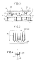
- a fixed baseplate 5 is supported by four pedestal columns 6. On the lower surface of the fixed baseplate 5, a first tilting motor 7 is provided. An output shaft of the first tilting motor 7 is projected upward, and a first driving gear 8 is engaged with the projected end.
- a first driven gear 9 is rotatably mounted on the fixed baseplate 5. The first driven gear 9 is engaged with the driving gear 8 via a first speed reducing idle gear 10.
- a nut is formed at the center of the first driven gear 9, and a first tilting rod 11 is screwed through the first driven gear. Its upper end is projected and is formed in a spherical shape.
- An L-shaped locking member 12 is fixed on the first tilting rod 11. The locking member 12 is slidably penetrating a bottom portion of a housing 30 of the main unit 2. The locking member 12 can be moved freely up and down, while the locking member 12 is restricted from rotating.
- a slide guide 23 is provided on the lower surface of the housing 30, and the upper end of the second tilting rod 17 is slidably touched to the slide guide 23.
- a spring 24 is stretched between the fixed baseplate 5 and the housing 30, and the spring resiliently pushes the lower surface of the housing 30 in a downward direction, i.e. the spring pushes the V-block 21 toward the upper end of the first tilting rod 11.
- the spring also pushes the slide guide 23 toward the upper end of the second tilting rod 17.
- the first tilting motor 7 When the first tilting motor 7 is driven, the first tilting rod 11 is moved in an upward or downward direction, and the housing 30 is tilted with the support pillar 19 at the center.
- the second tilting motor 13 When the second tilting motor 13 is driven, the second tilting rod 17 is moved in an upward or downward direction, and the housing 30 is tilted with the support pillar 19 at the center.
- the forward end of the first tilting rod 11 is engaged with the V-groove 22, and the housing 30 is prevented from rotating in a horizontal direction, and it can be tilted accurately in the two directions by the driving of the second tilting motor 13 and the first tilting motor 7.
- the main unit 2 comprises at least a differential type tilt detection device 33, an arithmetic processing unit 55 and a display unit 140.
- a first light source 35 e.g. an LED, for emitting a light beam in a horizontal direction.
- a first condenser lens 36, a first pattern 37, a second condenser lens 38, and a first half-mirror 39 are arranged on an optical axis of the light beam projected from the first light source 35.
- a liquid member 41 is provided on an optical axis of the light beam reflected from the first half-mirror 39, and the liquid member 41 is placed in a container (not shown) so that it forms a free liquid surface.
- a type of liquid having adequate viscosity e.g. silicone oil, is used.
- the first light source 35 and the liquid member 41 can be arranged at a position conjugate to the free liquid surface.
- a second light source 46 which has a projection light optical axis in parallel to the transmission light optical axis 45 of the first half-mirror 39.
- a fourth condenser lens 47, a second pattern 48, a fifth condenser lens 49, and a third half-mirror 51 are arranged on the projection light optical axis of the second light source 46, and the third half-mirror 51 is at a position facing toward the second half-mirror 42.
- a reflection opening 52 is formed at a position facing toward the third half-mirror 51 on upper part of the housing 30, and a reflection member 53 (to be described later) is placed adjacent to the reflection opening 52.
- the second light source 46, the fourth condenser lens 47, the second pattern 48, the fifth condenser lens 49, and the third half-mirror 51, etc. make up together a fixed reflection member light projection system 50.
- the first half-mirror 39, the second half-mirror 42, the third half-mirror 51, the third condenser lens 43, and the photodetection means 44, etc. make up together a photodetection optical system 56.
- a photodetection signal from the photodetection means 44 is inputted to the arithmetic processing unit 55.
- the arithmetic processing unit 55 tilting of the free liquid surface of the liquid member 41 or tilting of the reflection member 53 is calculated.
- the first tilting motor 7 and the second tilting motor 13 are driven and controlled, and the tilting of the main unit 2 is adjusted.
- the calculation result of the arithmetic processing unit 55 i.e. result of tilting detection by the tilt detecting device 33, is displayed on the display unit 140.
- the data to be displayed are: angular deviation of the free liquid surface of the liquid member 41 from the reflection member 53, alarm display when the angular deviation exceeds an allowable value or a preset value, a tilt angle of the entire laser sighting device, etc.
- the darkfield pattern 80 is a row of slits formed by perforating slits 81 with a predetermined equal spacing (pitch p) between them. It is supposed now that a direction of the row of slits is X-axis direction, for instance.
- Each of the slits 81 is formed in an oblong triangular shape with its width gradually reduced in one direction, and its longitudinal direction is aligned with Y-axis direction.
- a CCD linear sensor 44 may be used, for instance, and the direction of the linear sensor 44 is aligned with X-axis.
- the linear sensor 44 is positioned in a direction perpendicular to the row of images of a plurality of slits 81, 81, Vietnamese (i.e. in X-axis direction).
- the tilt angle in Y-axis direction is calculated from the triangular slit 81 with its width gradually changing.
- the tilting in Y-axis direction can be calculated.
- the tilting of the tilt detecting device 33 i.e. the tilting of the main unit 2 can be detected from the equation (1).
- the darkfield pattern 83 serves as a horizontal reference position when the distance dx is measured.
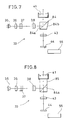
- the light beam emitted from the first light source 35 is turned to a linearly polarized S-polarized light by the first polarizing plate 87 and enters the first half-mirror 39.
- the first half-mirror 39 serves as a polarization beam splitter, which reflects the S-polarized light and transmits the P-polarized light. Therefore, the light beam from the first light source 35 is reflected toward the liquid member 41.
- the light beam reflected by the liquid member 41 passes through the first ⁇ /4 polarization member 88 twice, and the light beam is turned to a linearly polarized S-polarized light. Therefore, the light beam passes through the first half-mirror 39 and the second half-mirror 42 and is received by the photodetection means 44.
- reflection and transmission are performed using the polarized light. This contributes to the improvement of efficiency and to the increase of the receiving light amount at the photodetection means 44. As a result, measurement accuracy is improved.
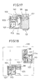
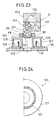
- Fig. 18 shows a fifth variation of the laser beam irradiation unit 3.
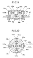
- the fan-shaped laser beams being rotated and moved, cross on the optical axis, which cross perpendicularly to the reflection member, and a vertical point can be formed.
- it can provide the function as the vertical device.
- the photodetection unit 125 is mounted on the upper surface of the housing 30.
- the photodetection unit 125 is designed in form of a doughnut as a whole, and a hollow portion at the center serves as an optical path of the laser beam from the second light source 46.
- the laser beam irradiation unit 3 is mounted on the upper surface of the photodetection unit 125 via the base 93.
- the laser beam irradiation unit 3 is the same as explained in Fig. 14, and detailed description on the laser beam irradiation unit 3 is not given here.
- the above structure is suitable to perform coarse leveling and fine leveling respectively, and the time required for leveling can be reduced. Further, only fine leveling may be performed in case the rotating part of the laser beam irradiation unit 3 is rotated, and this prevents unnecessary vibration or movement of the tilt detecting device 33, i.e. the liquid member 41.
- Stable leveling operation can be ensured during the process such as the change of the projecting the direction of the laser beam.
Landscapes
- Physics & Mathematics (AREA)
- General Physics & Mathematics (AREA)
- Engineering & Computer Science (AREA)
- Radar, Positioning & Navigation (AREA)
- Remote Sensing (AREA)
- Optics & Photonics (AREA)
- Length Measuring Devices By Optical Means (AREA)
- Mounting And Adjusting Of Optical Elements (AREA)
- Optical Radar Systems And Details Thereof (AREA)
Applications Claiming Priority (2)
| Application Number | Priority Date | Filing Date | Title |
|---|---|---|---|
| JP2001094002 | 2001-03-28 | ||
| JP2001094002A JP4712212B2 (ja) | 2001-03-28 | 2001-03-28 | レーザ照準装置 |
Publications (3)
| Publication Number | Publication Date |
|---|---|
| EP1245926A2 true EP1245926A2 (de) | 2002-10-02 |
| EP1245926A3 EP1245926A3 (de) | 2002-11-20 |
| EP1245926B1 EP1245926B1 (de) | 2010-10-27 |
Family
ID=18948269
Family Applications (1)
| Application Number | Title | Priority Date | Filing Date |
|---|---|---|---|
| EP02252287A Expired - Lifetime EP1245926B1 (de) | 2001-03-28 | 2002-03-28 | Laserzielvorrichtung mit Neigungsmessvorrichtung |
Country Status (4)
| Country | Link |
|---|---|
| US (1) | US6675489B2 (de) |
| EP (1) | EP1245926B1 (de) |
| JP (1) | JP4712212B2 (de) |
| DE (1) | DE60238093D1 (de) |
Cited By (6)
| Publication number | Priority date | Publication date | Assignee | Title |
|---|---|---|---|---|
| EP1380812A1 (de) * | 2002-07-10 | 2004-01-14 | Kabushiki Kaisha Topcon | Laserbestrahlungsvorrichtung |
| EP1473540A1 (de) * | 2003-04-29 | 2004-11-03 | Prüftechnik Dieter Busch Ag | Verfahren zur Bestimmung des Niveaus mehrerer Messpunkte sowie Anordnung dafür |
| WO2006074929A1 (en) * | 2005-01-12 | 2006-07-20 | Trimble Jena Gmbh | Inclination detection methods and apparatus |
| EP1691167A3 (de) * | 2005-02-07 | 2006-09-13 | Martin R. Hamar | Laserausrichtungsgerät |
| EP1790940A3 (de) * | 2005-11-08 | 2011-08-10 | Kabushiki Kaisha TOPCON | Lasermessinstrument |
| CN109991999A (zh) * | 2019-03-29 | 2019-07-09 | 郑州信大捷安信息技术股份有限公司 | 无人机编队自定位系统及方法 |
Families Citing this family (34)
| Publication number | Priority date | Publication date | Assignee | Title |
|---|---|---|---|---|
| JP4317639B2 (ja) * | 2000-03-29 | 2009-08-19 | 株式会社トプコン | レーザ測量機 |
| JP4614565B2 (ja) * | 2001-03-28 | 2011-01-19 | 株式会社トプコン | レーザ光線照射装置 |
| US6892464B2 (en) * | 2002-03-13 | 2005-05-17 | Kabushiki Kaisha Topcon | Laser sighting device |
| DE10325859B3 (de) * | 2003-06-06 | 2004-06-03 | Hilti Ag | Rotationsbaulaser |
| JP4267971B2 (ja) * | 2003-06-13 | 2009-05-27 | 株式会社トプコン | レーザ光線照準装置及び光軸補償方法 |
| DE10335207A1 (de) * | 2003-07-03 | 2005-02-03 | Optris Gmbh | Visiereinrichtung und Vorrichtung mit einer kontaktlos oder kontaktbehaftet einsetzbaren Mess-, Arbeits- und/oder Wirkeinrichtung |
| JP4282432B2 (ja) | 2003-10-14 | 2009-06-24 | 株式会社トプコン | 回転レーザ装置の受光装置 |
| US7096591B2 (en) * | 2004-04-08 | 2006-08-29 | Trimble Navigation Limited | Dual axis single motor platform adjustments system |
| TWI258569B (en) * | 2004-05-12 | 2006-07-21 | Asia Optical Co Inc | Spectroscope device for side by side laser level |
| DE102004053249B4 (de) * | 2004-11-04 | 2006-08-17 | Hilti Ag | Baulaser mit neigbarem Umlenkmittel |
| DE102005000048A1 (de) * | 2005-04-29 | 2006-11-02 | Hilti Ag | Neigbarer Baulaser |
| US7497019B2 (en) | 2005-08-04 | 2009-03-03 | Irwin Industrial Tool Company | Laser reference device |
| US7328516B2 (en) * | 2005-08-05 | 2008-02-12 | Irwin Industrial Tool Company | Laser level |
| US7392592B2 (en) | 2005-10-07 | 2008-07-01 | Milwaukee Electric Tool Corporation | Ruggedized laser level |
| JP4197530B2 (ja) * | 2006-11-01 | 2008-12-17 | 株式会社オーディオテクニカ | レーザー墨出し器 |
| US7861424B2 (en) * | 2006-11-13 | 2011-01-04 | Robert Bosch Tool Corporation | Pipe laser |
| DE102009042123B3 (de) * | 2009-09-18 | 2011-02-10 | Trimble Jena Gmbh | Geodätisches Instrument und Verfahren hierzu |
| EP2496911B1 (de) | 2009-11-02 | 2016-04-20 | Infinity Laser Measuring LLC | Lasermessung eines fahrzeugrahmens |
| JP5560054B2 (ja) * | 2010-01-22 | 2014-07-23 | 株式会社トプコン | 傾斜検出装置及びレーザ測量機 |
| CN102445187B (zh) * | 2010-10-12 | 2013-11-13 | 上海微电子装备有限公司 | 一种水平测量装置 |
| FR2966236A1 (fr) * | 2010-10-13 | 2012-04-20 | Psp Outil | Niveau laser comprenant un mode pente numerique. |
| FR2966238A1 (fr) * | 2010-10-13 | 2012-04-20 | Psp Outil | Niveau laser comprenant un module de detection de mouvement. |
| US8549764B2 (en) * | 2011-09-23 | 2013-10-08 | Lexmark International, Inc. | Fluid tilt sensor within ink tank supply item for micro-fluid applications |
| JP6055179B2 (ja) * | 2011-12-19 | 2016-12-27 | 株式会社トプコン | 回転角検出装置及び測量装置 |
| US9571794B2 (en) | 2011-12-19 | 2017-02-14 | Kabushiki Kaisha Topcon | Surveying apparatus |
| US20140111813A1 (en) * | 2012-10-19 | 2014-04-24 | Hamar Laser Instruments, Inc. | Optical assembly and laser alignment apparatus |
| JP6227324B2 (ja) * | 2013-08-23 | 2017-11-08 | 株式会社トプコン | 測量機及び測量作業システム |
| JP6209021B2 (ja) * | 2013-08-23 | 2017-10-04 | 株式会社トプコン | 測量機 |
| US9303990B2 (en) | 2014-04-11 | 2016-04-05 | Black & Decker Inc. | Laser line generating device |
| JP6324270B2 (ja) * | 2014-08-28 | 2018-05-16 | 株式会社トプコン | 測定装置および傾斜センサ装置 |
| JP6752525B2 (ja) | 2016-11-15 | 2020-09-09 | 株式会社トプコン | 傾斜センサ |
| CN108871278B (zh) * | 2018-08-19 | 2023-07-25 | 天津大学 | 一种液体表面反射式双轴光电水平仪及方法 |
| JP6719017B1 (ja) * | 2019-09-27 | 2020-07-08 | 小林製薬株式会社 | 繊維製品用洗浄剤組成物 |
| CN114964153B (zh) * | 2022-06-16 | 2024-04-12 | 广东工业大学 | 一种基于激光定位的地基沉降监测装置及其测量方法 |
Family Cites Families (24)
| Publication number | Priority date | Publication date | Assignee | Title |
|---|---|---|---|---|
| US2460836A (en) * | 1946-06-04 | 1949-02-08 | American Instr Co Inc | Level device employing a light reflecting liquid surface as a horizontal refrence surface |
| US3905707A (en) * | 1972-05-01 | 1975-09-16 | Wieland Feist | Optical level |
| JPS5899712A (ja) * | 1981-12-09 | 1983-06-14 | Tokyo Optical Co Ltd | 傾斜角測定装置 |
| US4710635A (en) * | 1986-04-14 | 1987-12-01 | Becton, Dickinson And Company | Dual laser excitation from single laser source |
| JPH0328409A (ja) * | 1989-06-27 | 1991-02-06 | Taiyo Kogyo Kk | フロートフェンス |
| JPH0734336Y2 (ja) * | 1989-07-28 | 1995-08-02 | 株式会社ソキア | 照射光学装置を搭載した測量機 |
| JP2913984B2 (ja) * | 1992-03-11 | 1999-06-28 | 株式会社ニコン | 傾斜角測定装置 |
| JP2917261B2 (ja) * | 1992-03-19 | 1999-07-12 | 株式会社トプコン | レーザ測量機 |
| US5636018A (en) * | 1992-07-09 | 1997-06-03 | Kabushiki Kaisha Topcon | Laser beam survey instrument having a tiltable laser beam axis and tilt detectors |
| JPH0697042A (ja) * | 1992-09-17 | 1994-04-08 | Hitachi Ltd | ビーム分割装置 |
| JP3519777B2 (ja) * | 1994-04-08 | 2004-04-19 | 株式会社トプコン | 角度自動補償装置 |
| JPH08184438A (ja) * | 1994-12-28 | 1996-07-16 | Laser Techno Kk | 墨出し用レーザー装置 |
| CH691931A5 (de) * | 1995-12-21 | 2001-11-30 | Ammann Holding Ag | Laserstrahl-Nivelliergerät sowie Verfahren zum Betrieb eines Laserstrahl-Nivelliergerätes und dazugehöriges Hilfsmittel. |
| US5838431A (en) * | 1996-01-16 | 1998-11-17 | Asahi Kogaku Kogyo Kabushiki Kaisha | Laser marking device |
| JPH09229685A (ja) * | 1996-02-21 | 1997-09-05 | Alps Electric Co Ltd | レーザ墨出し表示器 |
| CH692254A5 (de) * | 1996-06-29 | 2002-04-15 | Zeiss Carl | Mikroskop mit einer Autofokus-Anordnung. |
| JPH10213435A (ja) * | 1997-01-29 | 1998-08-11 | Nikon Corp | 基準光発生装置 |
| TW323787U (en) * | 1997-07-10 | 1997-12-21 | qi-ying Wu | Three-axis automatic point and line projecting and displaying device |
| JP3794599B2 (ja) | 1997-07-31 | 2006-07-05 | 株式会社トプコン | 光軸補償装置 |
| JP3787736B2 (ja) * | 1997-10-08 | 2006-06-21 | 株式会社トプコン | 傾斜センサ |
| JP4216386B2 (ja) * | 1998-12-29 | 2009-01-28 | 株式会社トプコン | 回転レーザ装置 |
| US6399940B1 (en) * | 1999-05-10 | 2002-06-04 | Fanuc America Corporation | Optical rotary position encoder |
| JP2001074450A (ja) * | 1999-09-01 | 2001-03-23 | Sony Corp | デジタル水準器及び水準器付き三脚 |
| JP4653898B2 (ja) * | 2001-03-28 | 2011-03-16 | 株式会社トプコン | 傾斜検出装置 |
-
2001
- 2001-03-28 JP JP2001094002A patent/JP4712212B2/ja not_active Expired - Fee Related
-
2002
- 2002-03-13 US US10/097,917 patent/US6675489B2/en not_active Expired - Fee Related
- 2002-03-28 DE DE60238093T patent/DE60238093D1/de not_active Expired - Lifetime
- 2002-03-28 EP EP02252287A patent/EP1245926B1/de not_active Expired - Lifetime
Cited By (12)
| Publication number | Priority date | Publication date | Assignee | Title |
|---|---|---|---|---|
| EP1380812A1 (de) * | 2002-07-10 | 2004-01-14 | Kabushiki Kaisha Topcon | Laserbestrahlungsvorrichtung |
| EP1473540A1 (de) * | 2003-04-29 | 2004-11-03 | Prüftechnik Dieter Busch Ag | Verfahren zur Bestimmung des Niveaus mehrerer Messpunkte sowie Anordnung dafür |
| US7212294B2 (en) | 2003-04-29 | 2007-05-01 | Prüftechnik Dieter Busch AG | Method for determination of the level of two or more measurement points, and an arrangement for this purpose |
| WO2006074929A1 (en) * | 2005-01-12 | 2006-07-20 | Trimble Jena Gmbh | Inclination detection methods and apparatus |
| US7388658B2 (en) | 2005-01-12 | 2008-06-17 | Trimble Jena Gmbh | Inclination detection methods and apparatus |
| US7688433B2 (en) | 2005-01-12 | 2010-03-30 | Trimble Jena Gmbh | Inclination detection methods and apparatus |
| US7973916B2 (en) | 2005-01-12 | 2011-07-05 | Trimble Navigation Limited | Inclination detection methods and apparatus |
| EP1691167A3 (de) * | 2005-02-07 | 2006-09-13 | Martin R. Hamar | Laserausrichtungsgerät |
| US7708204B2 (en) | 2005-02-07 | 2010-05-04 | Hamar Laser Instruments, Inc. | Laser alignment apparatus |
| EP1790940A3 (de) * | 2005-11-08 | 2011-08-10 | Kabushiki Kaisha TOPCON | Lasermessinstrument |
| CN109991999A (zh) * | 2019-03-29 | 2019-07-09 | 郑州信大捷安信息技术股份有限公司 | 无人机编队自定位系统及方法 |
| CN109991999B (zh) * | 2019-03-29 | 2021-10-29 | 郑州信大捷安信息技术股份有限公司 | 无人机编队自定位系统及方法 |
Also Published As
| Publication number | Publication date |
|---|---|
| EP1245926A3 (de) | 2002-11-20 |
| US6675489B2 (en) | 2004-01-13 |
| DE60238093D1 (de) | 2010-12-09 |
| EP1245926B1 (de) | 2010-10-27 |
| JP4712212B2 (ja) | 2011-06-29 |
| JP2002286450A (ja) | 2002-10-03 |
| US20020138997A1 (en) | 2002-10-03 |
Similar Documents
| Publication | Publication Date | Title |
|---|---|---|
| EP1245926B1 (de) | Laserzielvorrichtung mit Neigungsmessvorrichtung | |
| US6892464B2 (en) | Laser sighting device | |
| US5894123A (en) | Laser rotary irradiating system for irradiating a laser beam | |
| JP3582918B2 (ja) | レーザ測量機 | |
| US5629756A (en) | Laser beam projection apparatus | |
| US5287365A (en) | Compact laser apparatus | |
| US7130035B2 (en) | Target for surveying instrument | |
| JPH09210687A (ja) | レーザレベル装置 | |
| EP1321739B1 (de) | Positionsmesseinrichtung | |
| CN113030921B (zh) | 多线激光雷达光机调校装置及转镜模组的检测方法 | |
| US6067152A (en) | Alignment range for multidirectional construction laser | |
| US6931737B1 (en) | Laser level device | |
| US9952040B2 (en) | Tilt detecting device and rotary laser apparatus | |
| EP4239286B1 (de) | Vermessungsinstrument | |
| US6782015B1 (en) | Laser survey instrument | |
| EP1524496A1 (de) | Neigungsmessvorrichtung | |
| US6088623A (en) | System and method for leveling an apparatus | |
| US7092076B2 (en) | Surveying instrument | |
| EP1245925B1 (de) | Neigungsmessvorrichtung | |
| EP1524495A1 (de) | Laserbeleuchtungssystem | |
| EP1041361A2 (de) | Nachführ-System für ein automatisches Vermessungsinstrument | |
| JPH09229685A (ja) | レーザ墨出し表示器 | |
| JP4267971B2 (ja) | レーザ光線照準装置及び光軸補償方法 | |
| JPH10318745A (ja) | 水準センサおよびレーザ墨出し表示器 | |
| JPH10176924A (ja) | 水準センサおよびレーザ墨出し表示器 |
Legal Events
| Date | Code | Title | Description |
|---|---|---|---|
| PUAI | Public reference made under article 153(3) epc to a published international application that has entered the european phase |
Free format text: ORIGINAL CODE: 0009012 |
|
| AK | Designated contracting states |
Kind code of ref document: A2 Designated state(s): AT BE CH CY DE DK ES FI FR GB GR IE IT LI LU MC NL PT SE TR |
|
| AX | Request for extension of the european patent |
Free format text: AL;LT;LV;MK;RO;SI |
|
| PUAL | Search report despatched |
Free format text: ORIGINAL CODE: 0009013 |
|
| AK | Designated contracting states |
Kind code of ref document: A3 Designated state(s): AT BE CH CY DE DK ES FI FR GB GR IE IT LI LU MC NL PT SE TR |
|
| AX | Request for extension of the european patent |
Free format text: AL;LT;LV;MK;RO;SI |
|
| RIC1 | Information provided on ipc code assigned before grant |
Free format text: 7G 01C 9/20 A, 7G 01C 9/06 B, 7G 01C 15/00 B, 7G 02B 27/64 B, 7G 01C 5/02 B |
|
| 17P | Request for examination filed |
Effective date: 20030423 |
|
| AKX | Designation fees paid |
Designated state(s): CH DE LI |
|
| RBV | Designated contracting states (corrected) |
Designated state(s): CH DE LI SE |
|
| RBV | Designated contracting states (corrected) |
Designated state(s): CH DE LI SE |
|
| 17Q | First examination report despatched |
Effective date: 20061222 |
|
| GRAP | Despatch of communication of intention to grant a patent |
Free format text: ORIGINAL CODE: EPIDOSNIGR1 |
|
| GRAS | Grant fee paid |
Free format text: ORIGINAL CODE: EPIDOSNIGR3 |
|
| GRAA | (expected) grant |
Free format text: ORIGINAL CODE: 0009210 |
|
| AK | Designated contracting states |
Kind code of ref document: B1 Designated state(s): CH DE LI SE |
|
| REG | Reference to a national code |
Ref country code: CH Ref legal event code: NV Representative=s name: KIRKER & CIE S.A. Ref country code: CH Ref legal event code: EP |
|
| REF | Corresponds to: |
Ref document number: 60238093 Country of ref document: DE Date of ref document: 20101209 Kind code of ref document: P |
|
| REG | Reference to a national code |
Ref country code: SE Ref legal event code: TRGR |
|
| PLBE | No opposition filed within time limit |
Free format text: ORIGINAL CODE: 0009261 |
|
| STAA | Information on the status of an ep patent application or granted ep patent |
Free format text: STATUS: NO OPPOSITION FILED WITHIN TIME LIMIT |
|
| 26N | No opposition filed |
Effective date: 20110728 |
|
| REG | Reference to a national code |
Ref country code: DE Ref legal event code: R097 Ref document number: 60238093 Country of ref document: DE Effective date: 20110728 |
|
| PGFP | Annual fee paid to national office [announced via postgrant information from national office to epo] |
Ref country code: CH Payment date: 20160311 Year of fee payment: 15 Ref country code: DE Payment date: 20160322 Year of fee payment: 15 |
|
| PGFP | Annual fee paid to national office [announced via postgrant information from national office to epo] |
Ref country code: SE Payment date: 20160311 Year of fee payment: 15 |
|
| REG | Reference to a national code |
Ref country code: DE Ref legal event code: R119 Ref document number: 60238093 Country of ref document: DE |
|
| REG | Reference to a national code |
Ref country code: SE Ref legal event code: EUG Ref country code: CH Ref legal event code: PL |
|
| PG25 | Lapsed in a contracting state [announced via postgrant information from national office to epo] |
Ref country code: SE Free format text: LAPSE BECAUSE OF NON-PAYMENT OF DUE FEES Effective date: 20170329 |
|
| PG25 | Lapsed in a contracting state [announced via postgrant information from national office to epo] |
Ref country code: DE Free format text: LAPSE BECAUSE OF NON-PAYMENT OF DUE FEES Effective date: 20171003 |
|
| PG25 | Lapsed in a contracting state [announced via postgrant information from national office to epo] |
Ref country code: LI Free format text: LAPSE BECAUSE OF NON-PAYMENT OF DUE FEES Effective date: 20170331 Ref country code: CH Free format text: LAPSE BECAUSE OF NON-PAYMENT OF DUE FEES Effective date: 20170331 |