EP1248348A1 - Machine électrique tournante à aimants permanents ainsi que système de géneration de puissance et système d'entraínement utilisant une telle machine - Google Patents
Machine électrique tournante à aimants permanents ainsi que système de géneration de puissance et système d'entraínement utilisant une telle machine Download PDFInfo
- Publication number
- EP1248348A1 EP1248348A1 EP20020007311 EP02007311A EP1248348A1 EP 1248348 A1 EP1248348 A1 EP 1248348A1 EP 20020007311 EP20020007311 EP 20020007311 EP 02007311 A EP02007311 A EP 02007311A EP 1248348 A1 EP1248348 A1 EP 1248348A1
- Authority
- EP
- European Patent Office
- Prior art keywords
- permanent magnet
- rotating electrical
- electrical machine
- type rotating
- magnet type
- Prior art date
- Legal status (The legal status is an assumption and is not a legal conclusion. Google has not performed a legal analysis and makes no representation as to the accuracy of the status listed.)
- Withdrawn
Links
Images


Classifications
-
- H—ELECTRICITY
- H02—GENERATION; CONVERSION OR DISTRIBUTION OF ELECTRIC POWER
- H02K—DYNAMO-ELECTRIC MACHINES
- H02K1/00—Details of the magnetic circuit
- H02K1/06—Details of the magnetic circuit characterised by the shape, form or construction
- H02K1/22—Rotating parts of the magnetic circuit
- H02K1/27—Rotor cores with permanent magnets
- H02K1/2706—Inner rotors
- H02K1/272—Inner rotors the magnetisation axis of the magnets being perpendicular to the rotor axis
- H02K1/274—Inner rotors the magnetisation axis of the magnets being perpendicular to the rotor axis the rotor consisting of two or more circumferentially positioned magnets
- H02K1/2753—Inner rotors the magnetisation axis of the magnets being perpendicular to the rotor axis the rotor consisting of two or more circumferentially positioned magnets the rotor consisting of magnets or groups of magnets arranged with alternating polarity
- H02K1/276—Magnets embedded in the magnetic core, e.g. interior permanent magnets [IPM]
-
- H—ELECTRICITY
- H02—GENERATION; CONVERSION OR DISTRIBUTION OF ELECTRIC POWER
- H02K—DYNAMO-ELECTRIC MACHINES
- H02K29/00—Motors or generators having non-mechanical commutating devices, e.g. discharge tubes or semiconductor devices
- H02K29/03—Motors or generators having non-mechanical commutating devices, e.g. discharge tubes or semiconductor devices with a magnetic circuit specially adapted for avoiding torque ripples or self-starting problems
-
- H—ELECTRICITY
- H02—GENERATION; CONVERSION OR DISTRIBUTION OF ELECTRIC POWER
- H02K—DYNAMO-ELECTRIC MACHINES
- H02K3/00—Details of windings
- H02K3/04—Windings characterised by the conductor shape, form or construction, e.g. with bar conductors
- H02K3/28—Layout of windings or of connections between windings
Definitions
- the present invention relates to the improvement of a permanent magnet type rotating electrical machine and the system using it.
- JP A 06-189481 discloses that multiple slits are formed on the outer periphery of the magnet storage hole to improve punching work of a thin steel plate constituting the armature core and to reduce the circumferential leakage of magnetic flux.
- the Japanese Patent Laid-Open Application No. Hei 11-252840 discloses that slots are installed between the outer periphery of the rotor and the embedded magnet in order to create magnetic resistance, thereby preventing magnetic flux on the horizontal axis.
- these disclosures do not include any description of wiring on the stator side.
- a permanent magnet type rotating electrical machine with stator winding formed on the stator in distributed winding method is disclosed in the Japanese Patent Laid-Open Application No. Hei 05-103453 (JP A 05-103453).
- JP A 05-103453 Japanese Patent Laid-Open Application No. Hei 05-103453
- holes are formed at positions corresponding to 60 and 120 degrees in terms of electric angle of the salient pole to remove the cogging torque of the permanent magnet type rotating electrical machine.
- Hei 09-163647 JP A 09-163647
- Hei 10-178751 JP A 10-178751
- Hei 10-285845 JP A 10-285845
- Hei 10-285851 JP A 10-285851
- An object of the present invention is to provide a permanent magnet type rotating electrical machine and a system using such a machine characterized by reduced vibration and noise and improved efficiency.
- a big vibration noise may occur to the rotating electrical machine and characteristics are deteriorated. And such problems as heat generation, reduced efficiency and deteriorated characteristics may occur to a power generation system. These problems are considered to be caused by an excessive waveform distortion rate of the induced voltage in the permanent magnet type rotating electrical machine. As a result, harmonic wave current flows to the rotating electrical machine so that pulsation torque, vibration and noise are increased or efficiency and characteristic is deteriorated.
- Such an arrangement of flux barriers causes local magnetic saturation on the bridge of the magnetic pole, and the magnetic path is divided into three portions; one big magnetic path at the center and two smaller ones on both sides.
- the waveform of the surface magnetic flux density of the rotor is brought closer to the sinusoidal waveform, thereby reducing the distortion of induced voltage waveform.
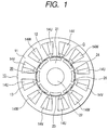
- Fig. 1 is a cross sectional view at a right angle to the shaft representing a 3-phase, 8-pole, 12-slot permanent magnet type rotating electrical machine as one embodiment of the present invention.
- stator 10 is configured by concentrated winding of the U-phase stator wiring 14U, V-phase stator wiring 14V and W-phase stator wiring 14W on the stator teeth 12 in twelve slots 13 formed in the almost annular stator core 11.
- a rotor 20 is formed by fitting the rotor core 21 into rotary shaft 22 and locking it therein and by inserting and assembling eight arc-shaped permanent magnets 24 into the punched permanent magnet insertion holes 23 formed in the rotor core 21 in such a way that the N and S poles will be located alternately in the axial direction.
- the rotor 20 is installed rotatably inside the stator 10 so that it has a gap G with the tip of the stator teeth 12. Grooves 26 are formed on the bridge 25 on the outer periphery of the permanent magnet insertion hole 23 as flux barriers.
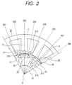
- Fig. 2 is an enlarged view representing the relationship between stator tooth 12 and rotor 20 in Fig. 1.
- Extension lines 201 to 208 extending from the center point X of the rotary shaft 22 denote electric angles of 0, 45, 90, 135, 180, 225, 270 and 315 degrees, respectively.
- Arrow marks 210 to 214 designate magnetic paths.
- Grooves 26 formed on the permanent magnet 24 side of the bridge 25 are provided at electric angles of 45, 135, 225 and 315 degrees at an equally spaced interval.
- a permanent magnet type rotating electrical machine comprising a stator 10 with concentrated winding provided on the tooth of the stator core 11 and a rotor 20 with permanent magnets 24 embedded therein
- two grooves 26 extending in the axial direction as flux barriers are formed for each magnetic pole of the rotor 20 on the bridge 25 between the permanent magnet 24 and outer surface of the rotor 20 to ensure that these grooves are located at an equally spaced interval at an electric angle of 90 degrees at a distance of W2 (Fig. 4) over the entire outer periphery of rotor 20.
- the waveform of the magnetic flux density can be brought closer to the sinusoidal waveform if two flux barriers extending in the axial direction are arranged for each magnetic pole of the rotor at the position where the width of the permanent magnet 24 is divided into three parts at the position where the width of the permanent magnet 24 or the magnetic pole is divided into three parts in such a way that the ratio of each of both ends and center is 1 to 2 or more.
- flux barriers are arranged at an equally spaced interval over the entire outer periphery of the rotor, further reduction of cogging torque can be achieved, according to the experiment conducted by the present inventors.
- Fig. 3 shows an induced voltage waveform illustrating the effect of the embodiment of Fig. 1.
- the horizontal axis (of a graph) indicates the rotor position (shown in terns of mechanical angle), and the vertical axis represents the induced voltage value. It shows the induced voltage waveform 31 in the embodiment of Fig. 1 when grooves 26 are formed, and induced voltage waveform 32 without grooves 26.
- the distortion rate R (%) of the induced voltage waveform is represented by the percentage of the total sum of rms 2- to N-degree frequency components with respect to rms fundamental wave frequency components when induced voltage waveform is subjected to expansion into Fourier series, and N-degree frequency component is subjected to f(N).
- the distortion rate R of the induced voltage waveform is calculated using the result of Fig. 3.
- the distortion rate R of the induced voltage waveform 32 is 11.1 percent, whereas distortion rate R of induced voltage waveform 31 according to the present embodiment is 7.62%. This indicates that distortion rate R is decreased to about two thirds by formation of grooves 26 as flux barriers.
- Fig. 4 is an enlarged view of stator teeth 2 and permanent magnet insertion holes 23 as the embodiment in Fig. 1.
- dimensions are determined as follows: Width Wt of tooth 12: 9mm, width W1 of groove 26: 1mm, space W2 between grooves 26: 8mm, width W3 of magnet insertion holes 23 outside the groove 26: 1.2mm, bridge thickness h: 1mm, and height t of groove 26: 0.5mm.
- the maximum value W1max of width W1 of groove 26 that can be adopted is 2mm, and the minimum value W1min of the same is 0.6mm.
- width W2 of the magnetic path at the center is divided by groove 26 and is greater than twice width W3 of the magnetic path on both sides.
- groove height coefficient C1 and groove width coefficient C2 are defined as shown above:
- Fig. 5 is a chart representing the characteristics of waveform distortion rate R with respect to groove height.
- the vertical axis represents the waveform distortion rate R, and horizontal axis indicates the groove height coefficient C1.
- Line 51 shows changes in the distortion rate R of induced voltage waveform when the height t of groove 26 is changed variously.
- Distortion rate R increases with groove height coefficient C1, and the maximum value of 13.3% is reached when groove height coefficient C1 is 0.8. It exhibits a value greater than the distortion rate of the induced voltage waveform 32. This indicates that 0.2 ⁇ C1 ⁇ 0.6 should be preferred. Further, 0.2 ⁇ C1 ⁇ 0.4 allows the distortion rate to be minimized.
- Fig. 6 is a chart representing the characteristic of waveform distortion rate R relative to the groove width as the first embodiment of the present invention.
- the vertical axis indicates waveform distortion rate R
- the horizontal axis represents groove width coefficient C2.
- Line 61 shows changes of the distortion rate R of induced voltage waveform when the width W1 of groove 26 is changed.
- the groove width coefficient C2 is 0.5 ⁇ C2 ⁇ 1.2
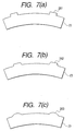
- Fig. 7 represents a variation of groove 26.
- Fig. 7 (a) displays the rectangular groove 261 shown in Figs. 1, 2 and 4
- Fig. 7 (b) shows a trapezoidal groove 262
- Fig. 7 (c) represents a arch-shaped groove 63. They performs almost the same functions as flux barriers.
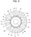
- Fig. 8 is a cross sectional view at right angle to the shaft representing the permanent magnet type rotating electrical machine as a second embodiment of the present invention.
- the same components as those in Fig. 1 will be assigned with the same numerals to avoid redundant explanation.
- the difference from Fig. 1 is that holes 81 extending in the axial direction are formed at electric angles 45 and 135 degrees on the bridge 25 between the permanent magnet insertion hole 23 and rotor surface.
- Fig. 9 represents the induced voltage waveform in the second embodiment given in Fig. 8.
- the vertical axis indicates the induced voltage and the horizontal axis shows the rotor position (given in terms of a mechanical angle).
- It indicates the induced voltage waveform 91 according to the embodiment of Fig. 8 where a hole 81 is formed, and induced voltage waveform 92 (same as 32 of Fig. 3) without hole 81.
- This result is used to calculate the distortion rate R of induced voltage waveform.
- the distortion rate R of the induced voltage waveform 91 is 8.09%, suggesting that distortion rate R of the induced voltage waveform can be reduced by formation of hole 81 on bridge 25.
- Fig. 10 is a cross sectional view at a right angle to the shaft representing the permanent magnet type rotating electrical machine as the third embodiment of the present invention.
- the same components as those in Fig. 8 will be assigned with the same numerals to avoid redundant explanation. It indicates an application to the 3-phase, 8-pole, 12-slot permanent magnet type rotating electrical machine using a linear permanent magnet.
- the difference from Fig. 8 is that eight linear permanent magnets 102 are inserted into the punched permanent magnet insertion holes 23 formed in the rotor core 21 from the axial direction so that N- and S-poles will arranged alternately, and holes 103 are formed as flux barriers on the same bridge as that in Fig. 8.
- Fig. 11 shows the induced voltage waveform in the third embodiment of Fig. 10.
- the vertical axis indicates the induced voltage value, and the horizontal axis denotes the rotor position (shown in terms of mechanical angle).
- It shows the induced voltage waveform 111 in the embodiment of Fig. 10 when grooves 103 are formed, and induced voltage waveform 112 without grooves 103.
- This result is used to calculate the distortion rate R of induced voltage waveform.
- the distortion rate of the induced voltage waveform 111 is 6.53%
- that of the induced voltage waveform 112 is 10.11%.
- formation of the hole 103 allows magnetic saturation partially on the bridge 25, and the surface magnetic flux density distribution of the rotor 20 exhibits sinusoidal waveform, with the result that distortion rate of induced voltage waveform is reduced.
- Fig. 12 is a block diagram representing an approximate configuration of a power generation system using the permanent magnet type rotating electrical machine of the present invention.
- the power generation system 120 is equipped with a generator 123 comprising any one of the permanent magnet type rotating electrical machines shown in the first to third embodiments wherein the permanent magnet type rotating electrical machine is connected to a drive source 121 through a rotary shaft 122. It is composed of an electric power converter 125 connected to the permanent magnet type rotating electrical machine 123 through a 3-phase electric power cable 124, and an output terminal 127 connected to electric power converter 125 through a 3-phase or 1-phase electric power cable 126. Connection between output terminal 127 and electric power system allows electric power to be fed to the electric power system from the power generation system 120. Such an arrangement reduces the distortion rate of the induced voltage waveform, hence, harmonic wave current flowing into the rotating electrical machine 123. Thus, a highly efficient power generation system can be provided because of reduced loss.
- Fig. 13 is a block diagram representing an approximate configuration of a drive system using the permanent magnet type rotating electrical machine of the present invention.
- this system has an electric power converter 133 connected to the power supply 131 through a 1-phase or 3-phase power supply cable 132.
- the system also have a motor 135 comprising any one of the permanent magnet type rotating electrical machines shown in the first to third embodiments, wherein this permanent magnet type rotating electrical machine is connected to this electric power converter 133 through a 3-phase electric power cable 134.
- It shows the drive system 130 capable of driving a rotary load 137 connected to the rotary shaft 136 of the permanent magnet type rotating electrical machine 135. This configuration reduces harmonic wave current flowing into the rotating electrical machine 135, and provides a highly efficient power generation system because of reduced loss.
- the present invention provides a permanent magnet type rotating electrical machine characterized by reduced distortion rate of induced voltage waveform, hence, reduced vibration and noise or by improved efficiency. Further, a highly efficient power generation system or a drive system reduced vibration/noise can be provided by using this machine.
Landscapes
- Engineering & Computer Science (AREA)
- Power Engineering (AREA)
- Iron Core Of Rotating Electric Machines (AREA)
- Permanent Field Magnets Of Synchronous Machinery (AREA)
- Permanent Magnet Type Synchronous Machine (AREA)
- Motor Or Generator Frames (AREA)
Applications Claiming Priority (2)
| Application Number | Priority Date | Filing Date | Title |
|---|---|---|---|
| JP2001106972 | 2001-04-05 | ||
| JP2001106972A JP3748387B2 (ja) | 2001-04-05 | 2001-04-05 | 永久磁石式回転電機及びそれを用いた発電システムと駆動システム |
Publications (1)
| Publication Number | Publication Date |
|---|---|
| EP1248348A1 true EP1248348A1 (fr) | 2002-10-09 |
Family
ID=18959382
Family Applications (1)
| Application Number | Title | Priority Date | Filing Date |
|---|---|---|---|
| EP20020007311 Withdrawn EP1248348A1 (fr) | 2001-04-05 | 2002-04-03 | Machine électrique tournante à aimants permanents ainsi que système de géneration de puissance et système d'entraínement utilisant une telle machine |
Country Status (4)
| Country | Link |
|---|---|
| US (1) | US6657350B2 (fr) |
| EP (1) | EP1248348A1 (fr) |
| JP (1) | JP3748387B2 (fr) |
| CN (1) | CN1379528A (fr) |
Cited By (1)
| Publication number | Priority date | Publication date | Assignee | Title |
|---|---|---|---|---|
| EP2296253A3 (fr) * | 2009-09-15 | 2016-02-24 | Robert Bosch GmbH | Moteur électrique à excitation par aimants permanents avec couple de charge réduit |
Families Citing this family (36)
| Publication number | Priority date | Publication date | Assignee | Title |
|---|---|---|---|---|
| US7272594B1 (en) | 2001-05-31 | 2007-09-18 | Autonomy Corporation Ltd. | Method and apparatus to link to a related document |
| EP1542336A1 (fr) * | 2002-08-21 | 2005-06-15 | Toyota Jidosha Kabushiki Kaisha | Moteur de vehicule |
| EP1450470B1 (fr) * | 2003-02-21 | 2012-09-19 | Rexroth Indramat GmbH | Machine synchrone à aimants permanents internes |
| JP4311182B2 (ja) * | 2003-12-08 | 2009-08-12 | 日産自動車株式会社 | 回転電機の回転子 |
| GB2411014A (en) * | 2004-02-11 | 2005-08-17 | Autonomy Corp Ltd | Automatic searching for relevant information |
| US7772735B2 (en) * | 2006-04-19 | 2010-08-10 | Asmo Co., Ltd. | Embedded magnet type rotating electric machine |
| US7385328B2 (en) | 2006-05-23 | 2008-06-10 | Reliance Electric Technologies, Llc | Cogging reduction in permanent magnet machines |
| JP5259934B2 (ja) * | 2006-07-20 | 2013-08-07 | 株式会社日立産機システム | 永久磁石式回転電機及びそれを用いた圧縮機 |
| US8138651B2 (en) * | 2007-11-30 | 2012-03-20 | GM Global Technology Operations LLC | Methods and apparatus for a permanent magnet machine with an added air barrier |
| TW200926559A (en) * | 2007-12-04 | 2009-06-16 | Ind Tech Res Inst | A rotating electric machine with a permanent magnet type pole core structure to monimizing cogging torque |
| JP5278003B2 (ja) * | 2009-01-30 | 2013-09-04 | トヨタ自動車株式会社 | 電動機 |
| JP2011109734A (ja) * | 2009-11-12 | 2011-06-02 | Ihi Corp | 回転機 |
| US8729763B2 (en) * | 2010-07-23 | 2014-05-20 | Toyota Jidosha Kabushiki Kaisha | Rotor and IPM motor |
| US8390276B2 (en) | 2010-09-27 | 2013-03-05 | Bourns Incorporated | Target magnet assembly for a sensor used with a steering gear |
| US8448528B2 (en) * | 2010-09-27 | 2013-05-28 | Bourns Incorporated | Three-piece torque sensor assembly |
| JP5802487B2 (ja) * | 2011-08-30 | 2015-10-28 | 株式会社東芝 | 永久磁石式回転電機 |
| US20150171680A1 (en) * | 2012-06-14 | 2015-06-18 | Daikin Industries, Ltd. | Interior permanent magnet rotary electric machine |
| WO2014045445A1 (fr) * | 2012-09-24 | 2014-03-27 | 三菱電機株式会社 | Moteur électrique à aimant permanent intégré |
| US9323767B2 (en) | 2012-10-01 | 2016-04-26 | Longsand Limited | Performance and scalability in an intelligent data operating layer system |
| DE102012223598A1 (de) * | 2012-12-18 | 2014-06-18 | Robert Bosch Gmbh | Rotor für eine Elektromaschine mit Aussparungen in Magnettaschen |
| JP5971666B2 (ja) * | 2013-03-14 | 2016-08-17 | 三菱電機株式会社 | 永久磁石埋込型電動機及び圧縮機 |
| WO2014199466A1 (fr) * | 2013-06-12 | 2014-12-18 | 三菱電機株式会社 | Moteur électrique à aimant permanant intégré, et compresseur |
| DE102013019318A1 (de) * | 2013-11-20 | 2015-05-21 | Brose Fahrzeugteile GmbH & Co. Kommanditgesellschaft, Würzburg | Verfahren zur Herstellung eines Rotors |
| KR20150063217A (ko) * | 2013-11-29 | 2015-06-09 | 삼성전자주식회사 | 모터 및 이를 포함하는 세탁기 |
| CN106797146B (zh) * | 2014-08-25 | 2019-03-12 | 三菱电机株式会社 | 电动机、压缩机以及制冷循环装置 |
| JPWO2017085861A1 (ja) * | 2015-11-20 | 2018-03-29 | 三菱電機株式会社 | 回転電機 |
| US10868448B2 (en) * | 2016-01-12 | 2020-12-15 | Hitachi Automotive Systems, Ltd. | Dynamo-electric machine and vehicle |
| US20180205302A1 (en) * | 2017-01-19 | 2018-07-19 | Hamilton Sundstrand Corporation | Permanent magnet (pm) brushless machine with outer rotor |
| FR3067880B1 (fr) * | 2017-06-15 | 2020-07-17 | Moteurs Leroy-Somer | Machine electrique tournante |
| CN107332370A (zh) * | 2017-08-18 | 2017-11-07 | 苏州德迈科电机技术有限公司 | 一种智能装备用高性能永磁同步伺服电机的磁路结构 |
| JP6904882B2 (ja) * | 2017-10-30 | 2021-07-21 | オークマ株式会社 | 同期電動機の回転子 |
| GB2569142B (en) * | 2017-12-06 | 2023-05-03 | Trw Ltd | An interior permanent magnet motor |
| CN112350473B (zh) * | 2019-08-07 | 2025-09-16 | 安徽威灵汽车部件有限公司 | 转子冲片、转子铁芯、转子、电机及车辆 |
| KR102858700B1 (ko) * | 2019-09-03 | 2025-09-12 | 엘지이노텍 주식회사 | 모터 |
| JP2021044857A (ja) * | 2019-09-06 | 2021-03-18 | 日立オートモティブシステムズ株式会社 | 回転電機 |
| WO2026014922A1 (fr) * | 2024-07-09 | 2026-01-15 | 남상욱 | Dispositif de production d'énergie intégré permettant de charger et décharger indépendamment chaque module de batterie d'une pluralité de modules de batterie, et système de production d'énergie intégré pour véhicule électrique à autonomie augmentée le comprenant |
Citations (7)
| Publication number | Priority date | Publication date | Assignee | Title |
|---|---|---|---|---|
| JPH05103453A (ja) * | 1991-10-07 | 1993-04-23 | Toshiba Corp | 突極形ブラシレスdcモータ |
| JPH07336917A (ja) * | 1994-06-07 | 1995-12-22 | Toshiba Corp | 永久磁石形モータ及び冷却装置用コンプレッサ |
| JPH09131009A (ja) * | 1995-10-31 | 1997-05-16 | Mitsubishi Electric Corp | 永久磁石回転子 |
| JPH1146464A (ja) * | 1997-07-25 | 1999-02-16 | Sanyo Electric Co Ltd | 永久磁石モータ |
| JPH11252840A (ja) * | 1998-02-26 | 1999-09-17 | Meidensha Corp | 回転電機の回転子 |
| DE19851883A1 (de) * | 1998-11-10 | 2000-05-18 | Siemens Ag | Permanenterregte Synchronmaschine |
| US6208054B1 (en) * | 1996-10-18 | 2001-03-27 | Hitachi, Ltd. | Permanent magnet electric rotating machine and electromotive vehicle using permanent magnet electric rotating machine |
Family Cites Families (13)
| Publication number | Priority date | Publication date | Assignee | Title |
|---|---|---|---|---|
| US5097166A (en) * | 1990-09-24 | 1992-03-17 | Reuland Electric | Rotor lamination for an AC permanent magnet synchronous motor |
| US5304882A (en) * | 1992-05-11 | 1994-04-19 | Electric Power Research Institute, Inc. | Variable reluctance motors with permanent magnet excitation |
| JPH06189481A (ja) | 1992-11-06 | 1994-07-08 | Aichi Emerson Electric Co Ltd | 回転子 |
| JPH09163647A (ja) | 1995-11-30 | 1997-06-20 | Toshiba Corp | 永久磁石回転子 |
| US5811904A (en) * | 1996-03-21 | 1998-09-22 | Hitachi, Ltd. | Permanent magnet dynamo electric machine |
| JPH09285088A (ja) * | 1996-04-12 | 1997-10-31 | Hitachi Ltd | 永久磁石回転電機及びそれを用いた電動車両 |
| JP3747107B2 (ja) | 1996-12-18 | 2006-02-22 | アイチエレック株式会社 | 電動機 |
| JP3631583B2 (ja) | 1997-03-31 | 2005-03-23 | 三菱電機株式会社 | 永久磁石形モータ |
| JP3739890B2 (ja) | 1997-04-07 | 2006-01-25 | 三菱電機株式会社 | 永久磁石型モータ |
| JPH11103546A (ja) * | 1997-09-29 | 1999-04-13 | Fujitsu General Ltd | 永久磁石電動機 |
| DE69928363T2 (de) * | 1998-12-25 | 2006-06-01 | Matsushita Electric Industrial Co., Ltd., Kadoma | Motor mit im Rotor eingebetteten geteilten Dauermagneten |
| JP2000287395A (ja) * | 1999-03-30 | 2000-10-13 | Toshiba Corp | 永久磁石式リラクタンス型回転電機の回転子 |
| JP2002112476A (ja) * | 2000-09-28 | 2002-04-12 | Hitachi Ltd | 永久磁石式回転電機 |
-
2001
- 2001-04-05 JP JP2001106972A patent/JP3748387B2/ja not_active Expired - Lifetime
- 2001-09-26 US US09/962,124 patent/US6657350B2/en not_active Expired - Lifetime
-
2002
- 2002-04-03 EP EP20020007311 patent/EP1248348A1/fr not_active Withdrawn
- 2002-04-04 CN CN02105442.8A patent/CN1379528A/zh active Pending
Patent Citations (7)
| Publication number | Priority date | Publication date | Assignee | Title |
|---|---|---|---|---|
| JPH05103453A (ja) * | 1991-10-07 | 1993-04-23 | Toshiba Corp | 突極形ブラシレスdcモータ |
| JPH07336917A (ja) * | 1994-06-07 | 1995-12-22 | Toshiba Corp | 永久磁石形モータ及び冷却装置用コンプレッサ |
| JPH09131009A (ja) * | 1995-10-31 | 1997-05-16 | Mitsubishi Electric Corp | 永久磁石回転子 |
| US6208054B1 (en) * | 1996-10-18 | 2001-03-27 | Hitachi, Ltd. | Permanent magnet electric rotating machine and electromotive vehicle using permanent magnet electric rotating machine |
| JPH1146464A (ja) * | 1997-07-25 | 1999-02-16 | Sanyo Electric Co Ltd | 永久磁石モータ |
| JPH11252840A (ja) * | 1998-02-26 | 1999-09-17 | Meidensha Corp | 回転電機の回転子 |
| DE19851883A1 (de) * | 1998-11-10 | 2000-05-18 | Siemens Ag | Permanenterregte Synchronmaschine |
Non-Patent Citations (5)
| Title |
|---|
| PATENT ABSTRACTS OF JAPAN vol. 17, no. 460 (E - 1419) 23 August 1993 (1993-08-23) * |
| PATENT ABSTRACTS OF JAPAN vol. 1996, no. 4 30 April 1996 (1996-04-30) * |
| PATENT ABSTRACTS OF JAPAN vol. 1997, no. 9 30 September 1997 (1997-09-30) * |
| PATENT ABSTRACTS OF JAPAN vol. 1999, no. 14 22 December 1999 (1999-12-22) * |
| PATENT ABSTRACTS OF JAPAN vol. 1999, no. 5 31 May 1999 (1999-05-31) * |
Cited By (1)
| Publication number | Priority date | Publication date | Assignee | Title |
|---|---|---|---|---|
| EP2296253A3 (fr) * | 2009-09-15 | 2016-02-24 | Robert Bosch GmbH | Moteur électrique à excitation par aimants permanents avec couple de charge réduit |
Also Published As
| Publication number | Publication date |
|---|---|
| JP2002315242A (ja) | 2002-10-25 |
| US20020145353A1 (en) | 2002-10-10 |
| CN1379528A (zh) | 2002-11-13 |
| JP3748387B2 (ja) | 2006-02-22 |
| US6657350B2 (en) | 2003-12-02 |
Similar Documents
| Publication | Publication Date | Title |
|---|---|---|
| US6657350B2 (en) | Permanent magnet type rotating electrical machine, and power generation system and drive system using it | |
| US7550891B2 (en) | Permanent magnet motor having stator poles with stepped-end-surfaces and rotor with outer-circumferential-recessed surface | |
| EP1283581B1 (fr) | Rotor pour moteur à aimants permanents | |
| JP3906883B2 (ja) | 永久磁石電動機 | |
| US20020171309A1 (en) | Rotor and rotating electrical machine with embedded permanent magnet | |
| EP1670117B1 (fr) | Moteur a aimants permanents | |
| US6239525B1 (en) | Permanent magnet dynamoelectric rotating machine and electric vehicle equipped with the same | |
| US7816822B2 (en) | Motor and control unit thereof | |
| US6285104B1 (en) | Motor with reduced torque ripple | |
| KR100808287B1 (ko) | 감소된 고정자 극수를 가지는 개량된 다상 브러시리스 모터 | |
| JP5558813B2 (ja) | 自動車用のオルタネータ | |
| US20090243423A1 (en) | Rotating electric machine | |
| WO2016104262A1 (fr) | Machine électrique tournante et véhicule comprenant ladite machine électrique tournante | |
| JPH11299199A (ja) | 永久磁石式回転電機及びそれを用いた電動車両 | |
| JP2011050216A (ja) | 電動機 | |
| US20120086288A1 (en) | Electric rotating machine | |
| EP1635439B1 (fr) | Moteur a reluctance synchrone a courant triphase | |
| KR20150027713A (ko) | 3상 전자 모터 | |
| JP2003088078A (ja) | ブラシレスdcモータ | |
| JP4468740B2 (ja) | モータ | |
| JP4324821B2 (ja) | 永久磁石電動機 | |
| JPH11136892A (ja) | 永久磁石電動機 | |
| JP3807214B2 (ja) | 永久磁石回転電機およびそれを用いた電気車両 | |
| JP3658507B2 (ja) | 永久磁石回転電機およびそれを用いた電気車両 | |
| CN116076003A (zh) | 定子及电动机 |
Legal Events
| Date | Code | Title | Description |
|---|---|---|---|
| PUAI | Public reference made under article 153(3) epc to a published international application that has entered the european phase |
Free format text: ORIGINAL CODE: 0009012 |
|
| AK | Designated contracting states |
Kind code of ref document: A1 Designated state(s): AT BE CH CY DE DK ES FI FR GB GR IE IT LI LU MC NL PT SE TR |
|
| AX | Request for extension of the european patent |
Free format text: AL;LT;LV;MK;RO;SI |
|
| 17P | Request for examination filed |
Effective date: 20030207 |
|
| AKX | Designation fees paid |
Designated state(s): DE DK FR GB IT |
|
| STAA | Information on the status of an ep patent application or granted ep patent |
Free format text: STATUS: THE APPLICATION HAS BEEN WITHDRAWN |
|
| 18W | Application withdrawn |
Effective date: 20040203 |