EP1249220B1 - Gastrostomieernährungsport mit einem Einwegventil - Google Patents
Gastrostomieernährungsport mit einem Einwegventil Download PDFInfo
- Publication number
- EP1249220B1 EP1249220B1 EP02077611A EP02077611A EP1249220B1 EP 1249220 B1 EP1249220 B1 EP 1249220B1 EP 02077611 A EP02077611 A EP 02077611A EP 02077611 A EP02077611 A EP 02077611A EP 1249220 B1 EP1249220 B1 EP 1249220B1
- Authority
- EP
- European Patent Office
- Prior art keywords
- valve member
- valve
- cavity
- peripheral edge
- diaphragm portion
- Prior art date
- Legal status (The legal status is an assumption and is not a legal conclusion. Google has not performed a legal analysis and makes no representation as to the accuracy of the status listed.)
- Expired - Lifetime
Links
- 230000006835 compression Effects 0.000 claims abstract description 15
- 238000007906 compression Methods 0.000 claims abstract description 15
- 230000002093 peripheral effect Effects 0.000 claims abstract description 13
- 239000012530 fluid Substances 0.000 claims abstract description 4
- 238000004891 communication Methods 0.000 claims abstract description 3
- 230000007774 longterm Effects 0.000 abstract description 7
- 238000010992 reflux Methods 0.000 description 6
- 238000007789 sealing Methods 0.000 description 6
- 230000000151 anti-reflux effect Effects 0.000 description 5
- 230000006837 decompression Effects 0.000 description 4
- 238000003780 insertion Methods 0.000 description 4
- 230000037431 insertion Effects 0.000 description 4
- 239000012528 membrane Substances 0.000 description 4
- KFZMGEQAYNKOFK-UHFFFAOYSA-N Isopropanol Chemical compound CC(C)O KFZMGEQAYNKOFK-UHFFFAOYSA-N 0.000 description 3
- 230000002496 gastric effect Effects 0.000 description 3
- 238000012986 modification Methods 0.000 description 3
- 230000004048 modification Effects 0.000 description 3
- 210000002784 stomach Anatomy 0.000 description 3
- 239000003814 drug Substances 0.000 description 2
- 229940079593 drug Drugs 0.000 description 2
- 230000000694 effects Effects 0.000 description 2
- 230000006870 function Effects 0.000 description 2
- 238000002347 injection Methods 0.000 description 2
- 239000007924 injection Substances 0.000 description 2
- 239000000463 material Substances 0.000 description 2
- 229920002529 medical grade silicone Polymers 0.000 description 2
- 229920004142 LEXAN™ Polymers 0.000 description 1
- 239000004418 Lexan Substances 0.000 description 1
- 239000004743 Polypropylene Substances 0.000 description 1
- 230000002378 acidificating effect Effects 0.000 description 1
- 230000004075 alteration Effects 0.000 description 1
- 239000000560 biocompatible material Substances 0.000 description 1
- 239000004568 cement Substances 0.000 description 1
- 230000001684 chronic effect Effects 0.000 description 1
- 238000002716 delivery method Methods 0.000 description 1
- 210000003736 gastrointestinal content Anatomy 0.000 description 1
- 230000005484 gravity Effects 0.000 description 1
- 230000023597 hemostasis Effects 0.000 description 1
- 239000007788 liquid Substances 0.000 description 1
- 239000000314 lubricant Substances 0.000 description 1
- 238000002803 maceration Methods 0.000 description 1
- 238000000034 method Methods 0.000 description 1
- 230000035764 nutrition Effects 0.000 description 1
- 235000016709 nutrition Nutrition 0.000 description 1
- 239000004033 plastic Substances 0.000 description 1
- -1 polypropylene Polymers 0.000 description 1
- 229920001155 polypropylene Polymers 0.000 description 1
- 230000036316 preload Effects 0.000 description 1
- 230000002035 prolonged effect Effects 0.000 description 1
- 230000001737 promoting effect Effects 0.000 description 1
- 230000000306 recurrent effect Effects 0.000 description 1
- 231100000152 severe skin burn Toxicity 0.000 description 1
- 229920002379 silicone rubber Polymers 0.000 description 1
- 239000004945 silicone rubber Substances 0.000 description 1
- 206010040872 skin infection Diseases 0.000 description 1
- 239000002904 solvent Substances 0.000 description 1
- 229910001220 stainless steel Inorganic materials 0.000 description 1
- 239000010935 stainless steel Substances 0.000 description 1
- 238000003466 welding Methods 0.000 description 1
Images


Classifications
-
- A—HUMAN NECESSITIES
- A61—MEDICAL OR VETERINARY SCIENCE; HYGIENE
- A61J—CONTAINERS SPECIALLY ADAPTED FOR MEDICAL OR PHARMACEUTICAL PURPOSES; DEVICES OR METHODS SPECIALLY ADAPTED FOR BRINGING PHARMACEUTICAL PRODUCTS INTO PARTICULAR PHYSICAL OR ADMINISTERING FORMS; DEVICES FOR ADMINISTERING FOOD OR MEDICINES ORALLY; BABY COMFORTERS; DEVICES FOR RECEIVING SPITTLE
- A61J15/00—Feeding-tubes for therapeutic purposes
- A61J15/0015—Gastrostomy feeding-tubes
-
- A—HUMAN NECESSITIES
- A61—MEDICAL OR VETERINARY SCIENCE; HYGIENE
- A61J—CONTAINERS SPECIALLY ADAPTED FOR MEDICAL OR PHARMACEUTICAL PURPOSES; DEVICES OR METHODS SPECIALLY ADAPTED FOR BRINGING PHARMACEUTICAL PRODUCTS INTO PARTICULAR PHYSICAL OR ADMINISTERING FORMS; DEVICES FOR ADMINISTERING FOOD OR MEDICINES ORALLY; BABY COMFORTERS; DEVICES FOR RECEIVING SPITTLE
- A61J15/00—Feeding-tubes for therapeutic purposes
- A61J15/0026—Parts, details or accessories for feeding-tubes
- A61J15/0092—Valves on feeding tubes
-
- A—HUMAN NECESSITIES
- A61—MEDICAL OR VETERINARY SCIENCE; HYGIENE
- A61M—DEVICES FOR INTRODUCING MEDIA INTO, OR ONTO, THE BODY; DEVICES FOR TRANSDUCING BODY MEDIA OR FOR TAKING MEDIA FROM THE BODY; DEVICES FOR PRODUCING OR ENDING SLEEP OR STUPOR
- A61M2210/00—Anatomical parts of the body
- A61M2210/10—Trunk
- A61M2210/1042—Alimentary tract
- A61M2210/1053—Stomach
-
- A—HUMAN NECESSITIES
- A61—MEDICAL OR VETERINARY SCIENCE; HYGIENE
- A61M—DEVICES FOR INTRODUCING MEDIA INTO, OR ONTO, THE BODY; DEVICES FOR TRANSDUCING BODY MEDIA OR FOR TAKING MEDIA FROM THE BODY; DEVICES FOR PRODUCING OR ENDING SLEEP OR STUPOR
- A61M39/00—Tubes, tube connectors, tube couplings, valves, access sites or the like, specially adapted for medical use
- A61M39/02—Access sites
- A61M39/0247—Semi-permanent or permanent transcutaneous or percutaneous access sites to the inside of the body
Definitions
- This invention relates to medical devices, and particularly relates to gastrostomy feeding ports which use check valves to prevent reflux of gastric contents out the entrance opening of the device during use.
- Gastrostomy feeding ports provide access to the stomach at a stoma site. Such ports are typically left in place over a prolonged period of time and are used for feeding and medicating the patient over this period. Some of these devices include check valves which serve to prevent the reflux of gastric contents through the port because the leakage of gastric contents, which is highly acidic, can cause severe skin burns or tissue maceration leading to chronic skin infections. Valves that have been used in prior art gastrostomy feeding ports, however, do not always work as intended to prevent reflux, particularly after many repeated uses. Consequently, gastrostomy feeding ports are often supplied with closure caps which positively seal the port entrance while the port is not being used.
- Gastrostomy feeding ports are usually short in length, low profile, and fit fairly flush to the skin surface.
- Patent No. 4,944,732 describes one such device, which is commercially available as the Gastro-Port from Sandoz Nutrition Corp.
- the Gastro-Port includes an anti-reflux valve which is located outside the body in a removable screw cap. Since the valve portion is removable it can be repaired or replaced if needed without needing to replace the entire feeding port.
- the Button Replacement Gastrostomy Device is another commercially available gastrostomy feeding port which includes an anti-reflux valve. In the Button device, the anti-reflux valve is located in the distal tip of the device inside the stomach. Both the Button and Gastro-Port devices have closure caps to seal off or plug up the entrance opening in case the valves clog up or leak.
- Bodai Patent No. 4,351,328 and the hemostasis valve of Guest Patent No. 5,000,745 and the valve of Suzuki Patent No. 4,673,393.
- the Bodai valve incorporates a series of membranes which seal under the influence of the material's own resiliency. Both the Guest and Suzuki valves also provide a sealing effect owing to the resiliency of multiple stacked membrane valves with oriented slit openings to prevent leakage. These membrane structures tend to become stretched by repeated use, causing the valves to lose their ability to positively seal closed and leakage will begin to occur.
- valve structures which apply compressive force in some form against the valve opening to bias the valve towards a closed position. See, fur instance, U. S. Patents Nos. 3,853,127 to Spademan; 4,430,081 to Timmermans; 5,114,408 to Fleishhaker et al.; 5,125,903 to McLaughlin et al.; and 5,261,885 to Lui. While such devices may be satisfactory for their intended purposes, they generally do not provide a biased-diaphragm valve structure that is both easy to construct and assemble and will operate reliably through long term, repeated insertion and removal of an enteral feeding tube adapter.
- a long term indwelling catheter or feeding tube needs to provide a positive seal for many repeated uses over a long period of time. Since the valves of the prior art have not provided such a reliable seal, closure caps, as discussed above, have been used to ensure that leakage does not occur. Closure caps, however, are inconvenient because they need to be removed prior to each use of the port and reapplied onto the port after each such use. Over the course of time that a single port is left in place, this would involve hundreds of times that the cap would have to be removed from and replaced back onto the port. And should the cap be forgotten or not properly closed about the port even a single time, unintended leakage may consequently occur.
- EP-A-0 442 194 discloses a valve the housing of which includes a rigid compression collar portion which defines a valve member receiving cavity and retainer cap defining an orifice, and a resilient value member including a diaphragm portion defining a slit therethrough.
- the present invention provides a long term indwelling catheter with an improved one-way entrance seal module which will remain positively sealed closed after repeated and extensive use.
- the invention is especially useful when used as part of a low profile enteral gastrostomy feeding port where the valve and port might be left indwelling in a patient for up to a year and where a positive seal needs to be maintained even after hundreds of repeated uses.
- a device incorporates a seal module which includes a valve housing and a resilient valve member contained therein.
- the valve housing defines an inner passageway to provide fluid communication into a long term indwelling catheter and includes a rigid compression collar portion which defines a valve member receiving cavity within the inner passageway.
- the resilient valve member has a diaphragm portion which has an "S" shaped slit therein and an outer peripheral edge which generally conforms in shape to the valve member receiving cavity but is larger in dimension than the cavity when uncompressed.
- the resilient valve member also includes an outer wall portion which extends away from the outer peripheral edge of the diaphragm portion and which generally conforms in shape to the cavity.
- the resilient valve member is compressively fitted within the receiving cavity by the advancing of the outer wall portion into said cavity to thereby cause the outer peripheral edge to be compressed in dimension to fit within the cavity, with the compression collar pressing inwardly against the outer peripheral edge of the diaphragm portion to apply laterally compressive forces which bias the slit toward a normally closed position.
- the resilient valve member is made of a one-piece resiliently molded valve with a flat membrane.
- the "S" shaped slit therein is formed by two arcically shaped leaves.
- the valve member is cylindrically shaped and is compressively fitted into the likewise cylindrically shaped compression collar to bias the arcical leaves to a positively sealed closed position.
- Feeding adapters can be repeatedly inserted through the valve and connected directly with the catheter lumen to deliver unobstructed enteral formula directly into the patient. Removal of the adapter returns the valve immediately to its positively sealed position due to the compressive forces of the collar about the arcically shaped leaves.
- the valve remains compressively biased towards its sealed closed position when not in use, and is not permitted to stretch or deform which can lead to leakage.
- the one-way entrance seal permits convenient insertion of an obturator to help in insertion of the catheter into the body and the seal also permits convenient insertion of a feeding adapter which can be used for either feeding or decompression of the stomach. It needs no separate closure plug, or removal of a screw cap, or different feeding adapters, or complicated decompression tubes.
- This valve structure allows the device to be lower in profile and closer to the skin surface, and helps to make the device more convenient, less complicated, and easier to use than other devices in the prior art. The device is especially useful for active children who require low profile feeding ports.
- Another object of the present invention is to provide an improved gastrostomy feeding port utilizing a one-way entrance seal.
- Another object of the present invention is to provide an improved gastrostomy feeding device with an externally located entrance seal.
- Another object of the present invention is to provide a gastrostomy feeding port which is less complicated, easier to use, and less expensive than other commercially available products.
- a gastrostomy feeding port 100 which includes resilient valve member 10, valve housing 20, retainer cap 30, o-ring seal 40, and tubular/tip member 50.
- Resilient valve member 10 is made of silicone rubber, and has been constructed as a molded one-piece component and is preferably made from shore A 50 to 60 durometer high tear strength medical grade silicone.
- Diaphragm portion 11 of valve 10 is about 0.13 cm (.050 inches) thick and about 0.83 cm (.325 inches) in diameter and has a centrally located S-shaped slit 16 therein.
- Valve member 10 further has an outer cylindrical wall portion 12 which extends downwardly from the peripheral edge of diaphragm portion 11.
- O-ring 40 is preferably made of medical grade silicone as well, in the range of shore A 60 to 65 hardness.
- Valve housing 20 defines an inner passageway 29 therethrough and includes rigid compression collar portion 21 which defines receiving cavity 22, annular seating portion 23 for seating of an adaptor, and annular barb 24 for securing attachment to tubular/tip member 50.
- Valve housing 20 is injection molded from a rigid plastic such as lexan or polypropylene, but could be a machined part of stainless steel, or made of other suitable biocompatible material as well.
- Retainer cap 30 is preferably made of the same material as valve housing 20.
- valve member 10 is then "press” fit into valve housing 20 by first fitting outer cylindrical wall portion 12 of valve member 10 into compression collar 21 and then applying even pressure to advance valve member 10 into cavity 22.
- the lower portion of cylindrical wall portion 12 of valve member 10 has a chamfered edge 14 to facilitate the introduction of valve member 10 into cavity 22.
- isopropyl alcohol which readily evaporates, can be used as a lubricant to aid in the press fitting of valve member 10 into valve housing 20.
- valve member 10 As valve member 10 is advanced into cavity 22, cylindrical wall portion 12 is compressed to conform to the size of cavity 22. The compression of cylindrical wall portion 12, in turn, applies an evenly distributed compressive force on diaphragm portion 11 to cause diaphragm portion 11 to be evenly compressed and to thereby fit within cavity 22 without buckling or distorting.
- compression collar 21 acts with an inwardly directing compressive force to actively bias leaves 17 and 18 of "S" slit 16 on diaphragm portion 11 to positively seal valve member 10.
- retainer cap 30 is placed on the top portion of valve housing 20 and affixed thereto. Attachment may be made by use of a suitable biocompatible solvent cement, or by ultrasonic welding. Once in place, retainer cap 30 does not exert any axial compressive force upon valve member 10, which could cause distortion of the sealing arrangement, and allows for a small gap therebetween.
- Compression collar 21 supplies an interference fit of 0,04 cm (.015 inches) around the entire circumference of cylindrical wall portion 12 and thus exerts an even sealing pressure on the S-slit 16 at all times. Compression collar 21 exerts this constant pressure or pre-load on leaves 17 and 18 to prevent diaphragm portion 11 from stretching or losing its resiliency when the valve is repeatedly opened or closed.
- gastrostomy port 100 becomes one unitized piece with a one-way entrance valve seal accessing the central lumen of the tubular/tip member 50. The one-way valve permits only entrance into central lumen 51 and prevents any fluid from refluxing or backing up the tube and out the entrance seal.
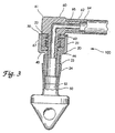
- FIG. 3 shows right angle adapter 60 opening entrance "S" slit 16 of valve member 10.
- Adapter 60 has a rigid injection molded right angle body portion 61, with rear stem 62 and front stem 63. Connected onto rear stem 62 is flexible PVC connecting tube 64.
- Rear stem 62 has lumen 65 and front stem 63 has lumen 66.
- front stem 63 opens entrance seal 10, it seats into annular seating portion 23 of housing member 20.
- the underside surface 67 on right angle body portion 60 seats firmly on top surface 33 of retainer cap 20. So positioned, lumen 66 of front stem 63 accesses central lumen 51 of tubular/tip member 50.
- Right angle adapter 60 thus accesses lumen 51 of tubular/tip member 50 to deliver enteral formula or the administration of liquid medication into the body of a patient.
- Adapter 60 via connecting tube 64, can be attached to any medication or enteral delivery set whether administered by gravity or a pump delivery method.
- adapter 60 can act as a decompression tube to vent gastrostomy port 100 and relieve pressure build up which tends to occur when a gastrostomy feeding port is left in place over a long period of time.
- adapter 60 is removed and valve member 10 closes instantaneously to prevent reflux. Sealing is instantaneous due to compression collar 21 which acts to positively return leaves 17 and 18 to their normally closed position.
- Adapter 60 can be repeatedly inserted as needed over many months of use without the valve leaking or stretching out of shape.
- a right angle adapter can be inserted into the valve S-slit 16 as needed.
- the valve remains in its normally closed positively sealed position due to compressive collar 21 acting to bias valve member 10 closed and keeping it closed to prevent reflux of stomach contents out through valve member 10.
- feeding port 100 requires no internal anti-reflux valve, which might become clogged or stuck. It also does not need any removable valve cap or any stoppers or back up closure caps to add bulk to the outside profile. All functions can take place directly through the entrance seal, thus eliminating the need for anti-reflux valves, valve caps, stoppers, closure caps, or complicated decompression tubes.
- FIG. 4a shows resilient valve member 10 prior to positioning within cavity 22.
- valve member 10 is uncompressed and is larger in dimension than cavity 22.
- FIG. 4a further shows how chamfered edge 14 allows for the introduction of cylindrical wall portion 12 into cavity 22 such that valve member 10 can then be press fit into cavity 22 without buckling or distorting diaphragm portion 11.
- FIG 4b showing resilient valve member 10, after it has been press fitted into cavity 22, with retainer cap 30 mounted thereon to maintain valve member 10 within cavity 22.
Landscapes
- Health & Medical Sciences (AREA)
- Life Sciences & Earth Sciences (AREA)
- Animal Behavior & Ethology (AREA)
- General Health & Medical Sciences (AREA)
- Public Health (AREA)
- Veterinary Medicine (AREA)
- Gastroenterology & Hepatology (AREA)
- Infusion, Injection, And Reservoir Apparatuses (AREA)
- Media Introduction/Drainage Providing Device (AREA)
- Jellies, Jams, And Syrups (AREA)
- Feeding And Controlling Fuel (AREA)
Claims (5)
- Ventil für einen Verweil-Katheter, mit:wobei das federnde Ventilteil (10) komprimiert in den das Ventilteil aufnehmenden Hohlraum (22) eingepaßt ist durch Verschieben des äußeren Wandabschnittes in den Hohlraum (22), um dadurch den äußeren Umfangsrand dimensionsmäßig zusammenzudrücken und in den Hohlraum zu passen, wobei der Kompressionskragenabschnitt des Ventilgehäuses einwärts gegen den äußeren Umfangsrand des Membranabschnittes drückt, um seitliche Kompressionskräfte gegen den Membranabschnitt (11) aufzubringen und dadurch den Schlitz (16) in Richtung auf eine normal geschlossene Stellung zu beaufschlagen, wobei die Fixierkappe (30) von dem federnden Ventilteil (10) um einen Spalt entfernt ist;einem Ventilgehäuse (20), welches einen inneren Durchgang da hindurch definiert zum Bereitstellen einer Fluid-Verbindung in den Katheter, wobei das Gehäuse (20) aufweist:einen steifen Kompressionskragenabschitt (21), der einen ein Ventilteil aufnehmenden Hohlraum (22) in dem Ventilgehäuse definiert, das wahlweise mit dem Katheter verbindbar ist,eine Fixierkappe (30), die eine Öffnung definiert, welche den das Ventilteil aufnehmenden Hohlraum (22) durchschneidet; undeinen ringförmigen Fortsatz (24);ein federndes Ventilteil (10), das einen Membranabschnitt (11) einschließt, der einen Schlitz (16) da hindurch definiert und einen äußeren Umfangsrand besitzt, der im wesentlichen der Gestalt des das Ventilteil aufnehmenden Hohlraums entspricht, aber dimensionsmäßig größer ist als der Hohlraum (22), wenn das federnde Ventilteil (10) unkomprimiert ist, wobei der äußere Wandabschnitt von dem äußeren Umfangsrand hinweg verläuft und sich im wesentlichen der Gestalt des Hohlraums (22) anpasst; und
und
wobei schließlich das federnde Ventilteil (10) zwischen dem Fortsatz (24) und der Fixierkappe (30) positioniert ist. - Ventil nach Anspruch 1, bei dem der ein Ventilteil aufnehmende Hohlraum/Abschnitt und der federnde Ventilteil im wesentlichen von zylindrischer Gestalt sind.
- Ventil nach Anspruch 1 oder 2, bei dem der Schlitz in dem Membranabschnitt von gekrümmter Gestalt ist.
- Ventil nach einem der Ansprüche 1 bis 3, bei dem der Schlitz in dem Membranabschnitt die Gestalt eines "S" hat.
- Apparat mit einem Ventil nach einem der Ansprüche 1 bis 4 und einem rohrförmigen Teil, welches mit dem Ansatz in Eingriff steht.
Applications Claiming Priority (3)
| Application Number | Priority Date | Filing Date | Title |
|---|---|---|---|
| US08/202,443 US5718691A (en) | 1994-02-28 | 1994-02-28 | Gastrostomy feeding port with a positively sealing one-way entrance valve |
| US202443 | 1994-02-28 | ||
| EP95911987A EP0751793B1 (de) | 1994-02-28 | 1995-02-28 | Gastrostomieernährungsport mit einem einwegventil |
Related Parent Applications (1)
| Application Number | Title | Priority Date | Filing Date |
|---|---|---|---|
| EP95911987A Division EP0751793B1 (de) | 1994-02-28 | 1995-02-28 | Gastrostomieernährungsport mit einem einwegventil |
Publications (3)
| Publication Number | Publication Date |
|---|---|
| EP1249220A2 EP1249220A2 (de) | 2002-10-16 |
| EP1249220A3 EP1249220A3 (de) | 2002-10-30 |
| EP1249220B1 true EP1249220B1 (de) | 2005-05-18 |
Family
ID=22749892
Family Applications (2)
| Application Number | Title | Priority Date | Filing Date |
|---|---|---|---|
| EP02077611A Expired - Lifetime EP1249220B1 (de) | 1994-02-28 | 1995-02-28 | Gastrostomieernährungsport mit einem Einwegventil |
| EP95911987A Expired - Lifetime EP0751793B1 (de) | 1994-02-28 | 1995-02-28 | Gastrostomieernährungsport mit einem einwegventil |
Family Applications After (1)
| Application Number | Title | Priority Date | Filing Date |
|---|---|---|---|
| EP95911987A Expired - Lifetime EP0751793B1 (de) | 1994-02-28 | 1995-02-28 | Gastrostomieernährungsport mit einem einwegventil |
Country Status (10)
| Country | Link |
|---|---|
| US (1) | US5718691A (de) |
| EP (2) | EP1249220B1 (de) |
| JP (1) | JPH09509596A (de) |
| AT (2) | ATE295713T1 (de) |
| AU (1) | AU688875B2 (de) |
| CA (1) | CA2184275C (de) |
| DE (2) | DE69528162T2 (de) |
| DK (1) | DK0751793T3 (de) |
| ES (1) | ES2182893T3 (de) |
| WO (1) | WO1995023001A1 (de) |
Families Citing this family (32)
| Publication number | Priority date | Publication date | Assignee | Title |
|---|---|---|---|---|
| US5716347A (en) * | 1994-02-28 | 1998-02-10 | Wilson-Cook Medical Inc. | Gastrostomy feeding ports with positively sealing entrance valves |
| US6019746A (en) * | 1996-05-17 | 2000-02-01 | Applied Medical Technology, Inc. | Low profile balloon feeding device |
| US6223070B1 (en) * | 1998-03-16 | 2001-04-24 | Cook, Inc. | Indwelling catheter |
| US6546280B2 (en) | 1996-06-18 | 2003-04-08 | Cook Incorporated | Indwelling catheter |
| US5727555A (en) * | 1996-06-18 | 1998-03-17 | Cook Incorporated | Indwelling catheter |
| US6165168A (en) * | 1997-09-02 | 2000-12-26 | Russo; Ronald D. | Closed system adapter for catheters |
| US6030361A (en) * | 1999-01-25 | 2000-02-29 | Miyashiro; Augusto M. | Gastrostomy apparatus |
| US7101353B2 (en) * | 1999-12-30 | 2006-09-05 | Cook Vascular Incorporated | Splittable medical valve |
| US6328720B1 (en) | 2000-02-18 | 2001-12-11 | Zevex, Inc. | Low-profile enterostomy device |
| US6908449B2 (en) * | 2000-12-19 | 2005-06-21 | Kimberly-Clark Worldwide, Inc. | Sealing valve assembly for medical products |
| US6767340B2 (en) | 2000-12-19 | 2004-07-27 | Kimberly-Clark Worldwide, Inc. | Sealing valve assembly for medical products |
| US20050187524A1 (en) * | 2000-12-19 | 2005-08-25 | Willis Allan F. | Sealing valve assembly for medical products |
| US7147121B2 (en) * | 2003-04-03 | 2006-12-12 | Abc Development Inc. | Valve for non-spill cup |
| US20050033269A1 (en) * | 2003-08-06 | 2005-02-10 | Kimberly-Clark Worldwide, Inc. | Ferrule and enteral tube incorporating a ferrule |
| US20050033268A1 (en) * | 2003-08-06 | 2005-02-10 | Kimberly-Clark Worldwide, Inc. | Connector with protrusion adapted for interconnection with second member |
| US20050033267A1 (en) * | 2003-08-06 | 2005-02-10 | Kimberly-Clark Worldwide, Inc. | Connector with connection mechanism adapted for releasable interconnection with tube |
| US20050171468A1 (en) * | 2004-02-04 | 2005-08-04 | Wood Scott D. | Gastric aspirate intestinal feeding tube |
| US8096300B2 (en) * | 2004-12-03 | 2012-01-17 | Dale Medical Products, Inc. | Endotracheal tube holder |
| US7914497B2 (en) * | 2005-01-26 | 2011-03-29 | Radius International Limited Partnership | Catheter |
| FR2903302B1 (fr) * | 2006-07-06 | 2008-08-29 | Stephane Regnault | Montage d'un tube de gastrostomie sur une embase et bouton de gastrostomie |
| JP4994775B2 (ja) | 2006-10-12 | 2012-08-08 | 日本コヴィディエン株式会社 | 針先保護具 |
| JP2009153764A (ja) * | 2007-12-27 | 2009-07-16 | Nippon Sherwood Medical Industries Ltd | 内視鏡用挿入補助具 |
| CN103269731B (zh) | 2010-10-01 | 2015-11-25 | 泽维克斯公司 | 用于基于管材料性能来提高蠕动泵系统的精确度的方法 |
| US8486024B2 (en) | 2011-04-27 | 2013-07-16 | Covidien Lp | Safety IV catheter assemblies |
| US8628497B2 (en) | 2011-09-26 | 2014-01-14 | Covidien Lp | Safety catheter |
| EP2760521B1 (de) | 2011-09-26 | 2016-01-06 | Covidien LP | Sicherheits-iv-katheter und nadelanordnung |
| WO2013056223A1 (en) | 2011-10-14 | 2013-04-18 | Covidien Lp | Safety iv catheter assembly |
| JP6456067B2 (ja) * | 2014-07-30 | 2019-01-23 | 株式会社藤井合金製作所 | 流路接続装置 |
| US20180008810A1 (en) * | 2015-02-20 | 2018-01-11 | Cendres+Métaux Sa | Valve device, removing tool and mounting tool |
| JP6719198B2 (ja) * | 2015-12-11 | 2020-07-08 | 株式会社Eviジャパン | 固定構造 |
| CN109172107B8 (zh) * | 2018-11-06 | 2024-07-16 | 中国人民解放军总医院第六医学中心 | 一种无缝连接肠内营养管的造口袋 |
| CN114748019B (zh) * | 2022-04-11 | 2023-07-18 | 新光维医疗科技(苏州)股份有限公司 | 可调式密封阀、控制方法及内窥镜系统 |
Citations (1)
| Publication number | Priority date | Publication date | Assignee | Title |
|---|---|---|---|---|
| EP0442194A2 (de) * | 1990-02-13 | 1991-08-21 | Daig Corporation | Zylindrischer Stopfen zum Abdichten eines Führungsdrahtes |
Family Cites Families (20)
| Publication number | Priority date | Publication date | Assignee | Title |
|---|---|---|---|---|
| US3853127A (en) * | 1973-04-03 | 1974-12-10 | R Spademan | Elastic sealing member |
| US3977400A (en) * | 1974-11-29 | 1976-08-31 | Deseret Pharmaceutical Co., Inc. | Catheter placement unit with resilient sleeve and manual sleeve closure |
| US4315513A (en) * | 1980-03-10 | 1982-02-16 | Nawash Michael S | Gastrostomy and other percutaneous transport tubes |
| US4351328A (en) * | 1980-03-27 | 1982-09-28 | Sontek Industries, Inc. | Simultaneous respiration and endotracheal suctioning of a critically ill patient |
| US4430081A (en) * | 1981-01-06 | 1984-02-07 | Cook, Inc. | Hemostasis sheath |
| JPS61154679A (ja) * | 1984-12-28 | 1986-07-14 | テルモ株式会社 | 体内導入套管 |
| US5251873B1 (en) * | 1992-06-04 | 1995-05-02 | Vernay Laboratories | Medical coupling site. |
| US4850953A (en) * | 1987-07-27 | 1989-07-25 | Habley Medical Technology Corporation | Gastrostomy valve |
| EP0354947B1 (de) * | 1988-01-25 | 1994-07-20 | BAXTER INTERNATIONAL INC. (a Delaware corporation) | Vorgeschlitzte injektionsvorrichtung sowie konische kanüle |
| US4944732A (en) * | 1988-08-15 | 1990-07-31 | Sandoz Nutrition Corporation | Gastrostomy feeding port |
| US5000745A (en) * | 1988-11-18 | 1991-03-19 | Edward Weck Incorporated | Hemostatis valve |
| US5073166A (en) * | 1989-02-15 | 1991-12-17 | Medical Innovations Corporation | Method and apparatus for emplacement of a gastrostomy catheter |
| US5125897A (en) * | 1990-04-27 | 1992-06-30 | Corpak, Inc. | Gastrostomy device with one-way valve and cuff pin |
| US5114408A (en) * | 1990-10-18 | 1992-05-19 | Daig Corporation | Universal hemostasis valve having improved sealing characteristics |
| JPH04170966A (ja) * | 1990-11-01 | 1992-06-18 | Nippon Sherwood Kk | カテーテルイントロジューサ止血弁の弁膜体 |
| US5125903A (en) * | 1991-08-01 | 1992-06-30 | Medtronic, Inc. | Hemostasis valve |
| US5279571A (en) * | 1991-12-30 | 1994-01-18 | Abbott Laboratories | Access site for fluid delivery system |
| US5261885A (en) * | 1992-07-14 | 1993-11-16 | Cook Pacemaker Corporation | Valved catheter |
| US5336203A (en) * | 1993-05-28 | 1994-08-09 | Abbott Laboratories | Low profile gastrostomy device with dome |
| US5330437A (en) * | 1993-11-12 | 1994-07-19 | Ethicon Endo-Surgery | Self sealing flexible elastomeric valve and trocar assembly for incorporating same |
-
1994
- 1994-02-28 US US08/202,443 patent/US5718691A/en not_active Expired - Lifetime
-
1995
- 1995-02-28 WO PCT/US1995/002474 patent/WO1995023001A1/en not_active Ceased
- 1995-02-28 DE DE69528162T patent/DE69528162T2/de not_active Expired - Lifetime
- 1995-02-28 JP JP7522521A patent/JPH09509596A/ja active Pending
- 1995-02-28 AT AT02077611T patent/ATE295713T1/de not_active IP Right Cessation
- 1995-02-28 CA CA002184275A patent/CA2184275C/en not_active Expired - Lifetime
- 1995-02-28 EP EP02077611A patent/EP1249220B1/de not_active Expired - Lifetime
- 1995-02-28 DE DE69534219T patent/DE69534219D1/de not_active Expired - Lifetime
- 1995-02-28 AT AT95911987T patent/ATE223742T1/de not_active IP Right Cessation
- 1995-02-28 AU AU19352/95A patent/AU688875B2/en not_active Expired
- 1995-02-28 EP EP95911987A patent/EP0751793B1/de not_active Expired - Lifetime
- 1995-02-28 ES ES95911987T patent/ES2182893T3/es not_active Expired - Lifetime
- 1995-02-28 DK DK95911987T patent/DK0751793T3/da active
Patent Citations (1)
| Publication number | Priority date | Publication date | Assignee | Title |
|---|---|---|---|---|
| EP0442194A2 (de) * | 1990-02-13 | 1991-08-21 | Daig Corporation | Zylindrischer Stopfen zum Abdichten eines Führungsdrahtes |
Also Published As
| Publication number | Publication date |
|---|---|
| DE69534219D1 (de) | 2005-06-23 |
| DE69528162T2 (de) | 2003-05-28 |
| JPH09509596A (ja) | 1997-09-30 |
| ATE295713T1 (de) | 2005-06-15 |
| US5718691A (en) | 1998-02-17 |
| EP0751793A4 (de) | 1997-11-19 |
| ES2182893T3 (es) | 2003-03-16 |
| CA2184275C (en) | 2006-06-06 |
| EP1249220A3 (de) | 2002-10-30 |
| EP0751793A1 (de) | 1997-01-08 |
| DE69528162D1 (de) | 2002-10-17 |
| CA2184275A1 (en) | 1995-08-31 |
| DK0751793T3 (da) | 2003-01-13 |
| AU688875B2 (en) | 1998-03-19 |
| ATE223742T1 (de) | 2002-09-15 |
| WO1995023001A1 (en) | 1995-08-31 |
| EP1249220A2 (de) | 2002-10-16 |
| AU1935295A (en) | 1995-09-11 |
| EP0751793B1 (de) | 2002-09-11 |
Similar Documents
| Publication | Publication Date | Title |
|---|---|---|
| EP1249220B1 (de) | Gastrostomieernährungsport mit einem Einwegventil | |
| EP0825881B1 (de) | Gastrostomie-ernährungsöffnungen mit einwandfrei abdichtenden eintrittsventilen | |
| US5720734A (en) | Gastrostomy feeding ports | |
| US6165168A (en) | Closed system adapter for catheters | |
| US4944732A (en) | Gastrostomy feeding port | |
| US6979322B2 (en) | Low profile adaptor for use with a medical catheter | |
| CA2143646C (en) | Low profile gastrostomy device with dome | |
| US4959055A (en) | Retainer for a percutaneous tube | |
| EP0701454A1 (de) | Gastrostomie vorrichtung mit quer geschlitzte einwegventil | |
| AU2001224507B2 (en) | Closed system adapter for catheters | |
| AU2001224507A1 (en) | Closed system adapter for catheters | |
| US4004589A (en) | Ostomy irrigation apparatus | |
| JPH0629502U (ja) | 内視鏡用閉塞栓 |
Legal Events
| Date | Code | Title | Description |
|---|---|---|---|
| PUAI | Public reference made under article 153(3) epc to a published international application that has entered the european phase |
Free format text: ORIGINAL CODE: 0009012 |
|
| PUAL | Search report despatched |
Free format text: ORIGINAL CODE: 0009013 |
|
| 17P | Request for examination filed |
Effective date: 20020712 |
|
| AC | Divisional application: reference to earlier application |
Ref document number: 751793 Country of ref document: EP |
|
| AK | Designated contracting states |
Kind code of ref document: A2 Designated state(s): AT BE CH DE DK ES FR GB GR IE IT LI LU MC NL PT SE |
|
| AK | Designated contracting states |
Kind code of ref document: A3 Designated state(s): AT BE CH DE DK ES FR GB GR IE IT LI LU MC NL PT SE |
|
| AKX | Designation fees paid |
Designated state(s): AT BE CH DE DK ES FR GB GR IE IT LI LU MC NL PT SE |
|
| 17Q | First examination report despatched |
Effective date: 20040115 |
|
| GRAP | Despatch of communication of intention to grant a patent |
Free format text: ORIGINAL CODE: EPIDOSNIGR1 |
|
| GRAS | Grant fee paid |
Free format text: ORIGINAL CODE: EPIDOSNIGR3 |
|
| GRAA | (expected) grant |
Free format text: ORIGINAL CODE: 0009210 |
|
| AC | Divisional application: reference to earlier application |
Ref document number: 0751793 Country of ref document: EP Kind code of ref document: P |
|
| AK | Designated contracting states |
Kind code of ref document: B1 Designated state(s): AT BE CH DE DK ES FR GB GR IE IT LI LU MC NL PT SE |
|
| PG25 | Lapsed in a contracting state [announced via postgrant information from national office to epo] |
Ref country code: IT Free format text: LAPSE BECAUSE OF FAILURE TO SUBMIT A TRANSLATION OF THE DESCRIPTION OR TO PAY THE FEE WITHIN THE PRESCRIBED TIME-LIMIT;WARNING: LAPSES OF ITALIAN PATENTS WITH EFFECTIVE DATE BEFORE 2007 MAY HAVE OCCURRED AT ANY TIME BEFORE 2007. THE CORRECT EFFECTIVE DATE MAY BE DIFFERENT FROM THE ONE RECORDED. Effective date: 20050518 Ref country code: AT Free format text: LAPSE BECAUSE OF FAILURE TO SUBMIT A TRANSLATION OF THE DESCRIPTION OR TO PAY THE FEE WITHIN THE PRESCRIBED TIME-LIMIT Effective date: 20050518 Ref country code: CH Free format text: LAPSE BECAUSE OF FAILURE TO SUBMIT A TRANSLATION OF THE DESCRIPTION OR TO PAY THE FEE WITHIN THE PRESCRIBED TIME-LIMIT Effective date: 20050518 Ref country code: NL Free format text: LAPSE BECAUSE OF FAILURE TO SUBMIT A TRANSLATION OF THE DESCRIPTION OR TO PAY THE FEE WITHIN THE PRESCRIBED TIME-LIMIT Effective date: 20050518 Ref country code: BE Free format text: LAPSE BECAUSE OF FAILURE TO SUBMIT A TRANSLATION OF THE DESCRIPTION OR TO PAY THE FEE WITHIN THE PRESCRIBED TIME-LIMIT Effective date: 20050518 Ref country code: LI Free format text: LAPSE BECAUSE OF FAILURE TO SUBMIT A TRANSLATION OF THE DESCRIPTION OR TO PAY THE FEE WITHIN THE PRESCRIBED TIME-LIMIT Effective date: 20050518 |
|
| REG | Reference to a national code |
Ref country code: GB Ref legal event code: FG4D |
|
| REG | Reference to a national code |
Ref country code: CH Ref legal event code: EP |
|
| REG | Reference to a national code |
Ref country code: IE Ref legal event code: FG4D |
|
| REF | Corresponds to: |
Ref document number: 69534219 Country of ref document: DE Date of ref document: 20050623 Kind code of ref document: P |
|
| PG25 | Lapsed in a contracting state [announced via postgrant information from national office to epo] |
Ref country code: GR Free format text: LAPSE BECAUSE OF FAILURE TO SUBMIT A TRANSLATION OF THE DESCRIPTION OR TO PAY THE FEE WITHIN THE PRESCRIBED TIME-LIMIT Effective date: 20050818 Ref country code: DK Free format text: LAPSE BECAUSE OF FAILURE TO SUBMIT A TRANSLATION OF THE DESCRIPTION OR TO PAY THE FEE WITHIN THE PRESCRIBED TIME-LIMIT Effective date: 20050818 Ref country code: SE Free format text: LAPSE BECAUSE OF FAILURE TO SUBMIT A TRANSLATION OF THE DESCRIPTION OR TO PAY THE FEE WITHIN THE PRESCRIBED TIME-LIMIT Effective date: 20050818 |
|
| PG25 | Lapsed in a contracting state [announced via postgrant information from national office to epo] |
Ref country code: DE Free format text: LAPSE BECAUSE OF FAILURE TO SUBMIT A TRANSLATION OF THE DESCRIPTION OR TO PAY THE FEE WITHIN THE PRESCRIBED TIME-LIMIT Effective date: 20050819 |
|
| PG25 | Lapsed in a contracting state [announced via postgrant information from national office to epo] |
Ref country code: ES Free format text: LAPSE BECAUSE OF FAILURE TO SUBMIT A TRANSLATION OF THE DESCRIPTION OR TO PAY THE FEE WITHIN THE PRESCRIBED TIME-LIMIT Effective date: 20050829 |
|
| PG25 | Lapsed in a contracting state [announced via postgrant information from national office to epo] |
Ref country code: PT Free format text: LAPSE BECAUSE OF FAILURE TO SUBMIT A TRANSLATION OF THE DESCRIPTION OR TO PAY THE FEE WITHIN THE PRESCRIBED TIME-LIMIT Effective date: 20051024 |
|
| REG | Reference to a national code |
Ref country code: CH Ref legal event code: PL |
|
| NLV1 | Nl: lapsed or annulled due to failure to fulfill the requirements of art. 29p and 29m of the patents act | ||
| PG25 | Lapsed in a contracting state [announced via postgrant information from national office to epo] |
Ref country code: LU Free format text: LAPSE BECAUSE OF NON-PAYMENT OF DUE FEES Effective date: 20060228 Ref country code: IE Free format text: LAPSE BECAUSE OF NON-PAYMENT OF DUE FEES Effective date: 20060228 Ref country code: MC Free format text: LAPSE BECAUSE OF NON-PAYMENT OF DUE FEES Effective date: 20060228 |
|
| PLBE | No opposition filed within time limit |
Free format text: ORIGINAL CODE: 0009261 |
|
| STAA | Information on the status of an ep patent application or granted ep patent |
Free format text: STATUS: NO OPPOSITION FILED WITHIN TIME LIMIT |
|
| 26N | No opposition filed |
Effective date: 20060221 |
|
| EN | Fr: translation not filed | ||
| REG | Reference to a national code |
Ref country code: IE Ref legal event code: MM4A |
|
| PG25 | Lapsed in a contracting state [announced via postgrant information from national office to epo] |
Ref country code: FR Free format text: LAPSE BECAUSE OF FAILURE TO SUBMIT A TRANSLATION OF THE DESCRIPTION OR TO PAY THE FEE WITHIN THE PRESCRIBED TIME-LIMIT Effective date: 20050518 |
|
| PGFP | Annual fee paid to national office [announced via postgrant information from national office to epo] |
Ref country code: GB Payment date: 20140226 Year of fee payment: 20 |
|
| REG | Reference to a national code |
Ref country code: GB Ref legal event code: PE20 Expiry date: 20150227 |
|
| PG25 | Lapsed in a contracting state [announced via postgrant information from national office to epo] |
Ref country code: GB Free format text: LAPSE BECAUSE OF EXPIRATION OF PROTECTION Effective date: 20150227 |