EP1249621A2 - Dispositif de montage par serrage de structures porteuses - Google Patents
Dispositif de montage par serrage de structures porteuses Download PDFInfo
- Publication number
- EP1249621A2 EP1249621A2 EP02005167A EP02005167A EP1249621A2 EP 1249621 A2 EP1249621 A2 EP 1249621A2 EP 02005167 A EP02005167 A EP 02005167A EP 02005167 A EP02005167 A EP 02005167A EP 1249621 A2 EP1249621 A2 EP 1249621A2
- Authority
- EP
- European Patent Office
- Prior art keywords
- clamping
- clamping device
- contact
- bearing shell
- clamping element
- Prior art date
- Legal status (The legal status is an assumption and is not a legal conclusion. Google has not performed a legal analysis and makes no representation as to the accuracy of the status listed.)
- Granted
Links
- 239000000969 carrier Substances 0.000 claims description 10
- 238000006073 displacement reaction Methods 0.000 description 2
- 229910000831 Steel Inorganic materials 0.000 description 1
- 238000010521 absorption reaction Methods 0.000 description 1
- 238000004026 adhesive bonding Methods 0.000 description 1
- 230000005540 biological transmission Effects 0.000 description 1
- 230000008878 coupling Effects 0.000 description 1
- 238000010168 coupling process Methods 0.000 description 1
- 238000005859 coupling reaction Methods 0.000 description 1
- 238000011161 development Methods 0.000 description 1
- 230000018109 developmental process Effects 0.000 description 1
- 230000003993 interaction Effects 0.000 description 1
- 238000004519 manufacturing process Methods 0.000 description 1
- 239000000463 material Substances 0.000 description 1
- 238000000034 method Methods 0.000 description 1
- 239000010959 steel Substances 0.000 description 1
Images


Classifications
-
- E—FIXED CONSTRUCTIONS
- E01—CONSTRUCTION OF ROADS, RAILWAYS, OR BRIDGES
- E01D—CONSTRUCTION OF BRIDGES, ELEVATED ROADWAYS OR VIADUCTS; ASSEMBLY OF BRIDGES
- E01D19/00—Structural or constructional details of bridges
- E01D19/12—Grating or flooring for bridges; Fastening railway sleepers or tracks to bridges
-
- F—MECHANICAL ENGINEERING; LIGHTING; HEATING; WEAPONS; BLASTING
- F16—ENGINEERING ELEMENTS AND UNITS; GENERAL MEASURES FOR PRODUCING AND MAINTAINING EFFECTIVE FUNCTIONING OF MACHINES OR INSTALLATIONS; THERMAL INSULATION IN GENERAL
- F16B—DEVICES FOR FASTENING OR SECURING CONSTRUCTIONAL ELEMENTS OR MACHINE PARTS TOGETHER, e.g. NAILS, BOLTS, CIRCLIPS, CLAMPS, CLIPS OR WEDGES; JOINTS OR JOINTING
- F16B2/00—Friction-grip releasable fastenings
- F16B2/02—Clamps, i.e. with gripping action effected by positive means other than the inherent resistance to deformation of the material of the fastening
- F16B2/06—Clamps, i.e. with gripping action effected by positive means other than the inherent resistance to deformation of the material of the fastening external, i.e. with contracting action
- F16B2/065—Clamps, i.e. with gripping action effected by positive means other than the inherent resistance to deformation of the material of the fastening external, i.e. with contracting action using screw-thread elements
-
- B—PERFORMING OPERATIONS; TRANSPORTING
- B25—HAND TOOLS; PORTABLE POWER-DRIVEN TOOLS; MANIPULATORS
- B25B—TOOLS OR BENCH DEVICES NOT OTHERWISE PROVIDED FOR, FOR FASTENING, CONNECTING, DISENGAGING OR HOLDING
- B25B5/00—Clamps
- B25B5/16—Details, e.g. jaws, jaw attachments
-
- E—FIXED CONSTRUCTIONS
- E04—BUILDING
- E04G—SCAFFOLDING; FORMS; SHUTTERING; BUILDING IMPLEMENTS OR AIDS, OR THEIR USE; HANDLING BUILDING MATERIALS ON THE SITE; REPAIRING, BREAKING-UP OR OTHER WORK ON EXISTING BUILDINGS
- E04G7/00—Connections between parts of the scaffold
- E04G7/02—Connections between parts of the scaffold with separate coupling elements
- E04G7/06—Stiff scaffolding clamps for connecting scaffold members of common shape
- E04G7/08—Clamps for parallelly-arranged members
-
- F—MECHANICAL ENGINEERING; LIGHTING; HEATING; WEAPONS; BLASTING
- F16—ENGINEERING ELEMENTS AND UNITS; GENERAL MEASURES FOR PRODUCING AND MAINTAINING EFFECTIVE FUNCTIONING OF MACHINES OR INSTALLATIONS; THERMAL INSULATION IN GENERAL
- F16B—DEVICES FOR FASTENING OR SECURING CONSTRUCTIONAL ELEMENTS OR MACHINE PARTS TOGETHER, e.g. NAILS, BOLTS, CIRCLIPS, CLAMPS, CLIPS OR WEDGES; JOINTS OR JOINTING
- F16B2/00—Friction-grip releasable fastenings
- F16B2/005—Means to increase the friction-coefficient
-
- F—MECHANICAL ENGINEERING; LIGHTING; HEATING; WEAPONS; BLASTING
- F16—ENGINEERING ELEMENTS AND UNITS; GENERAL MEASURES FOR PRODUCING AND MAINTAINING EFFECTIVE FUNCTIONING OF MACHINES OR INSTALLATIONS; THERMAL INSULATION IN GENERAL
- F16B—DEVICES FOR FASTENING OR SECURING CONSTRUCTIONAL ELEMENTS OR MACHINE PARTS TOGETHER, e.g. NAILS, BOLTS, CIRCLIPS, CLAMPS, CLIPS OR WEDGES; JOINTS OR JOINTING
- F16B2200/00—Constructional details of connections not covered for in other groups of this subclass
- F16B2200/40—Clamping arrangements where clamping parts are received in recesses of elements to be connected
-
- Y—GENERAL TAGGING OF NEW TECHNOLOGICAL DEVELOPMENTS; GENERAL TAGGING OF CROSS-SECTIONAL TECHNOLOGIES SPANNING OVER SEVERAL SECTIONS OF THE IPC; TECHNICAL SUBJECTS COVERED BY FORMER USPC CROSS-REFERENCE ART COLLECTIONS [XRACs] AND DIGESTS
- Y10—TECHNICAL SUBJECTS COVERED BY FORMER USPC
- Y10S—TECHNICAL SUBJECTS COVERED BY FORMER USPC CROSS-REFERENCE ART COLLECTIONS [XRACs] AND DIGESTS
- Y10S403/00—Joints and connections
- Y10S403/09—Adjustable clamp
-
- Y—GENERAL TAGGING OF NEW TECHNOLOGICAL DEVELOPMENTS; GENERAL TAGGING OF CROSS-SECTIONAL TECHNOLOGIES SPANNING OVER SEVERAL SECTIONS OF THE IPC; TECHNICAL SUBJECTS COVERED BY FORMER USPC CROSS-REFERENCE ART COLLECTIONS [XRACs] AND DIGESTS
- Y10—TECHNICAL SUBJECTS COVERED BY FORMER USPC
- Y10T—TECHNICAL SUBJECTS COVERED BY FORMER US CLASSIFICATION
- Y10T403/00—Joints and connections
- Y10T403/33—Transverse rod to spaced plate surfaces
- Y10T403/335—Retainer utilizes or abuts plural plates
-
- Y—GENERAL TAGGING OF NEW TECHNOLOGICAL DEVELOPMENTS; GENERAL TAGGING OF CROSS-SECTIONAL TECHNOLOGIES SPANNING OVER SEVERAL SECTIONS OF THE IPC; TECHNICAL SUBJECTS COVERED BY FORMER USPC CROSS-REFERENCE ART COLLECTIONS [XRACs] AND DIGESTS
- Y10—TECHNICAL SUBJECTS COVERED BY FORMER USPC
- Y10T—TECHNICAL SUBJECTS COVERED BY FORMER US CLASSIFICATION
- Y10T403/00—Joints and connections
- Y10T403/71—Rod side to plate or side
- Y10T403/7123—Traversed by connector
Definitions
- the invention relates to a clamping device for releasable connection of components with supports or for detachable connection of carriers.
- Such clamping devices are used for example there where the beams cannot be welded together or the carriers must be releasably connected to one another so that these can be reused.
- These carriers can in principle any shape, for example a U-shaped a T or a double T-shaped cross section exhibit. These profiles often have flanges with chamfered Surfaces, especially on the inner surfaces. Is the clamping device on beveled carrier flanges or bevelled contact surfaces of components with the help of them the carriers are connected to each other, can at Applying a clamping force or clamping force to the clamping device and the carrier or the component due to the non-parallel shift mutual contact surfaces to each other.
- Clamping element of the clamping device one to the beveled surface of the flange or the component in opposite directions has as a contact surface in order to make the contact surface parallel of the clamping element to the contact surface of the carrier or of the component. So for each special contact surface an associated clamping device is provided become.
- the invention is therefore based on the object of a clamping device provide the disadvantages presented at least partially resolved by conventional clamping devices and especially with components and beams of different types Dimensions or bevels can be used.
- the invention already solves this problem with a clamping device for the detachable connection of components with supports or of carriers with each other with the features of claim 1.
- a clamping device includes a Clamping element on which a force can be exerted and one with the Clamping element interacting system element, one to one Carrier or a component has a contact surface.
- the clamping device comprises a means for coupling or connecting the Clamping element to the contact element, which is under the influence of Tension or clamping force an independent twisting and / or tilting of the contact element relative to the clamping element under the influence of the force exerted until the Contact surface of the contact element essentially parallel to the Carrier or the component is present.
- the invention is based on the idea of a clamping device the relative position of the clamping element to its associated Contact area changeable in such a way design that when creating the tensioning element with its associated Contact surface on the object to be clamped when applying the contact force of the clamping surface automatically aligns with the contact surface of the object to be clamped.
- This alignment of the contact surfaces enables each other optimal power transmission, so that in particular prevents can be that when applying the clamping force relative position of the individual parts to each other changed.
- the invention Clamping device is therefore flexible for many differently designed components and supports can be used, whereby through the self-adjustment of the clamping device described an optimal fixation is ensured that the Tension after the independent adjustment in normal Direction to the contact surfaces.
- a bearing shell can be used to couple the clamping element and contact element and a bearing body that can be received by the bearing shell be included, the bearing body being rotatable in the bearing shell is arranged.
- the bearing shell can either be on the clamping element or be formed on the contact element, while the associated Bearing body then on the contact element or in the other embodiment is formed on the clamping element.
- the mutual situation of the bearing shell and bearing body can be form-fitting, however Both parts must have at least one degree of freedom to each other exhibit.
- the clamping element can adapt to the geometry of the beam to be clamped and components can be adapted. For example, if a carrier which rests with a section on a component with this are jammed, it can be provided that the tensioning element is bridge-shaped, the bearing shell on arranged a first longitudinal end of the clamping element is.
- the clamping element can, for example, on the first longitudinal end on a support flange and with its second be pressed against the longitudinal end of the component, whereby the carrier and the component are jammed together.
- a contact element with a contact surface for contact is arranged on a carrier or a component.
- a particularly advantageous geometry results when a Bearing shell essentially perpendicular to the longitudinal extent of the Clamping element runs because of an enlarged contact surface can be provided to the part to be held.
- the bearing shell and the one that interacts with it Bearing body can be formed arbitrarily.
- a special one geometry that is easy to produce is obtained if the Bearing shell for receiving a substantially cylindrical one Bearing body is designed. It also ensures that between the bearing shell and the bearing body received by it a single degree of freedom exists in the axial Rotation of the bearing body in the cylindrical bearing shell consists.
- the Bearing shell essentially perpendicular to the longitudinal extent the bearing shell has a groove running with a on the bearing body attached nose to accommodate the parallel to the Forces extending longitudinal forces of the bearing body cooperate, the nose can also be designed as a web. This interaction of tongue and groove can also be used to determine the degree of freedom of the bearing body in the bearing shell become. It is understood that the groove is also on the bearing body and the nose can be formed on the bearing shell.
- the bearing shell each has a wall section at its lateral ends, with an associated wall section of the bearing body for Absorption of the axial forces on the bearing body, so that the bearing body is held laterally in the bearing shell becomes.
- the contact surface of the contact element is structured, for example, is corrugated.
- a contact element with an associated contact surface is rigid with the clamping element is connected, the distance between the contact surface of the contact element to the clamping element is adjustable. This can happen, for example, in that the contact element comprises at least one threaded bolt, which in a assigned thread can be screwed into the clamping element, the End surface of the threaded bolt removed from the clamping element as a contact surface of the contact element acts.
- a clamping screw through the Clamping element extends through, on the top of the Clamping element via a clamping plate and one acting on it Nut a clamping force can be exerted.
- a clamping screw through the Clamping element extends through, on the top of the Clamping element via a clamping plate and one acting on it Nut a clamping force can be exerted.
- Nut a clamping force can be exerted.
- To tilt the To prevent clamping plate on the clamping element can be provided be that the top of the clamping element in its longitudinal extent curved and the clamping plate for flat Support on the tensioning element is designed accordingly curved is.
- the invention also relates a clamping device for releasably connecting components with straps or for releasably connecting straps to a Clamping element to which a force can be exerted, which is applied to a the contact surface provided for the clamping element can be transferred to the carrier is.
- the contact surface has a threaded piece connected to the clamping element, the one-sided at least partially with its lateral surface in the clamping element is embedded and the opposite side protrudes essentially semi-cylindrical from the clamping element.
- the threaded piece thus forms the contact surface of the Clamping element.
- the threaded piece preferably consists of a hardenable material, especially a hardenable austenitic steel, such as X46Cr13.
- the threaded piece usually has a length / Diameter ratio of less than 10, preferably less than 5.
- connection between the wall element and the threaded piece can either be done for example by a snap connection, preferably a bowl-shaped recess with a Undercut is provided on the clamping element in the the threaded piece can be snapped into place, or by simply gluing it in of the threaded piece in the cup-shaped recess of the clamping element respectively.
- Other suitable connection methods are also possible.
- the present tensioning element is also preferably bridge-shaped formed and the threaded piece is on a first longitudinal side End of the clamping element arranged.
- the tensioning element can be on the first longitudinal end on a support flange and with its second longitudinal end are pressed against the component, whereby the carrier and the component can be clamped together are.
- this second solution also includes the previous ones mentioned developments for adjusting the clamping element realizable.
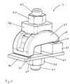
- FIG. 1 is a first embodiment of the invention Shown clamping device 1, with which a carrier 80 a component 90 is clamped.
- the clamping device consists in Essentially from a bridge-shaped clamping element 20, at the two longitudinal ends of each a contact element 30 is attached to the carrier 80 or the component 90 is present.
- a lateral pushing out of the contact elements 30 from the tensioning element prevent side wall sections 28 from Clamping element.
- the height of the foot of the tensioning element does not have to be exact equal to the height of the support 80 to a flat support to ensure the contact element 30 on the carrier 80, wherein for details on the explanations below is referred.
- Bolt 40 Extends to exert a tension force Bolt 40 essentially in the middle of the clamping element perpendicular to its longitudinal extent through this and the component 90 through, one on the underside of the component Nut 42 is screwed onto the bolt 40, the lower Clamping plate serves.
- the clamping plate 70 On the upper end of the bolt 40 is one Clamping plate 70 plugged on by means of another nut 41 to apply a clamping force to the clamping element the clamping plate 70 presses the force on the clamping element 20 transmits that the respective investment element against the Component 90 or the carrier 80 presses, which ultimately the Carrier 80 and component 90 are fixed to one another.
- FIG. 2 is a further clamping device designed according to the invention for clamping a carrier flange 81 to a component 90 shown in a side view, the bottom 82 runs parallel to the top 83 of the carrier flange, the bears flat against the top 92 of the component 90.
- the investment element 30, which is directly on the top 92 of the component 90 is present, is relative to the clamping element 20 easily in the Bearing shell twisted oriented to the contact element 30, which rests on the underside 82 of the carrier flange, since the bridge foot 21 does not fully compensate for the height of the support flange.
- FIG. 3 shows a side view Carrier flange 81 is not parallel to the top 83 running underside 82.
- the clamping element 1 is identical to that shown in FIG. 2.
- the shown in Fig. 3 Contact elements 30 are relative to the clamping element 20 orientated very differently, because that is in the drawing on the left side arranged element 30 during assembly of the clamping element 1 within the bearing shell of the clamping element 20 has rotated until the contact element 30 with its contact surface 31 completely on the underside 82 of the Carrier flange 81 rests.
- FIGS. 4a and 4b The structure of an exemplary tensioning element 20 is shown in FIGS FIGS. 4a and 4b.
- Two bridge-shaped side parts 25 are with each other in the area of the bridgeheads by means of transverse webs 26, 27 connected, whereby a bolt passage 24 is formed is that of the inner surfaces of the two side parts and the crossbars is limited.
- the side parts have on their top each have a curved sliding surface 23 on which the below Clamping plate explained in more detail is placed.
- one the bridgehead points to compensate for the thickness of the other Carrier flange held by a bridgehead has a foot section 21 on.
- the bearing shell surface is cylindrical, the width of the bearing shell opening D is less than 2 R, where R is the radius of the Cylinder shell is. This means that the bearing shell is a Has undercut that prevents an undercut the bearing shell shaped cylindrical bearing body falls down out of the bearing shell.
- FIG. 5 shows a contact element 30 designed as a cylindrical bearing body in a perspective view.
- the cylinder has a radius corresponding to the bearing shell R.
- the cylinder has a sectional plane which runs parallel to the cylinder axis.
- the bearing body is for the in the Figs. 1, 2 and 3 designed clamping element.
- the side surface 34 cooperates with an associated side section 28 of the bearing shell in order to absorb axial forces on the contact element 30.
- a corrugation is applied to the cut surface, the projections 33 of which, when the clamping force is applied, impress into the counter surface of the object to be held.
- FIG. 6 shows an alternative embodiment of a contact element 30 designed as a cylindrical bearing body in a side and a cross-sectional view, which is for use with one in the FIGS. 4a, 4b is shown.
- the cylinder again has a radius corresponding to the bearing shell R.
- the sectional plane for forming a contact surface 31 runs parallel to the cylinder axis A.
- the contact element 30 also has a circumferentially extending groove 32 approximately in the middle of its longitudinal extent, which is shown in FIG. 4a, 4b not shown nose cooperates in the bearing shell. In this case, the nose engages in the groove 32, as a result of which any forces that occur can be absorbed in the longitudinal direction of the contact element and thus lateral emergence of the contact element 30 from the bearing shell 22 can be prevented. Accordingly, side wall sections 28 on the tensioning element can be omitted.
- FIGS. 7a, b One cooperating with the clamping element and the clamping nut Clamping plate 70 is shown in detail in FIGS. 7a, b. It points corresponding to the curved surfaces 23 of the tensioning element assigned curved sliding surfaces 73.
- the bolt 40 of the assembled clamping element extends through the Pin bushing 74.
- Prevent guide bars 72 on the clamping plate the lateral displacement of the bolt to the clamping element.
- the guide bars act with the inner surfaces of the Side elements 25 together, see Fig. 1.
- Through the sliding surfaces 23, 73 ensures that the clamping disk is flat rests on the clamping element, even if the clamping element due to the rotation of a contact element in its bearing shell when tightening the clamping nut 41 tilts slightly to one side.
- the contact element is independent on the specific design of the clamping element and contact element held rotatably in the bearing shell 22. This is from crucial for the functioning of the invention Clamping device referred to below 3 is discussed. It is assumed that before Assembly of the clamping element, the two contact surfaces 31 of the Contact elements 30 in the clamping element 20 oriented parallel to each other are, this orientation of the top 92 of the component 90 should correspond. Now the carrier flange 81 to Component 90, as shown in Fig.
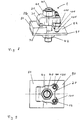
- FIG. 8 shows a further embodiment in a perspective drawing presented the invention.
- Bolt 40 through the clamping element 20 and the component 90, the nut 42 serves as the lower clamping plate.
- the Bolt passage in the clamping element corresponds approximately to the diameter of the bolt so that the use of an upper clamping plate can be dispensed with.
- the tensioning element does not lie in one in one Bearing shell arranged contact element on the component 90.
- two spaced threaded bolts 100 are arranged, each in an assigned thread in the clamping element are screwed in and are essentially parallel to the clamping thread bolt 40 extend to the top 92 of the component 90.
- the end faces 105 of the bolts facing component 90 100 accordingly replace the contact surface 31 of the right, e.g.
- a tool can be inserted into a hexagon recess 128, with which the threaded bolt 100 continues into the clamping element 20 are screwed in or otherwise unscrewed can, whereby the distance of the clamping element 20 to the component 90th can be adjusted.
- the set Distance between the clamping element 20 and the component 90 With the nuts 110 against the bottom of the clamping element can be rotated, the set Distance between the clamping element 20 and the component 90 fixed. Since the orientation of the contact surface 31 of the Contact element 30 to the underside 82 of the carrier flange automatically adjusts, the setting of the bolts 100 must Determining the distance of the clamping element 20 from the component 90 cannot be carried out exactly.
- the contact element 30 is relative to the threaded bolt 100 arranged so that its longitudinal extent essentially parallel to an imaginary connecting line lies between the bolts 100, wherein between the Connection line and the contact element 30 the implementation in Clamping element for the threaded bolt 40 is formed.
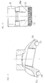
- this embodiment also consists of one Clamping element 20, which is connected to a carrier by a clamping plate 70, a component 90 or the like can be pressed.
- a no closer Bolt 40 shown generates the clamping force.
- the previous embodiments are in place of bearing elements rotatably received in the clamping element 20 now simply cylindrical threaded pieces 120, 122 in half-shell form Recesses 124, 126 of the clamping element 20 are used.
- the half-shell-shaped recesses 124, 126 extend essentially perpendicular to the direction of longitudinal extension of the clamping element 20 and are at the longitudinal ends on the one hand in the foot section 21 and on the other hand in the side wall section 28 provided.
- the threaded pieces 120, 122 are in the present embodiment glued into the recesses 124, 126. Because of that the clamping element 20 protruding area of the threaded pieces 120, 122 has the shape of a half cylinder, the Threaded pieces are not rotatably received in the clamping element 20 be like the contact elements in the previously described embodiments. Nevertheless, the spherical surfaces the threaded pieces 120, 122 the desired angular positions of the clamping element 20 in relation to the clamping plate 70 to adjust. The compensation required is therefore different high systems on component 80 or carrier 90 can be realized (see Figures 10a-10c).
- the form fit required for fixation is achieved by the thread of the threaded pieces 120, 122, which is due to of the contact pressure in the surfaces of the component 80 or the Press in carrier 90.
- the positive connection is produced it depends on the textured surface. So must it is not necessarily a threaded piece, but there are also other geometries for realizing the Angle adjustment with a corresponding surface structure usable. It is also possible, preferably semi-cylindrical To form contact surfaces on the clamping element 20, the with a suitable surface structure for the production of the Form fit are provided.
- a threaded piece represents one economically particularly interesting embodiment ready since the whole clamping element 20 does not have to be hardened and depending on the application, any thread pieces can be used are.
Landscapes
- Engineering & Computer Science (AREA)
- General Engineering & Computer Science (AREA)
- Mechanical Engineering (AREA)
- Architecture (AREA)
- Civil Engineering (AREA)
- Structural Engineering (AREA)
- Clamps And Clips (AREA)
- Bridges Or Land Bridges (AREA)
- Jigs For Machine Tools (AREA)
- Gripping Jigs, Holding Jigs, And Positioning Jigs (AREA)
- Joining Of Building Structures In Genera (AREA)
- Flanged Joints, Insulating Joints, And Other Joints (AREA)
- Electrical Discharge Machining, Electrochemical Machining, And Combined Machining (AREA)
- Apparatuses And Processes For Manufacturing Resistors (AREA)
- Catching Or Destruction (AREA)
- Load-Engaging Elements For Cranes (AREA)
- Soil Working Implements (AREA)
Applications Claiming Priority (4)
| Application Number | Priority Date | Filing Date | Title |
|---|---|---|---|
| DE10118714 | 2001-04-12 | ||
| DE10118714 | 2001-04-12 | ||
| DE10139226A DE10139226B4 (de) | 2001-04-12 | 2001-08-09 | Klemmvorrichtung zum Klemmen von Trägern |
| DE10139226 | 2001-08-09 |
Publications (3)
| Publication Number | Publication Date |
|---|---|
| EP1249621A2 true EP1249621A2 (fr) | 2002-10-16 |
| EP1249621A3 EP1249621A3 (fr) | 2003-05-28 |
| EP1249621B1 EP1249621B1 (fr) | 2007-01-03 |
Family
ID=26009098
Family Applications (1)
| Application Number | Title | Priority Date | Filing Date |
|---|---|---|---|
| EP02005167A Expired - Lifetime EP1249621B1 (fr) | 2001-04-12 | 2002-03-08 | Dispositif de montage par serrage de structures porteuses |
Country Status (8)
| Country | Link |
|---|---|
| US (1) | US7021855B2 (fr) |
| EP (1) | EP1249621B1 (fr) |
| JP (1) | JP4242601B2 (fr) |
| KR (1) | KR100772949B1 (fr) |
| CN (1) | CN1223737C (fr) |
| AT (1) | ATE350589T1 (fr) |
| DE (2) | DE20116015U1 (fr) |
| ES (1) | ES2280445T3 (fr) |
Cited By (4)
| Publication number | Priority date | Publication date | Assignee | Title |
|---|---|---|---|---|
| EP1946891A1 (fr) * | 2007-01-16 | 2008-07-23 | Tyco European Metal Framing Limited | Tête de serrage |
| DE102010020653A1 (de) * | 2010-05-06 | 2011-11-10 | Schunk Gmbh & Co. Kg Spann- Und Greiftechnik | Schlittenarretierung und Greifeinrichtung mit Schlittenarretierung |
| DE202012102995U1 (de) * | 2012-08-09 | 2013-11-13 | Rehau Ag + Co | Vorrichtung zur Fixierung von Schienen |
| US10415430B2 (en) | 2016-04-05 | 2019-09-17 | MTU Aero Engines AG | Coupling assembly for components of ceramic matrix composites for a turbine center frame |
Families Citing this family (31)
| Publication number | Priority date | Publication date | Assignee | Title |
|---|---|---|---|---|
| DE20213333U1 (de) * | 2002-08-30 | 2003-10-16 | C. O. Weise GmbH & Co. KG, 44369 Dortmund | Vorrichtung zur Befestigung eines Trägers eines Traggerüstes zur Schalung von Stahlverbundbrücken an einem Verbundträger der zu erstellenden Stahlverbundbrücke |
| EP1913913A3 (fr) | 2003-02-12 | 2008-05-28 | The Procter and Gamble Company | Partie centrale absorbante pour un article absorbant |
| ES2255370B1 (es) * | 2003-11-27 | 2007-07-16 | S.A. De Vera (Savera) | Brida deslizante de alta resistencia, para guias de ascensor. |
| CA2673327C (fr) * | 2006-12-22 | 2015-03-03 | Advanced Building Systems Pty Ltd | Clip non pivotant pour panneau |
| KR200445310Y1 (ko) * | 2007-05-21 | 2009-07-20 | 삼목정공주식회사 | 상승식 가설대 발판 고정용 클램프 |
| GB0802938D0 (en) * | 2008-02-19 | 2008-03-26 | Airbus Uk Ltd | Clamped friction joint |
| DE102009010428A1 (de) * | 2009-02-26 | 2010-09-02 | Sanitärtechnik Eisenberg GmbH | Vorrichtung zur Verbindung von Profilschienen mit Objekten |
| KR101220505B1 (ko) * | 2011-04-12 | 2013-01-10 | (주)비티엔지니어링 | 공작기계의 공작물 고정장치 |
| US8763922B2 (en) * | 2011-05-13 | 2014-07-01 | Vinylast, Inc. | Method and apparatus for installing a railing system |
| ES2421083B1 (es) * | 2012-02-22 | 2014-11-04 | S.A. De Vera (Savera) | Sistema de brida adaptable, para guías de ascensor |
| US8790059B2 (en) * | 2012-03-27 | 2014-07-29 | The Johns Hopkins University | Washer assembly for mounting on irregular surfaces |
| US9249813B2 (en) | 2012-10-01 | 2016-02-02 | Technifab, Inc. | Clamp |
| WO2014053868A1 (fr) * | 2012-10-01 | 2014-04-10 | Ev Ip Lp | Tête de serre-joint améliorée |
| US9788667B2 (en) * | 2013-07-16 | 2017-10-17 | Fasteners For Retail, Inc. | Lock for securing front rail to wire shelving |
| US9440744B2 (en) | 2013-10-17 | 2016-09-13 | The Boeing Company | Decompression panel assembly and method of equalizing air pressure differential |
| US9566759B2 (en) | 2013-10-25 | 2017-02-14 | The Boeing Company | Decompression panel for use in an aircraft assembly |
| US9499251B2 (en) | 2013-10-25 | 2016-11-22 | The Boeing Company | Decompression panel for use in an aircraft |
| US10071795B2 (en) * | 2013-10-25 | 2018-09-11 | The Boeing Company | Clamp device for use with a decompression panel in an aircraft assembly |
| USD817851S1 (en) | 2014-03-28 | 2018-05-15 | The Boeing Company | Decompression panel |
| EP2998590B1 (fr) | 2014-09-18 | 2018-11-28 | Airbus Operations GmbH | Pince de bride de faisceau, joint de faisceau structurel doté de telles pinces et procédé de formation dudit joint |
| EP2998588B1 (fr) | 2014-09-18 | 2019-06-12 | Airbus Operations GmbH | Joint de faisceau structurel doté de pinces de bride de faisceau et procédé de formation dudit joint |
| CN106363193B (zh) * | 2016-10-26 | 2018-07-03 | 重庆跃进机械厂有限公司 | 带混合边缘低速柴油机轴瓦内表面的加工方法 |
| DE102016122445B4 (de) * | 2016-11-22 | 2018-06-07 | Klaus Hofmann | Klemmvorrichtung |
| US10857638B2 (en) * | 2017-08-16 | 2020-12-08 | Michael W Stark | Vise clamp |
| US11384780B2 (en) * | 2017-12-13 | 2022-07-12 | Tamarack Solar Products, Inc. | Solar panel mounting configuration |
| CN108071632A (zh) * | 2017-12-29 | 2018-05-25 | 苏州瑞恩工业产品设计有限公司 | 一种轴卡紧固定装置 |
| CN108571444A (zh) * | 2018-06-30 | 2018-09-25 | 浙江荣鹏气动工具有限公司 | 一种可快速拆装的喷涂机往复柱塞泵 |
| USD997833S1 (en) * | 2020-10-30 | 2023-09-05 | Cypress Overland LLC | Removable support mount |
| CN112320679B (zh) * | 2020-11-20 | 2024-01-02 | 杭州莱本科技有限公司 | 移动作业的举升装置及其组装方法 |
| AU2021401315A1 (en) * | 2020-12-18 | 2023-07-06 | Preformed Line Products Co. | Photovoltaic panel cable mount arrangement |
| CN113982125A (zh) * | 2021-11-25 | 2022-01-28 | 江苏光银建设工程有限公司 | 用于工字钢的高效连接扣 |
Citations (1)
| Publication number | Priority date | Publication date | Assignee | Title |
|---|---|---|---|---|
| DE2245862A1 (de) | 1972-09-19 | 1974-05-22 | Siemens Ag | Klemmverbindung fuer profilschienen |
Family Cites Families (27)
| Publication number | Priority date | Publication date | Assignee | Title |
|---|---|---|---|---|
| US928827A (en) * | 1909-04-23 | 1909-07-20 | George Whitaker | Railroad-tie. |
| DE530053C (de) * | 1929-10-22 | 1931-07-20 | Josef Giza | Selbstspannende Schienenbefestigung |
| US1925867A (en) * | 1931-11-21 | 1933-09-05 | Westinghouse Elec Elevator Co | Elevator guide-rail supporting device |
| US1974628A (en) | 1932-04-16 | 1934-09-25 | Cleveland Crane Eng | Clamp |
| US2175453A (en) * | 1938-01-24 | 1939-10-10 | T B F Company | Clamp |
| GB629096A (en) * | 1946-08-22 | 1949-09-12 | Lindsay Ltd Henry | Improvements in or relating to clips or the like for securing flanges of rails, girders and like articles or structures to adjacent articles or structures |
| GB658500A (en) * | 1949-12-06 | 1951-10-10 | Lindsay Ltd Henry | Improvements in or relating to bolt adapters |
| US2905391A (en) * | 1956-01-27 | 1959-09-22 | Arthur I Appleton | Key type rail anchor |
| FR1448196A (fr) * | 1965-06-22 | 1966-01-28 | Ressorts Du Nord Sa | Attache élastique de rail |
| JPS5348512Y2 (fr) * | 1974-07-12 | 1978-11-20 | ||
| GB1530463A (en) | 1975-06-19 | 1978-11-01 | Lindsay Ltd Henry | Fastener devices |
| JPS5817843B2 (ja) * | 1980-08-25 | 1983-04-09 | 日本国有鉄道 | 鋼橋直結レ−ル締結装置 |
| JPS5880013A (ja) * | 1981-11-02 | 1983-05-14 | 安田 正雄 | 橋梁上の鉄道枕木締結装置 |
| US4553872A (en) | 1984-02-15 | 1985-11-19 | Fmc Corporation | Load cell clamping apparatus |
| JPS61169506A (ja) * | 1985-01-22 | 1986-07-31 | ショーボンド建設株式会社 | 床版と受桁取り合い接合方法 |
| GB8612280D0 (en) * | 1986-05-20 | 1986-06-25 | Lindsay Ltd Henry | Clamping device |
| EP0297133A1 (fr) | 1986-12-23 | 1989-01-04 | Tri Tool Inc. | Retenue a came d'elements d'outil |
| US5025987A (en) * | 1989-08-07 | 1991-06-25 | Harnischfeger Engineers, Inc. | Rail securement apparatus |
| DE8912630U1 (de) | 1989-10-24 | 1991-03-07 | Lisega GmbH, 2730 Zeven | Trägerklammer zur Halterung von Bauteilen, z.B. für Rohre u.dgl. |
| US5022291A (en) | 1990-08-06 | 1991-06-11 | Mcbain Corey L | Pliers having a pivotal jaw |
| US5135165A (en) * | 1991-05-08 | 1992-08-04 | Gantrex Limited | Device for aligning and clamping a rail |
| US5451116A (en) * | 1992-06-09 | 1995-09-19 | General Electric Company | Tripod plate for turbine flowpath |
| JP3840622B2 (ja) * | 1997-03-31 | 2006-11-01 | 東日本旅客鉄道株式会社 | 橋まくらぎ締着装置 |
| DE29915435U1 (de) * | 1999-09-03 | 2001-01-18 | Halfen GmbH & Co. Kommanditgesellschaft, 40764 Langenfeld | Trägerklemme |
| DE10025180A1 (de) | 2000-05-24 | 2001-11-29 | Moll Sys & Funktions Moebel | Halterung zur Fixierung eines Gegenstandes, insbesondere einer Leuchte |
| KR200256805Y1 (ko) * | 2001-09-03 | 2001-12-24 | 천원공업 주식회사 | 철도교량 침목 체결장치 |
| KR100843321B1 (ko) * | 2002-01-30 | 2008-07-04 | 이화케미칼 주식회사 | 궤도 방진장치 |
-
2001
- 2001-09-28 DE DE20116015U patent/DE20116015U1/de not_active Expired - Lifetime
-
2002
- 2002-03-08 AT AT02005167T patent/ATE350589T1/de not_active IP Right Cessation
- 2002-03-08 DE DE50209120T patent/DE50209120D1/de not_active Expired - Fee Related
- 2002-03-08 ES ES02005167T patent/ES2280445T3/es not_active Expired - Lifetime
- 2002-03-08 EP EP02005167A patent/EP1249621B1/fr not_active Expired - Lifetime
- 2002-04-10 CN CNB021058067A patent/CN1223737C/zh not_active Expired - Lifetime
- 2002-04-12 US US10/121,553 patent/US7021855B2/en not_active Expired - Lifetime
- 2002-04-12 KR KR1020020020038A patent/KR100772949B1/ko not_active Expired - Fee Related
- 2002-04-12 JP JP2002110777A patent/JP4242601B2/ja not_active Expired - Fee Related
Patent Citations (1)
| Publication number | Priority date | Publication date | Assignee | Title |
|---|---|---|---|---|
| DE2245862A1 (de) | 1972-09-19 | 1974-05-22 | Siemens Ag | Klemmverbindung fuer profilschienen |
Cited By (6)
| Publication number | Priority date | Publication date | Assignee | Title |
|---|---|---|---|---|
| EP1946891A1 (fr) * | 2007-01-16 | 2008-07-23 | Tyco European Metal Framing Limited | Tête de serrage |
| US8459624B2 (en) | 2007-01-16 | 2013-06-11 | Ev Ip Lp | Clamp head |
| DE102010020653A1 (de) * | 2010-05-06 | 2011-11-10 | Schunk Gmbh & Co. Kg Spann- Und Greiftechnik | Schlittenarretierung und Greifeinrichtung mit Schlittenarretierung |
| DE102010020653B4 (de) * | 2010-05-06 | 2015-02-12 | Schunk Gmbh & Co. Kg Spann- Und Greiftechnik | Schlittenarretierung und Greifeinrichtung mit Schlittenarretierung |
| DE202012102995U1 (de) * | 2012-08-09 | 2013-11-13 | Rehau Ag + Co | Vorrichtung zur Fixierung von Schienen |
| US10415430B2 (en) | 2016-04-05 | 2019-09-17 | MTU Aero Engines AG | Coupling assembly for components of ceramic matrix composites for a turbine center frame |
Also Published As
| Publication number | Publication date |
|---|---|
| DE20116015U1 (de) | 2002-03-07 |
| EP1249621A3 (fr) | 2003-05-28 |
| ATE350589T1 (de) | 2007-01-15 |
| JP2003025237A (ja) | 2003-01-29 |
| JP4242601B2 (ja) | 2009-03-25 |
| US7021855B2 (en) | 2006-04-04 |
| CN1223737C (zh) | 2005-10-19 |
| KR20020080276A (ko) | 2002-10-23 |
| ES2280445T3 (es) | 2007-09-16 |
| KR100772949B1 (ko) | 2007-11-02 |
| US20020182003A1 (en) | 2002-12-05 |
| CN1380477A (zh) | 2002-11-20 |
| DE50209120D1 (de) | 2007-02-15 |
| EP1249621B1 (fr) | 2007-01-03 |
Similar Documents
| Publication | Publication Date | Title |
|---|---|---|
| EP1249621B1 (fr) | Dispositif de montage par serrage de structures porteuses | |
| DE69216664T2 (de) | Befestigungssystem für die Räder von Einspurrollschuhen | |
| EP0327990B1 (fr) | Dispositif de liaison, en particulier pour un siège d'avion | |
| EP0175856B1 (fr) | Collier de serrage avec vis tendeuse | |
| CH688204A5 (de) | Verbindungsstueck fuer die loesbare Verbindung zweer Profilstaebe, vorzugsweise aus Leichtmetall. | |
| AT5013U1 (de) | Montagegerät zum setzen von befestigern beim verbinden von einander an ihren enden überlappenden holzbalken | |
| EP2532568A2 (fr) | Dispositif de fixation d'un composant, par exemple d'une rambarde, sur une carrosserie de véhicule | |
| EP0455945B1 (fr) | Système ou fixation pour l'attachement démontable d'une entretoise à une colonne | |
| EP2001638B1 (fr) | Dispositif de serrage | |
| DE19641500C2 (de) | Vorrichtung zum lösbaren Verbinden von Profilstäben | |
| DE10049348A1 (de) | Linearführungsanordnung | |
| EP0250638A1 (fr) | Tendeur pour ressort de compression | |
| DE10139226B4 (de) | Klemmvorrichtung zum Klemmen von Trägern | |
| EP1298333B1 (fr) | Ecrou auto-blocage accouplant rigidement pour un assemblage vissé | |
| DE10343539B4 (de) | Förderband mit einer Antriebseinheit | |
| DE3433738A1 (de) | Einrichtung zur lagemaessigen fixierung eines gewindebolzens | |
| DE10162910A1 (de) | Klemmspaltmutter | |
| DE29800079U1 (de) | Auf der Felge eines Kraftfahrzeugrades verspannbarer Notlaufeinsatz | |
| DE10007454C2 (de) | Toleranzausgleich-Element | |
| EP0547438A1 (fr) | Charnière à axe unique | |
| DE202007002604U1 (de) | Profilverbinder sowie Profilverbund | |
| DE2943625C2 (de) | Rohrschelle | |
| DE10343569B4 (de) | Förderband mit einer Einstellvorrichtung für wenigstens eine Umlenkrolle | |
| EP3967891B1 (fr) | Agencement de fixation du cadre, porte et moyen de fixation | |
| DE4318615A1 (de) | Vorrichtung und Verfahren zum stirnseitigen Verbinden eines profilierten Bauelementes, insbesondere eines Rohres, mit einem anderen Element |
Legal Events
| Date | Code | Title | Description |
|---|---|---|---|
| PUAI | Public reference made under article 153(3) epc to a published international application that has entered the european phase |
Free format text: ORIGINAL CODE: 0009012 |
|
| AK | Designated contracting states |
Kind code of ref document: A2 Designated state(s): AT BE CH CY DE DK ES FI FR GB GR IE IT LI LU MC NL PT SE TR |
|
| AX | Request for extension of the european patent |
Free format text: AL;LT;LV;MK;RO;SI |
|
| PUAL | Search report despatched |
Free format text: ORIGINAL CODE: 0009013 |
|
| AK | Designated contracting states |
Designated state(s): AT BE CH CY DE DK ES FI FR GB GR IE IT LI LU MC NL PT SE TR |
|
| AX | Request for extension of the european patent |
Extension state: AL LT LV MK RO SI |
|
| 17P | Request for examination filed |
Effective date: 20031119 |
|
| AKX | Designation fees paid |
Designated state(s): AT BE CH CY DE DK ES FI FR GB GR IE IT LI LU MC NL PT SE TR |
|
| 17Q | First examination report despatched |
Effective date: 20040506 |
|
| GRAP | Despatch of communication of intention to grant a patent |
Free format text: ORIGINAL CODE: EPIDOSNIGR1 |
|
| GRAS | Grant fee paid |
Free format text: ORIGINAL CODE: EPIDOSNIGR3 |
|
| GRAA | (expected) grant |
Free format text: ORIGINAL CODE: 0009210 |
|
| AK | Designated contracting states |
Kind code of ref document: B1 Designated state(s): AT BE CH CY DE DK ES FI FR GB GR IE IT LI LU MC NL PT SE TR |
|
| PG25 | Lapsed in a contracting state [announced via postgrant information from national office to epo] |
Ref country code: IE Free format text: LAPSE BECAUSE OF FAILURE TO SUBMIT A TRANSLATION OF THE DESCRIPTION OR TO PAY THE FEE WITHIN THE PRESCRIBED TIME-LIMIT Effective date: 20070103 Ref country code: DK Free format text: LAPSE BECAUSE OF FAILURE TO SUBMIT A TRANSLATION OF THE DESCRIPTION OR TO PAY THE FEE WITHIN THE PRESCRIBED TIME-LIMIT Effective date: 20070103 Ref country code: FI Free format text: LAPSE BECAUSE OF FAILURE TO SUBMIT A TRANSLATION OF THE DESCRIPTION OR TO PAY THE FEE WITHIN THE PRESCRIBED TIME-LIMIT Effective date: 20070103 |
|
| REG | Reference to a national code |
Ref country code: GB Ref legal event code: FG4D Free format text: NOT ENGLISH |
|
| REF | Corresponds to: |
Ref document number: 50209120 Country of ref document: DE Date of ref document: 20070215 Kind code of ref document: P |
|
| REG | Reference to a national code |
Ref country code: IE Ref legal event code: FG4D Free format text: LANGUAGE OF EP DOCUMENT: GERMAN |
|
| PG25 | Lapsed in a contracting state [announced via postgrant information from national office to epo] |
Ref country code: SE Free format text: LAPSE BECAUSE OF FAILURE TO SUBMIT A TRANSLATION OF THE DESCRIPTION OR TO PAY THE FEE WITHIN THE PRESCRIBED TIME-LIMIT Effective date: 20070403 |
|
| GBT | Gb: translation of ep patent filed (gb section 77(6)(a)/1977) |
Effective date: 20070403 |
|
| PG25 | Lapsed in a contracting state [announced via postgrant information from national office to epo] |
Ref country code: PT Free format text: LAPSE BECAUSE OF FAILURE TO SUBMIT A TRANSLATION OF THE DESCRIPTION OR TO PAY THE FEE WITHIN THE PRESCRIBED TIME-LIMIT Effective date: 20070604 |
|
| ET | Fr: translation filed | ||
| REG | Reference to a national code |
Ref country code: IE Ref legal event code: FD4D |
|
| REG | Reference to a national code |
Ref country code: ES Ref legal event code: FG2A Ref document number: 2280445 Country of ref document: ES Kind code of ref document: T3 |
|
| PLBE | No opposition filed within time limit |
Free format text: ORIGINAL CODE: 0009261 |
|
| STAA | Information on the status of an ep patent application or granted ep patent |
Free format text: STATUS: NO OPPOSITION FILED WITHIN TIME LIMIT |
|
| REG | Reference to a national code |
Ref country code: CH Ref legal event code: PL |
|
| 26N | No opposition filed |
Effective date: 20071005 |
|
| PG25 | Lapsed in a contracting state [announced via postgrant information from national office to epo] |
Ref country code: MC Free format text: LAPSE BECAUSE OF NON-PAYMENT OF DUE FEES Effective date: 20070331 |
|
| PG25 | Lapsed in a contracting state [announced via postgrant information from national office to epo] |
Ref country code: CH Free format text: LAPSE BECAUSE OF NON-PAYMENT OF DUE FEES Effective date: 20070331 Ref country code: LI Free format text: LAPSE BECAUSE OF NON-PAYMENT OF DUE FEES Effective date: 20070331 |
|
| PG25 | Lapsed in a contracting state [announced via postgrant information from national office to epo] |
Ref country code: GR Free format text: LAPSE BECAUSE OF FAILURE TO SUBMIT A TRANSLATION OF THE DESCRIPTION OR TO PAY THE FEE WITHIN THE PRESCRIBED TIME-LIMIT Effective date: 20070404 |
|
| PG25 | Lapsed in a contracting state [announced via postgrant information from national office to epo] |
Ref country code: AT Free format text: LAPSE BECAUSE OF NON-PAYMENT OF DUE FEES Effective date: 20070308 |
|
| PG25 | Lapsed in a contracting state [announced via postgrant information from national office to epo] |
Ref country code: CY Free format text: LAPSE BECAUSE OF FAILURE TO SUBMIT A TRANSLATION OF THE DESCRIPTION OR TO PAY THE FEE WITHIN THE PRESCRIBED TIME-LIMIT Effective date: 20070103 |
|
| PG25 | Lapsed in a contracting state [announced via postgrant information from national office to epo] |
Ref country code: LU Free format text: LAPSE BECAUSE OF NON-PAYMENT OF DUE FEES Effective date: 20070308 |
|
| PG25 | Lapsed in a contracting state [announced via postgrant information from national office to epo] |
Ref country code: TR Free format text: LAPSE BECAUSE OF FAILURE TO SUBMIT A TRANSLATION OF THE DESCRIPTION OR TO PAY THE FEE WITHIN THE PRESCRIBED TIME-LIMIT Effective date: 20070103 |
|
| REG | Reference to a national code |
Ref country code: DE Ref legal event code: R119 Ref document number: 50209120 Country of ref document: DE Ref country code: DE Ref legal event code: R409 Ref document number: 50209120 Country of ref document: DE |
|
| REG | Reference to a national code |
Ref country code: DE Ref legal event code: R409 Ref document number: 50209120 Country of ref document: DE |
|
| REG | Reference to a national code |
Ref country code: FR Ref legal event code: PLFP Year of fee payment: 14 |
|
| REG | Reference to a national code |
Ref country code: FR Ref legal event code: PLFP Year of fee payment: 15 |
|
| REG | Reference to a national code |
Ref country code: FR Ref legal event code: PLFP Year of fee payment: 16 |
|
| REG | Reference to a national code |
Ref country code: FR Ref legal event code: PLFP Year of fee payment: 17 |
|
| PGFP | Annual fee paid to national office [announced via postgrant information from national office to epo] |
Ref country code: FR Payment date: 20210322 Year of fee payment: 20 Ref country code: NL Payment date: 20210319 Year of fee payment: 20 |
|
| PGFP | Annual fee paid to national office [announced via postgrant information from national office to epo] |
Ref country code: GB Payment date: 20210324 Year of fee payment: 20 Ref country code: BE Payment date: 20210322 Year of fee payment: 20 |
|
| PGFP | Annual fee paid to national office [announced via postgrant information from national office to epo] |
Ref country code: IT Payment date: 20210331 Year of fee payment: 20 Ref country code: DE Payment date: 20210527 Year of fee payment: 20 |
|
| PGFP | Annual fee paid to national office [announced via postgrant information from national office to epo] |
Ref country code: ES Payment date: 20210421 Year of fee payment: 20 |
|
| REG | Reference to a national code |
Ref country code: DE Ref legal event code: R071 Ref document number: 50209120 Country of ref document: DE |
|
| REG | Reference to a national code |
Ref country code: NL Ref legal event code: MK Effective date: 20220307 |
|
| REG | Reference to a national code |
Ref country code: GB Ref legal event code: PE20 Expiry date: 20220307 |
|
| REG | Reference to a national code |
Ref country code: BE Ref legal event code: MK Effective date: 20220308 |
|
| PG25 | Lapsed in a contracting state [announced via postgrant information from national office to epo] |
Ref country code: GB Free format text: LAPSE BECAUSE OF EXPIRATION OF PROTECTION Effective date: 20220307 |
|
| REG | Reference to a national code |
Ref country code: ES Ref legal event code: FD2A Effective date: 20220624 |
|
| PG25 | Lapsed in a contracting state [announced via postgrant information from national office to epo] |
Ref country code: ES Free format text: LAPSE BECAUSE OF EXPIRATION OF PROTECTION Effective date: 20220309 |