EP1249634A2 - Dispositif anti-vibratoire renfermant du liquide - Google Patents
Dispositif anti-vibratoire renfermant du liquide Download PDFInfo
- Publication number
- EP1249634A2 EP1249634A2 EP01119863A EP01119863A EP1249634A2 EP 1249634 A2 EP1249634 A2 EP 1249634A2 EP 01119863 A EP01119863 A EP 01119863A EP 01119863 A EP01119863 A EP 01119863A EP 1249634 A2 EP1249634 A2 EP 1249634A2
- Authority
- EP
- European Patent Office
- Prior art keywords
- section
- fluid
- elastic
- dynamic spring
- frequency
- Prior art date
- Legal status (The legal status is an assumption and is not a legal conclusion. Google has not performed a legal analysis and makes no representation as to the accuracy of the status listed.)
- Granted
Links
- 239000012530 fluid Substances 0.000 claims abstract description 220
- 238000005192 partition Methods 0.000 claims abstract description 136
- 239000012528 membrane Substances 0.000 claims abstract description 76
- 239000007788 liquid Substances 0.000 claims abstract description 48
- 238000013016 damping Methods 0.000 claims description 30
- 230000002093 peripheral effect Effects 0.000 claims description 14
- 230000000694 effects Effects 0.000 abstract description 26
- 230000009471 action Effects 0.000 description 10
- 239000013013 elastic material Substances 0.000 description 9
- 230000008859 change Effects 0.000 description 5
- 238000010276 construction Methods 0.000 description 5
- 238000007789 sealing Methods 0.000 description 5
- 238000005452 bending Methods 0.000 description 4
- 230000005489 elastic deformation Effects 0.000 description 4
- 239000011347 resin Substances 0.000 description 4
- 229920005989 resin Polymers 0.000 description 4
- 230000000052 comparative effect Effects 0.000 description 3
- 238000000034 method Methods 0.000 description 3
- 230000001154 acute effect Effects 0.000 description 2
- 230000008878 coupling Effects 0.000 description 2
- 238000010168 coupling process Methods 0.000 description 2
- 238000005859 coupling reaction Methods 0.000 description 2
- 238000009434 installation Methods 0.000 description 2
- 238000012935 Averaging Methods 0.000 description 1
- 230000001174 ascending effect Effects 0.000 description 1
- 238000004891 communication Methods 0.000 description 1
- 230000010354 integration Effects 0.000 description 1
- 230000008569 process Effects 0.000 description 1
- 230000009467 reduction Effects 0.000 description 1
- 239000007787 solid Substances 0.000 description 1
Images


Classifications
-
- F—MECHANICAL ENGINEERING; LIGHTING; HEATING; WEAPONS; BLASTING
- F16—ENGINEERING ELEMENTS AND UNITS; GENERAL MEASURES FOR PRODUCING AND MAINTAINING EFFECTIVE FUNCTIONING OF MACHINES OR INSTALLATIONS; THERMAL INSULATION IN GENERAL
- F16F—SPRINGS; SHOCK-ABSORBERS; MEANS FOR DAMPING VIBRATION
- F16F13/00—Units comprising springs of the non-fluid type as well as vibration-dampers, shock-absorbers, or fluid springs
- F16F13/04—Units comprising springs of the non-fluid type as well as vibration-dampers, shock-absorbers, or fluid springs comprising both a plastics spring and a damper, e.g. a friction damper
- F16F13/06—Units comprising springs of the non-fluid type as well as vibration-dampers, shock-absorbers, or fluid springs comprising both a plastics spring and a damper, e.g. a friction damper the damper being a fluid damper, e.g. the plastics spring not forming a part of the wall of the fluid chamber of the damper
- F16F13/08—Units comprising springs of the non-fluid type as well as vibration-dampers, shock-absorbers, or fluid springs comprising both a plastics spring and a damper, e.g. a friction damper the damper being a fluid damper, e.g. the plastics spring not forming a part of the wall of the fluid chamber of the damper the plastics spring forming at least a part of the wall of the fluid chamber of the damper
- F16F13/10—Units comprising springs of the non-fluid type as well as vibration-dampers, shock-absorbers, or fluid springs comprising both a plastics spring and a damper, e.g. a friction damper the damper being a fluid damper, e.g. the plastics spring not forming a part of the wall of the fluid chamber of the damper the plastics spring forming at least a part of the wall of the fluid chamber of the damper the wall being at least in part formed by a flexible membrane or the like
- F16F13/108—Units comprising springs of the non-fluid type as well as vibration-dampers, shock-absorbers, or fluid springs comprising both a plastics spring and a damper, e.g. a friction damper the damper being a fluid damper, e.g. the plastics spring not forming a part of the wall of the fluid chamber of the damper the plastics spring forming at least a part of the wall of the fluid chamber of the damper the wall being at least in part formed by a flexible membrane or the like characterised by features of plastics springs, e.g. attachment arrangements
-
- F—MECHANICAL ENGINEERING; LIGHTING; HEATING; WEAPONS; BLASTING
- F16—ENGINEERING ELEMENTS AND UNITS; GENERAL MEASURES FOR PRODUCING AND MAINTAINING EFFECTIVE FUNCTIONING OF MACHINES OR INSTALLATIONS; THERMAL INSULATION IN GENERAL
- F16F—SPRINGS; SHOCK-ABSORBERS; MEANS FOR DAMPING VIBRATION
- F16F2230/00—Purpose; Design features
- F16F2230/0047—Measuring, indicating
Definitions
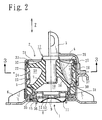
- the present invention relates to a fluid-sealed anti-vibration device which is used in an engine mounting and the like in which a cylindrical bushing and a cone-shaped mounting are integrally provided and dynamic characteristics are improved in a cylindrical bushing .
- a cone-shaped mounting is known in the prior art, in which a first connecting member secured to a vibration generating side, a second connecting member secured to a vibration receiving side, and a substantially cone-shaped elastic body section for connecting the first and second connecting members are provided.
- a fluid chamber is provided inside the elastic body section which forms a part of the elastic wall of the fluid chamber.
- the fluid chamber is divided into a main fluid chamber and a sub-fluid chamber by a partition member and a first orifice is provided for communicating with both fluid chambers.
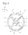
- a cylindrical bushing is also known in the prior art in which inner and outer tubes of a cylindrical shape are connected by an elastic member and a plurality of fluid chambers divided by the elastic member in the circumferential direction is provided. An orifice is arranged to communicate with these fluid chambers.
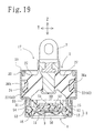
- the vertical direction (the front and rear direction when a car body is installed) and the lateral direction (the lateral direction when the car body is installed) in a condition shown by Fig. 1, and the vertical direction in Fig. 2 (the vertical direction when the car body is installed) are referred to as the X-axis direction, the Y-axis direction, and the Z-axis direction, respectively.
- the medium to high frequency bands here mean those between about 200 and 1,000 Hz.
- a fluid-sealed anti-vibration device which comprises a cone-shaped mounting section and a cylindrical bushing section, the cone-shaped mounting section being provided with a first connecting member secured to either of a vibration generating side or a vibration receiving side, a second connecting member secured to the other side, a substantially cone-shaped elastic body section for connecting the first and second connecting members, a fluid chamber of which part of an elastic wall is the elastic body section and of which the inside is divided into a main fluid chamber and a sub-fluid chamber by a partition member, and a first orifice for communicating with the main fluid chamber and the sub-fluid chamber, the cylindrical bushing section being provided with a plurality of side fluid chambers which are provided in the circumferential direction at predetermined intervals on the outer circumstance of the elastic body section and of which part of an elastic wall is the elastic body section, and a second orifice for communicating with each side fluid chamber, characterized
- Each natural membrane resonance in the cone-shaped mounting section and the cylindrical bushing section is a membrane resonance with the natural resonant frequency and the dynamic spring characteristics which can be obtained by filling and sealing a fluid in a fluid chamber on either side of the cone-shaped mounting section or the cylindrical bushing section, and by measuring the dynamic spring characteristics.
- the fluid-sealed anti-vibration device may be provided, wherein the cylindrical bushing section forms the maximum value of the dynamic spring constant in the natural frequency by a plurality of membrane resonances and also forms the minimum value of the dynamic spring constant on a higher frequency side than the natural frequency, while the cone-shaped mounting section generates a membrane resonance which forms the minimum value of the dynamic spring constant near and on a frequency side lower than the natural frequency which gives the maximum value.
- the fluid-sealed anti-vibration device may be provided, wherein the cylindrical bushing section forms the maximum value of the dynamic spring constant by the natural membrane resonance, and the cone-shaped mounting section also forms the minimum value of the dynamic spring constant by the natural membrane resonance, wherein there is the natural frequency where the minimum value on the mounting section side is formed near and on a frequency side higher than the natural frequency where the maximum value on the bushing section side is formed.
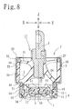
- an elastic membrane for absorbing the fluctuations in the internal pressure in the main fluid chamber may be provided, facing the main fluid chamber of the cone-shaped mounting section.
- a disc member adapted to move together with the first connecting member may be provided within the main fluid chamber of the cone-shaped mounting section.
- a second invention of a fluid-sealed anti-vibration device of this patent application comprises a first mounting member that is mounted on either a vibration generating side or a vibration receiving side, a second mounting member that is mounted on the other side and encloses the first mounting member in a nearly cylindrical state, an elastic partition wall provided for connecting these first and second mounting members and dividing the inside of the device into plural chambers, and a cylindrical bushing communicating with these fluid chambers through orifice passages, wherein three pairs of the fluid chambers are provided and three kinds of orifice passages are provided for communicating with each pair of fluid chambers through an orifice passage.
- liquid column resonance frequency of one of said three kinds of orifice passages having the largest rate of fluid flow out of three kinds of orifice passages can be set higher than the liquid column resonance frequencies of the other orifice passages.
- a fluid-sealed anti-vibration device having a cylindrical bushing section
- the cylindrical bushing section comprises a first connecting member secured to either of a vibration generating side or a vibration receiving side, a second connecting member secured to the other side and enclosing the periphery of the first connecting member in a substantially cylindrical shape, and an elastic partition wall for connecting the first and second connecting members, wherein the inside of the cylindrical bushing section is divided by the elastic partition wall into a plurality of fluid chambers, and an orifice is provided to communicate with each fluid chamber, characterized in that by press-fitting the elastic partition wall to the first or second connecting member side, the elastic partition wall is compressed by the first or second connecting member to adjust a spring ratio in the direction for connecting the first and second connecting members and in the direction substantially perpendicular to that direction.
- a fluid-sealed anti-vibration device having a cone-shaped mounting section and a cylindrical bushing section, in which the cone-shaped mounting section is provided with a first connecting member secured to either of a vibration generating side or a vibration receiving side, a second connecting member secured to the other side, and a substantially cone-shaped elastic body member for connecting the first and second connecting members, wherein a fluid chamber is provided of which part of an elastic wall is the elastic body member and of which the inside is divided by a partition member into a main fluid chamber and a sub-fluid chamber, and a first orifice is provided to communicate with the main fluid chamber and the sub-fluid chamber, and the cylindrical bushing section is provided with a plurality of side fluid chambers on the outer periphery of the elastic body member which is used in common with a part of the elastic wall of the fluid chambers, in the circumferential direction at a predetermined interval, wherein
- the fluid-sealed anti-vibration device according to the first or second invention can be provided, wherein a seat section to which the elastic partition wall is press-fitted is provided with a projecting section which engages a press-fitting end of the elastic partition wall, and there is provided a predetermined space between the projecting section and the elastic partition wall.
- the cylindrical bushing section is provided with a plurality of membrane resonant sections, wherein each forms the dynamic spring peak in the specified frequency and the dynamic spring bottom on the frequency side higher than the specified frequency. Accordingly, when the membrane resonance in the cone-shaped mounting section forms the dynamic spring bottom on the frequency side lower than the specified frequency in the dynamic spring peak, the dynamic spring peak on the cylindrical bushing section side is lowered. In this case, since the dynamic spring peak is generated on the frequency side lower than the dynamic spring bottom in the cylindrical bushing section, the low dynamic spring is realized in a wider range of frequencies.
- the spring value when there is provided a space between the press-fitting section of the elastic partition wall and the projecting section provided on the seat section, when the elastic partition wall is elastically deformed, the spring value is set to increase the amount of elastic deformation for smaller vibrations.
- the vibrations are large enough to allow the elastic partition wall to contact the projecting section, further elastic deformation is controlled to increase the spring value, wherein the spring value can be changed non-linearly.
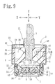
- Fig. 10 is an enlarged cross-sectional view (i.e. the cross-sectional view taken along line 10 - 10 of Fig. 9) of the engagement of the elastic partition wall 27 with the fluid chamber cover 22.
- Each connecting end section 41 of a pair of fluid chamber covers 22 is overlapped on the outer side of the end section 40 of the elastic partition wall 27.
- each fluid chamber cover 22 is provided with a projecting section 43 projecting from a seat section 42 to engage the end section 40 of the elastic partition wall 27.
- the inner surface 44 of the projecting section 43 is provided with a taper at an angle of ⁇ by which the space made between the elastic partition wall 27 and the inner surface 44 is gradually narrowed toward the outer direction.
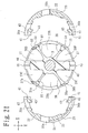
- the elastic main body portion 7, the end portion wall 21, the elastic partition wall 27, 37 and 38 comprising the cylindrical bushing portion 2 are all constructed continuously in one integral body using the same single elastic member. Further, these elastic materials are commonly used for the conical mounting portion 1 and therefore, the elastic material portion of the conical mounting portion 1, excepting the diaphragm 9 and the elastic material portions of the cylindrical bushing portion 2, are united in one integral body and become a single insert body 17 (Fig. 21), which can be treated as a single unit when assembling this engine mount.
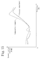
- the fourth orifice passage 36b is set so as to generate the dynamic spring bottom B9 by the liquid column resonance conforming to this dynamic spring peak P5
- the dynamic spring characteristic is generated by the fourth orifice passage 36b as shown by the virtual line, and, therefore, the actual dynamic spring characteristic will become a coupled one as shown by the solid line.
- the dynamic spring peak P5 drops to P6. Accordingly, the influence of the anti-resonance of the idle orifice passage is reduced and a low dynamic spring effect in a wide range of frequencies is realized.
- Fig. 25 is an example of tuning in which the damping orifice passage that is the second orifice passage 24 is coupled with other orifice passages.
- the damping characteristics are shown by the vertical axis showing the damping coefficient and the horizontal axis showing the frequency.
- a relatively acute angle peak is generated as shown by the broken lines.
- the third and fourth orifice passages 36a and 36b are set so that liquid column resonance is generated at a frequency slightly differing from the second orifice passage 24, the acute angle peak of each orifice passage is slightly shifted to the high frequency side and as a result, the coupled damping characteristic achieved becomes gentle as shown by the solid line. Accordingly, the broad range of damping which affects a wide range of frequencies can be realized.
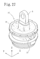
- Figs. 27 through 30 show the insert body 17, in which the end wall 21 is formed in a single disk shape.
- the fluid chamber cover 22 is first secured to the periphery of the insert body 45 and then inserted into the inside of the second connecting member 5 from the top in the figure.
- the partition wall 8 and the diaphragm 9 are inserted into the inside of the second connecting member 5 from the bottom (not shown), wherein the insert body is integrally provided by caulking the upper and lower sections of the second connecting member 5.
- cylindrical bushing section 2 can be selectively situated.
- the cross-sectional direction of the elastic partition wall 27 in Fig. 7 can be arranged toward the front and rear direction or the vertical direction of the car body. In this case, it is natural that the spring ratio be different from above.
- a cone-shaped mounting section is provided with the elastic partition walls extending radially in the front and rear direction and in the lateral direction and the elastic portion walls are compressed while assembling, thereby the spring ratio in the front and rear direction is controlled.
Landscapes
- Engineering & Computer Science (AREA)
- General Engineering & Computer Science (AREA)
- Mechanical Engineering (AREA)
- Combined Devices Of Dampers And Springs (AREA)
- Arrangement Or Mounting Of Propulsion Units For Vehicles (AREA)
Priority Applications (2)
| Application Number | Priority Date | Filing Date | Title |
|---|---|---|---|
| EP07022052A EP1887250B1 (fr) | 2001-04-10 | 2001-08-16 | Dispositif anti-vibration étanche aux fluides |
| EP07022051A EP1890052A1 (fr) | 2001-04-10 | 2001-08-16 | Dispositif anti-vibration étanche aux fluides |
Applications Claiming Priority (6)
| Application Number | Priority Date | Filing Date | Title |
|---|---|---|---|
| JP2001111870A JP4400809B2 (ja) | 2001-04-10 | 2001-04-10 | 液封防振装置 |
| JP2001111870 | 2001-04-10 | ||
| JP2001111869 | 2001-04-10 | ||
| JP2001111871A JP4447183B2 (ja) | 2001-04-10 | 2001-04-10 | 液封防振装置 |
| JP2001111869A JP4545343B2 (ja) | 2001-04-10 | 2001-04-10 | 液封防振装置 |
| JP2001111871 | 2001-04-10 |
Related Child Applications (2)
| Application Number | Title | Priority Date | Filing Date |
|---|---|---|---|
| EP07022052A Division EP1887250B1 (fr) | 2001-04-10 | 2001-08-16 | Dispositif anti-vibration étanche aux fluides |
| EP07022051A Division EP1890052A1 (fr) | 2001-04-10 | 2001-08-16 | Dispositif anti-vibration étanche aux fluides |
Publications (3)
| Publication Number | Publication Date |
|---|---|
| EP1249634A2 true EP1249634A2 (fr) | 2002-10-16 |
| EP1249634A3 EP1249634A3 (fr) | 2005-02-16 |
| EP1249634B1 EP1249634B1 (fr) | 2008-01-02 |
Family
ID=27346508
Family Applications (3)
| Application Number | Title | Priority Date | Filing Date |
|---|---|---|---|
| EP07022052A Expired - Lifetime EP1887250B1 (fr) | 2001-04-10 | 2001-08-16 | Dispositif anti-vibration étanche aux fluides |
| EP01119863A Expired - Lifetime EP1249634B1 (fr) | 2001-04-10 | 2001-08-16 | Dispositif anti-vibratoire renfermant du liquide |
| EP07022051A Withdrawn EP1890052A1 (fr) | 2001-04-10 | 2001-08-16 | Dispositif anti-vibration étanche aux fluides |
Family Applications Before (1)
| Application Number | Title | Priority Date | Filing Date |
|---|---|---|---|
| EP07022052A Expired - Lifetime EP1887250B1 (fr) | 2001-04-10 | 2001-08-16 | Dispositif anti-vibration étanche aux fluides |
Family Applications After (1)
| Application Number | Title | Priority Date | Filing Date |
|---|---|---|---|
| EP07022051A Withdrawn EP1890052A1 (fr) | 2001-04-10 | 2001-08-16 | Dispositif anti-vibration étanche aux fluides |
Country Status (4)
| Country | Link |
|---|---|
| US (1) | US6820867B2 (fr) |
| EP (3) | EP1887250B1 (fr) |
| DE (1) | DE60132168T2 (fr) |
| ES (1) | ES2295092T3 (fr) |
Families Citing this family (17)
| Publication number | Priority date | Publication date | Assignee | Title |
|---|---|---|---|---|
| JP3849534B2 (ja) * | 2002-01-29 | 2006-11-22 | 東海ゴム工業株式会社 | 流体封入式防振装置 |
| JP2005273906A (ja) * | 2004-02-27 | 2005-10-06 | Tokai Rubber Ind Ltd | 液体封入式防振装置 |
| US20080140921A1 (en) * | 2004-06-10 | 2008-06-12 | Sehat Sutardja | Externally removable non-volatile semiconductor memory module for hard disk drives |
| US7730335B2 (en) * | 2004-06-10 | 2010-06-01 | Marvell World Trade Ltd. | Low power computer with main and auxiliary processors |
| JP2006064033A (ja) * | 2004-08-25 | 2006-03-09 | Tokai Rubber Ind Ltd | 流体封入式防振装置 |
| JP4217686B2 (ja) * | 2004-09-29 | 2009-02-04 | 株式会社ブリヂストン | 防振装置 |
| CN101460762B (zh) * | 2006-04-07 | 2010-09-08 | 株式会社普利司通 | 减振装置 |
| JP4803605B2 (ja) * | 2007-03-22 | 2011-10-26 | 本田技研工業株式会社 | 液封防振装置 |
| JP2012202512A (ja) * | 2011-03-28 | 2012-10-22 | Tokai Rubber Ind Ltd | 多方向防振型の流体封入式防振装置 |
| DE102011102076B3 (de) * | 2011-05-19 | 2012-09-20 | Carl Freudenberg Kg | Hydrolager |
| JP5960542B2 (ja) * | 2012-08-07 | 2016-08-02 | 山下ゴム株式会社 | 液封ブッシュ |
| JP6297371B2 (ja) * | 2014-03-17 | 2018-03-20 | 住友理工株式会社 | 流体封入式防振装置の製造方法 |
| JP6757134B2 (ja) * | 2015-12-16 | 2020-09-16 | 山下ゴム株式会社 | 防振装置 |
| EP3589861B1 (fr) * | 2018-03-12 | 2024-05-01 | Vibracoustic SE | Membrane et palier à amortissement hydraulique |
| MY194967A (en) * | 2018-06-06 | 2022-12-28 | Univ Putra Malaysia | A viscoelastic bracing damper |
| JP7060531B2 (ja) * | 2019-02-15 | 2022-04-26 | 本田技研工業株式会社 | 液封ブッシュ |
| DE102024119100A1 (de) * | 2024-07-04 | 2026-01-08 | Vibracoustic Se | Hydraulisch dämpfendes Lager |
Citations (1)
| Publication number | Priority date | Publication date | Assignee | Title |
|---|---|---|---|---|
| EP0127986A2 (fr) | 1983-06-01 | 1984-12-12 | Industries Development Corporation (International Services) Ltd. | Système d'entraînement pour véhicule |
Family Cites Families (25)
| Publication number | Priority date | Publication date | Assignee | Title |
|---|---|---|---|---|
| DE2841505C2 (de) * | 1978-09-23 | 1983-04-07 | Boge Gmbh, 5208 Eitorf | Hydraulisch dämpfendes Gummilager |
| US4342446A (en) * | 1980-11-18 | 1982-08-03 | Gould Inc. | Self-leveling viscous elastic damper |
| DE3614161A1 (de) * | 1986-04-26 | 1987-11-05 | Lemfoerder Metallwaren Ag | Zweikammerstuetzlager mit hydraulischer daempfung, insbesondere motorlager in kraftfahrzeugen |
| DE3618767C2 (de) | 1986-06-04 | 1995-04-13 | Audi Ag | Motorlager mit hydraulischer Dämpfung |
| JPS63145837A (ja) * | 1986-07-04 | 1988-06-17 | Tokai Rubber Ind Ltd | 円筒型流体封入式防振支持体 |
| DE3632670A1 (de) * | 1986-09-26 | 1988-04-07 | Boge Ag | Hydraulisch daempfendes gummilager |
| US4842258A (en) * | 1987-04-17 | 1989-06-27 | Toyota Jidosha Kabushiki Kaisha | Composite engine mount |
| FR2625780B1 (fr) * | 1988-01-08 | 1992-04-10 | Gamma Sa | Amortisseur de vibrations perfectionne |
| DE3808630A1 (de) * | 1988-03-15 | 1989-10-05 | Metzeler Gmbh | Elastische und hydraulisch daempfende buchse |
| JPH0253543U (fr) * | 1988-10-08 | 1990-04-18 | ||
| JPH03121327A (ja) * | 1989-10-02 | 1991-05-23 | Tokai Rubber Ind Ltd | 流体封入式筒型マウント装置 |
| JPH03144134A (ja) * | 1989-10-31 | 1991-06-19 | Toyoda Gosei Co Ltd | 液封入防振装置 |
| FR2659712B1 (fr) * | 1990-03-16 | 1992-07-17 | Hutchinson | Perfectionnements apportes aux manchons antivibratoires hydrauliques. |
| DE4015523C1 (fr) * | 1990-05-15 | 1991-11-14 | Boge Ag, 5208 Eitorf, De | |
| FR2687202B1 (fr) * | 1992-02-10 | 1995-06-16 | Peugeot | Support hydroelastique. |
| JP3144134B2 (ja) | 1993-03-26 | 2001-03-12 | 日産自動車株式会社 | 背凭れ背面衝撃吸収装置 |
| US5657510A (en) * | 1995-06-14 | 1997-08-19 | Yamashita Rubber Kabushiki Kaisha | Fluid-filled insulating bushing |
| JPH0942367A (ja) * | 1995-07-28 | 1997-02-10 | Bridgestone Corp | 防振装置 |
| JP3748625B2 (ja) * | 1996-06-18 | 2006-02-22 | 本田技研工業株式会社 | 液体封入ブッシュ |
| US5927698A (en) * | 1996-07-24 | 1999-07-27 | Toyoda Gosei Co., Ltd. | Liquid sealed-type vibration insulating device |
| JP3487123B2 (ja) * | 1997-03-18 | 2004-01-13 | 東海ゴム工業株式会社 | 流体封入式防振装置 |
| JP4179704B2 (ja) * | 1999-05-14 | 2008-11-12 | 山下ゴム株式会社 | 液封防振装置 |
| JP4275810B2 (ja) | 1999-07-02 | 2009-06-10 | 山下ゴム株式会社 | 液封防振装置 |
| EP1111267B1 (fr) * | 1999-12-24 | 2004-09-22 | Yamashita Rubber Kabushiki Kaisha | Dispositif antivibratoire renfermant un fluide |
| DE60021052T2 (de) * | 1999-12-28 | 2005-12-22 | Yamashita Rubber K.K. | Flüssigkeitsenthaltende und Schwingungsdämpfende Vorrichtung |
-
2001
- 2001-08-16 EP EP07022052A patent/EP1887250B1/fr not_active Expired - Lifetime
- 2001-08-16 US US09/930,296 patent/US6820867B2/en not_active Expired - Fee Related
- 2001-08-16 ES ES01119863T patent/ES2295092T3/es not_active Expired - Lifetime
- 2001-08-16 DE DE60132168T patent/DE60132168T2/de not_active Expired - Lifetime
- 2001-08-16 EP EP01119863A patent/EP1249634B1/fr not_active Expired - Lifetime
- 2001-08-16 EP EP07022051A patent/EP1890052A1/fr not_active Withdrawn
Patent Citations (1)
| Publication number | Priority date | Publication date | Assignee | Title |
|---|---|---|---|---|
| EP0127986A2 (fr) | 1983-06-01 | 1984-12-12 | Industries Development Corporation (International Services) Ltd. | Système d'entraînement pour véhicule |
Also Published As
| Publication number | Publication date |
|---|---|
| EP1887250A1 (fr) | 2008-02-13 |
| EP1887250B1 (fr) | 2012-01-11 |
| US20020145240A1 (en) | 2002-10-10 |
| EP1249634B1 (fr) | 2008-01-02 |
| EP1890052A1 (fr) | 2008-02-20 |
| EP1249634A3 (fr) | 2005-02-16 |
| ES2295092T3 (es) | 2008-04-16 |
| US6820867B2 (en) | 2004-11-23 |
| DE60132168T2 (de) | 2008-05-08 |
| DE60132168D1 (de) | 2008-02-14 |
Similar Documents
| Publication | Publication Date | Title |
|---|---|---|
| EP1887250B1 (fr) | Dispositif anti-vibration étanche aux fluides | |
| EP1113187B1 (fr) | Dispositif anti-vibratoire renfermant du liquide | |
| US4630808A (en) | Vibration isolating devices | |
| US5183243A (en) | Fluid-filled elastic mount having caulked portion for sealing off fluid chamber | |
| US8177201B2 (en) | Very high damping mount with bolt-through construction | |
| US8282086B2 (en) | Vibration isolator | |
| JP2005273684A (ja) | 流体封入式防振装置 | |
| US8231115B2 (en) | Very high damping body mount, subframe mount or engine mount with bolt-through construction | |
| US6557839B2 (en) | Fluid-filled vibration damping device and method of producing the same | |
| JP2000193015A (ja) | 流体封入式防振装置 | |
| JP2007521444A (ja) | エンジンマウント | |
| CN101460761B (zh) | 防振装置 | |
| JP4400809B2 (ja) | 液封防振装置 | |
| JP4716615B2 (ja) | 液封防振装置 | |
| JP4545343B2 (ja) | 液封防振装置 | |
| JPH10132016A (ja) | 液体封入式防振マウント | |
| JPH06221372A (ja) | 流体封入式筒型マウント装置 | |
| JP4231980B2 (ja) | 液体封入式マウント | |
| JP5108704B2 (ja) | 流体封入式エンジンマウント | |
| JP4162456B2 (ja) | 液体封入型防振装置 | |
| JP2008240890A (ja) | 流体封入式防振装置 | |
| JPH07180743A (ja) | 流体封入式マウント | |
| JP2008163975A (ja) | 流体封入式防振装置 | |
| JP2025003192A (ja) | 吊下型の流体封入式防振装置 | |
| JP2007255442A (ja) | 流体封入式防振装置 |
Legal Events
| Date | Code | Title | Description |
|---|---|---|---|
| PUAI | Public reference made under article 153(3) epc to a published international application that has entered the european phase |
Free format text: ORIGINAL CODE: 0009012 |
|
| AK | Designated contracting states |
Kind code of ref document: A2 Designated state(s): AT BE CH CY DE DK ES FI FR GB GR IE IT LI LU MC NL PT SE TR |
|
| AX | Request for extension of the european patent |
Free format text: AL;LT;LV;MK;RO;SI |
|
| PUAL | Search report despatched |
Free format text: ORIGINAL CODE: 0009013 |
|
| RIC1 | Information provided on ipc code assigned before grant |
Ipc: 7F 16F 13/10 B Ipc: 7F 16F 13/14 B Ipc: 7F 16F 13/16 A |
|
| AK | Designated contracting states |
Kind code of ref document: A3 Designated state(s): AT BE CH CY DE DK ES FI FR GB GR IE IT LI LU MC NL PT SE TR |
|
| AX | Request for extension of the european patent |
Extension state: AL LT LV MK RO SI |
|
| 17P | Request for examination filed |
Effective date: 20050517 |
|
| 17Q | First examination report despatched |
Effective date: 20050613 |
|
| AKX | Designation fees paid |
Designated state(s): DE ES FR GB IT |
|
| GRAP | Despatch of communication of intention to grant a patent |
Free format text: ORIGINAL CODE: EPIDOSNIGR1 |
|
| GRAS | Grant fee paid |
Free format text: ORIGINAL CODE: EPIDOSNIGR3 |
|
| GRAA | (expected) grant |
Free format text: ORIGINAL CODE: 0009210 |
|
| AK | Designated contracting states |
Kind code of ref document: B1 Designated state(s): DE ES FR GB IT |
|
| REG | Reference to a national code |
Ref country code: GB Ref legal event code: FG4D |
|
| REF | Corresponds to: |
Ref document number: 60132168 Country of ref document: DE Date of ref document: 20080214 Kind code of ref document: P |
|
| REG | Reference to a national code |
Ref country code: ES Ref legal event code: FG2A Ref document number: 2295092 Country of ref document: ES Kind code of ref document: T3 |
|
| PGFP | Annual fee paid to national office [announced via postgrant information from national office to epo] |
Ref country code: ES Payment date: 20080828 Year of fee payment: 8 |
|
| PLBE | No opposition filed within time limit |
Free format text: ORIGINAL CODE: 0009261 |
|
| STAA | Information on the status of an ep patent application or granted ep patent |
Free format text: STATUS: NO OPPOSITION FILED WITHIN TIME LIMIT |
|
| PGFP | Annual fee paid to national office [announced via postgrant information from national office to epo] |
Ref country code: IT Payment date: 20080823 Year of fee payment: 8 |
|
| 26N | No opposition filed |
Effective date: 20081003 |
|
| PGFP | Annual fee paid to national office [announced via postgrant information from national office to epo] |
Ref country code: GB Payment date: 20080821 Year of fee payment: 8 |
|
| GBPC | Gb: european patent ceased through non-payment of renewal fee |
Effective date: 20090816 |
|
| REG | Reference to a national code |
Ref country code: ES Ref legal event code: FD2A Effective date: 20090817 |
|
| PG25 | Lapsed in a contracting state [announced via postgrant information from national office to epo] |
Ref country code: GB Free format text: LAPSE BECAUSE OF NON-PAYMENT OF DUE FEES Effective date: 20090816 |
|
| PG25 | Lapsed in a contracting state [announced via postgrant information from national office to epo] |
Ref country code: IT Free format text: LAPSE BECAUSE OF NON-PAYMENT OF DUE FEES Effective date: 20090816 |
|
| PG25 | Lapsed in a contracting state [announced via postgrant information from national office to epo] |
Ref country code: ES Free format text: LAPSE BECAUSE OF NON-PAYMENT OF DUE FEES Effective date: 20090817 |
|
| PGFP | Annual fee paid to national office [announced via postgrant information from national office to epo] |
Ref country code: FR Payment date: 20110901 Year of fee payment: 11 |
|
| REG | Reference to a national code |
Ref country code: FR Ref legal event code: ST Effective date: 20130430 |
|
| PG25 | Lapsed in a contracting state [announced via postgrant information from national office to epo] |
Ref country code: FR Free format text: LAPSE BECAUSE OF NON-PAYMENT OF DUE FEES Effective date: 20120831 |
|
| PGFP | Annual fee paid to national office [announced via postgrant information from national office to epo] |
Ref country code: DE Payment date: 20150811 Year of fee payment: 15 |
|
| REG | Reference to a national code |
Ref country code: DE Ref legal event code: R119 Ref document number: 60132168 Country of ref document: DE |
|
| PG25 | Lapsed in a contracting state [announced via postgrant information from national office to epo] |
Ref country code: DE Free format text: LAPSE BECAUSE OF NON-PAYMENT OF DUE FEES Effective date: 20170301 |