EP1251034A2 - Lösemechanismus und dessen Verwendung in einem Datenaufzeichnungs- Wiedergabegerät - Google Patents
Lösemechanismus und dessen Verwendung in einem Datenaufzeichnungs- Wiedergabegerät Download PDFInfo
- Publication number
- EP1251034A2 EP1251034A2 EP02252739A EP02252739A EP1251034A2 EP 1251034 A2 EP1251034 A2 EP 1251034A2 EP 02252739 A EP02252739 A EP 02252739A EP 02252739 A EP02252739 A EP 02252739A EP 1251034 A2 EP1251034 A2 EP 1251034A2
- Authority
- EP
- European Patent Office
- Prior art keywords
- operating panel
- detaching
- detachable member
- grill
- operating
- Prior art date
- Legal status (The legal status is an assumption and is not a legal conclusion. Google has not performed a legal analysis and makes no representation as to the accuracy of the status listed.)
- Granted
Links
Images



Classifications
-
- H—ELECTRICITY
- H04—ELECTRIC COMMUNICATION TECHNIQUE
- H04B—TRANSMISSION
- H04B1/00—Details of transmission systems, not covered by a single one of groups H04B3/00 - H04B13/00; Details of transmission systems not characterised by the medium used for transmission
- H04B1/38—Transceivers, i.e. devices in which transmitter and receiver form a structural unit and in which at least one part is used for functions of transmitting and receiving
- H04B1/3822—Transceivers, i.e. devices in which transmitter and receiver form a structural unit and in which at least one part is used for functions of transmitting and receiving specially adapted for use in vehicles
-
- B—PERFORMING OPERATIONS; TRANSPORTING
- B60—VEHICLES IN GENERAL
- B60R—VEHICLES, VEHICLE FITTINGS, OR VEHICLE PARTS, NOT OTHERWISE PROVIDED FOR
- B60R11/00—Arrangements for holding or mounting articles, not otherwise provided for
- B60R11/02—Arrangements for holding or mounting articles, not otherwise provided for for radio sets, television sets, telephones, or the like; Arrangement of controls thereof
-
- E—FIXED CONSTRUCTIONS
- E05—LOCKS; KEYS; WINDOW OR DOOR FITTINGS; SAFES
- E05D—HINGES OR SUSPENSION DEVICES FOR DOORS, WINDOWS OR WINGS
- E05D1/00—Pinless hinges; Substitutes for hinges
-
- G—PHYSICS
- G11—INFORMATION STORAGE
- G11B—INFORMATION STORAGE BASED ON RELATIVE MOVEMENT BETWEEN RECORD CARRIER AND TRANSDUCER
- G11B33/00—Constructional parts, details or accessories not provided for in the other groups of this subclass
- G11B33/02—Cabinets; Cases; Stands; Disposition of apparatus therein or thereon
-
- H—ELECTRICITY
- H04—ELECTRIC COMMUNICATION TECHNIQUE
- H04B—TRANSMISSION
- H04B1/00—Details of transmission systems, not covered by a single one of groups H04B3/00 - H04B13/00; Details of transmission systems not characterised by the medium used for transmission
- H04B1/06—Receivers
- H04B1/08—Constructional details, e.g. cabinet
Definitions
- the present invention relates to a detaching mechanism and an information recording and reproducing apparatus using the detaching mechanism, and more particularly to a theft-prevention structure in a vehicle-mounted information recording and reproducing apparatus.
- CD Compact Disc
- DVD Digital Versatile Disc
- MD Mini Disc
- the vehicle-mounted information recording and reproducing apparatus Since the vehicle-mounted information recording and reproducing apparatus is relatively expensive and has a small structure, the apparatus can be detached even in the case of being mounted in the vehicle, so that there is a great risk of suffering theft.
- a structure for theft prevention there is a structure constructed so that the circumference of an operating panel is fixed by a frame member which is a member separate from the information reproducing apparatus and the frame member can be detached by a special tool, or a structure in which the whole surface of an operating panel is coated with a cover capable of being integrated with an instrument panel in which this operating panel is mounted.
- This structure has an effect of recognizing that theft is useless by being constructed so as to be able to decide that the information recording and reproducing apparatus cannot be operated easily from the outside by detaching the operating panel from the information recording and reproducing apparatus and keeping its state.
- an object of the invention is to provide a detaching mechanism having a structure capable of surely preventing careless dropping at the time of attachment and detachment to prevent damage to a separable operating panel while improving attachment and detachment operability, and an information recording and reproducing apparatus using this mechanism.
- a detaching mechanism targeted for an operating panel including operating switches and the like, in which only a part of the operating panel can set a forward-bent posture and a separation posture at the time when a part of the operating panel is disengaged from a support surface of this operating panel.
- the forward-bent posture can be set at the time of attachment or detachment, so that careless dropping does not occur.
- separation can be performed in this state, so that a part of the operating panel stopping in the forward-bent posture can be pulled out and detached from the support surface .
- a part of the operating panel is openably supported by a hinge part and the hinge part can be mounted in a rod-shaped hinge receiving part located in a part of the support surface of the operating panel to be opened or closed and engaged or disengaged.
- the hinge part mounted with respect to the hinge receiving part of the side of the support surface is provided in a part of the operating panel, so that a part of the operating panel can be detached easily by releasing a mounted state of the hinge part in the hinge receiving part.
- the operating panel is openably provided, and both the lateral edges corresponding to a direction perpendicular to the opening and closing direction are formed in slope surfaces continuous with the support surface, and the slope surfaces are formed in taper surfaces which become narrower toward the side of an opening and closing support position in the operating panel.
- both the lateral edges in a part of the operating panel are formed in the slope surfaces continuous with the support surface and this slope surface is formed in the taper surface which becomes narrower toward the side of the opening and closing support in a part of the operating panel, so that when a part of the operating panel is opened, both the lateral edges interfere with slope surfaces of the side of the support surface and an opening operation of a part of the operating panel is regulated. As a result of this, the opening operation is stopped halfway and the forward-bent posture is maintained and careless dropping can be prevented.
- a part of the operating panel an engagement stop part capable of engaging or disengaging with respect to the support surface is provided in a position opposite to the opening and closing support part, and a part of the slope surface abuts on a part of a slope surface of the side of the support surface during opening at the time when the engagement stop part is disengaged and thereby a forward-bent posture can be maintained.
- both the lateral edges canbe abutted on the slope surfaces of the side of the support surface to maintain the forward-bent posture, so that a part of the operating panel does not drop from the support surface while releasing an engagement state.
- an information recording and reproducing apparatus uses the above mechanism.
- only a part of the operating panel in the information recording and reproducing apparatus can be opened or closed with respect to the support surface which is the other part and also the forward-bent posture can be maintained during opening or closing.
- Fig. 1 is an external view of an information recording and reproducing apparatus using a detaching mechanism according to an embodiment of the invention.
- the information recording and reproducing apparatus shown in Fig. 1 is an apparatus for reproducing information made from a storage medium such as CD (Compact Disc), DVD (Digital Versatile Disc) or MD (Mini Disc) , and the embodiment is targeted for a vehicle-mounted car audio apparatus (hereinafter called a vehicle-mounted information recording and reproducing apparatus).
- a vehicle-mounted information recording and reproducing apparatus hereinafter called a vehicle-mounted information recording and reproducing apparatus.
- the vehicle-mounted information recording and reproducing apparatus 1 comprises an apparatus body 2 in which an operating panel 2B equipped with a slot-in opening 2A capable of inserting a record medium and various operating switches and the like is provided in the front, and a display panel 3 equipped with a liquid crystal panel in the front.
- the apparatus body 2 is provided with a reproducing apparatus of the record medium (not shown), and it is constructed so that setting of reproducing conditions or pullout of the record medium can be performed according to operations of the operating switches and the like with which the operating panel 2B is equipped.
- the display panel 3 is constructed so that a screen structure acting as a monitor can be obtained by pulling out a part of the display panel to the front and raising it (not shown).
- the operating panel 2B is equipped with a detaching grill 4 in which a part of the operating panel 2B can be separated from the other part, and in the detaching grill 4, push buttons (for the sake of convenience, shown by numeral P in Fig. 1) capable of operating the various switches and the like provided in the operating panel 2B are provided in parallel.
- Fig. 2 it is constructed so that a part of the push button P protrudes to the rear of the detaching grill 4 and the protruding portion can be opposed to the switch and the like (for the sake of convenience, shown by numeral S in Fig. 2) provided in the side of the operating panel 2B to be interlocked.
- the detaching mechanism capable of setting attachment and detachment postures of the detaching grill 4 includes a structure in which the detaching grill 4 can be held in a forward-bent posture at the time of disengaging an engagement state with respect to the operating panel 2B while detachably supporting the detaching grill 4, and its structure includes hinge receiving parts 5 and an engagement stop part 6 provided in the side of the operating panel 2B, and hinge parts 7 and an engagement part 8 provided in the side of the detaching grill 4 as shown in Fig.2.
- a recess part 2B1 for forming support space capable of holding the detaching grill 4 is provided in the side of the operating panel 2B, and rod-shaped hinge receiving parts 5 which are one of members forming the detaching mechanism in the side of the operating panel 2B are provided in the lower portions of both sides in the recess part 2B1, and a hook-shaped engagement stop part 6 which is one of the members forming the detaching mechanism in the side of the operating panel 2B similarly is provided in the upper portion of the lateral center of the recess part 2B1.
- recess-shaped hinge parts 7 having downward openings which are one of the members forming the detaching mechanism in the side of the detaching grill 4 by integral molding in the lower portions of both the lateral sides of the detaching grill 4 can be mounted and supported suitably with respect to the hinge receiving parts 5.
- the detaching grill 4 is supported openably with respect to the recess part 2B1 of the operating panel 2B which becomes a support surface of the detaching grill 4 using the hinge receiving parts 5 as a fulcrum and also is detached from the operating panel 2B by pulling the hinge parts 7 from the hinge receiving parts 5.
- an engagement member 8 which is one of the members forming the detaching mechanism provided opposite to this engagement stop part 6 in the side of the detaching grill 4 can be engaged and disengaged with respect to an engagement stop part 6 provided in the upper portion of the lateral center of the recess part 2B1.
- the engagement member 8 is provided retractably with respect to the engagement stop part 6 using an elastic body such as a spring (not shown) and is disengaged from the engagement stop part 6 by pushing and operating a part of the detaching grill 4 exposed to the front.
- Fig. 3 is an arrow view of a direction shown by numeral (3) in Fig. 1, and an opening and closing state of the detaching grill 4 is shown in Fig. 3.
- both the lateral edges corresponding to a direction perpendicular to an opening and closing direction are constructed by slope surfaces 4A continuous with support surfaces of the recess part 2B1 in the operating panel 2B, namely opening edges 2C of the recess part 2B1, and this slope surface 4A is formed in a taper surface which becomes narrower toward the side of an opening and closing support position of the operating panel 2B, namely the hinge receiving parts 5.
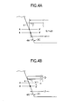
- the slope surfaces 4Aof the detaching grill 4 are provided in order to set a forward-bent posture at the time of opening the detaching grill 4, and its principle is shown in Figs. 4A and 4B.
- Figs. 4A and 4B show an opposite relation between an arbitrary position of the side of the detaching grill 4 and a position of the opening edges of the recess part 2B1 opposite to this detaching grill 4, and Fig. 4A shows a state in which the detaching grill 4 is closed and held within the recess part 2B1, and Fig. 4B shows a process of opening the detaching grill 4.
- the slope surface 4A has a length in which an arbitrary position (position shown by numeral A') of the opening end side with respect to a slope surface 2C of the opening edge interferes with the slope surface 2C of the opening edge side by opening of the detaching grill 4.
- it is constructed so as to stop further opening since the arbitrary position A' of the side of the detaching grill 4 interferes and abuts with the slope surface 2C of the opening edge when the arbitrary position A' of the side of the detaching grill 4 in a position relation shown by numerals A and A' in Fig. 4A is opposed to a position (position shown by numeral B in Fig.
- Fig. 5 is an external view of a state shown in Fig. 4B, and in the detaching grill 4, both the edges of the opening edge side abut on the slope surfaces of the opening edge side during opening and the opening is stopped.
- An opening angle of the detaching grill 4 shown in Fig. 5 is set to an angle capable of pulling the hinge parts 7 of the detaching grill 4 from the hinge receiving parts 5 (see Figs. 2 and 3).
- the hinge parts 7 of the detaching grill 4 separated from the operating panel 2B are fitted into the hinge receiving parts 5 of the side of the recess part 2B1 and are rotated in a closing direction using the hinge receiving parts 5 as a fulcrum.
- the engagement member 8 of the side of the detaching grill 4 interferes with the engagement stop part 6 of the side of the recess part 2B1 and is pushed down by the engagement stop part 6 against the own energization force and when the engagement member 8 gets over the engagement stop part 6, the engagement member 8 engages with the engagement stop part 6 by the own energization force.
- a state in which the detaching grill 4 is held within the recess part 2B1 can be maintained.
- the detaching grill 4 is detached from the operating panel 2B.
- the switches on the operating panels cannot be operated at the side of the information recording and reproducing apparatus in the state that the detaching grill 4 is completely detached from the operating panel 2B. This structure contributes to preventing the information recording and reproducing apparatus from being stolen.
- the engagement member 8 which is a component member of the detaching mechanism in the side of the detaching grill 4 is disengaged from the engagement stop part 6 which is a component member of the detaching mechanism in the side of the operating panel 2B and the detaching grill 4 is rotated in an opening direction.
- the slope surface 4A interferes and abuts with the slope surface 2C of the opening edge of the recess part 2B1 as shown in Figs. 4A and 4B in a process of rotating the detaching grill 4 in an opening direction, so that the rotation is stopped against the moment by the own weight.
- the rotation is automatically stopped and a forward-bent posture is maintained and the rotation is not performed until dropping, so that the detaching grill 4 can be prevented from dropping carelessly from the recess part 2B1.
- damage to the side of the detaching grill 4 occurring in the case that the detaching grill 4 has dropped carelessly can be prevented.
- the detaching grill 4 stopping in the forward-bent posture is detached from the recess part 2B1 of the operating panel 2B by grasping the hinge parts 7 from the hinge receiving parts 5 in a pullout direction and releasing amounting state.
- a situation in which the detaching grill 4 forming a part of the operating panel 2B drops carelessly can be prevented, so that the detaching grill 4 can be downsized. Because of this, the operating switches and the like of the side of the operating panel 2B capable of operation by the detaching grill 4 can be downsized, so that circumstances difficult to operate the switches and the like by fingers can be formed even if the detaching grill 4 is detached. As a result of this, the degree of difficulty of operation in the operating panel 2B capable of observation from the outside with the detaching grill 4 detached can be recognized easily.
- a part of an operating panel can be detached from the other support surface, so that a detached component can be downsized as compared with the case of detaching the whole operating panel.
- a theft-prevention structure of an information recording and reproducing apparatus can be obtained in a state in which inconvenience of conveyance is improved.
- a forward-bent posture can be maintained in an opening process as well as attachment and detachment postures when a part of the operating panel is detached, so that damage to a component targeted for detaching can be prevented by preventing careless dropping.
Landscapes
- Engineering & Computer Science (AREA)
- Computer Networks & Wireless Communication (AREA)
- Signal Processing (AREA)
- Mechanical Engineering (AREA)
- Casings For Electric Apparatus (AREA)
- Fittings On The Vehicle Exterior For Carrying Loads, And Devices For Holding Or Mounting Articles (AREA)
Applications Claiming Priority (2)
| Application Number | Priority Date | Filing Date | Title |
|---|---|---|---|
| JP2001123179A JP4346831B2 (ja) | 2001-04-20 | 2001-04-20 | デタッチ機構およびこれを用いた情報記録再生装置 |
| JP2001123179 | 2001-04-20 |
Publications (3)
| Publication Number | Publication Date |
|---|---|
| EP1251034A2 true EP1251034A2 (de) | 2002-10-23 |
| EP1251034A3 EP1251034A3 (de) | 2003-08-20 |
| EP1251034B1 EP1251034B1 (de) | 2007-05-30 |
Family
ID=18972778
Family Applications (1)
| Application Number | Title | Priority Date | Filing Date |
|---|---|---|---|
| EP02252739A Expired - Lifetime EP1251034B1 (de) | 2001-04-20 | 2002-04-18 | Lösemechanismus und dessen Verwendung in einem Datenaufzeichnungs- Wiedergabegerät |
Country Status (4)
| Country | Link |
|---|---|
| US (1) | US20020152579A1 (de) |
| EP (1) | EP1251034B1 (de) |
| JP (1) | JP4346831B2 (de) |
| DE (1) | DE60220331T2 (de) |
Cited By (10)
| Publication number | Priority date | Publication date | Assignee | Title |
|---|---|---|---|---|
| EP1931040A2 (de) | 2006-12-04 | 2008-06-11 | Fujitsu Ten Limited | Elektronische Vorrichtung und elektronisches System |
| US7638896B2 (en) | 2006-12-04 | 2009-12-29 | Fujitsu Ten Limited | In-vehicle electronic system, in-vehicle electronic apparatus and method of controlling power supply of portable electronic device |
| US7684200B2 (en) | 2006-12-28 | 2010-03-23 | Fujitsu Ten Limited | Electronic apparatus and electronic system |
| US7739009B2 (en) | 2006-12-04 | 2010-06-15 | Fujitsu Ten Limited | In-vehicle electronic system and in-vehicle electronic apparatus |
| US7765046B2 (en) | 2006-12-28 | 2010-07-27 | Fujitsu Ten Limited | In-vehicle electronic apparatus and in-vehicle electronic system |
| US7774104B2 (en) | 2006-12-27 | 2010-08-10 | Fujitsu Ten Limited | Electronic apparatus and electronic system |
| US7860643B2 (en) | 2006-12-28 | 2010-12-28 | Fujitsu Ten Limited | In-vehicle detachably electronic apparatus and in-vehicle electronic system |
| US7869196B2 (en) | 2006-12-28 | 2011-01-11 | Fujitsu Ten Limited | Electronic apparatus |
| US7904236B2 (en) | 2006-12-28 | 2011-03-08 | Fujitsu Ten Limited | Electronic apparatus and electronic system |
| US8706396B2 (en) | 2006-12-28 | 2014-04-22 | Fujitsu Ten Limited | Electronic apparatus and electronic system |
Families Citing this family (3)
| Publication number | Priority date | Publication date | Assignee | Title |
|---|---|---|---|---|
| JP4732768B2 (ja) * | 2005-02-18 | 2011-07-27 | 能美防災株式会社 | 消火栓装置 |
| JP5090035B2 (ja) * | 2007-03-22 | 2012-12-05 | パナソニック株式会社 | 車載電子機器 |
| JP2021062663A (ja) * | 2019-10-10 | 2021-04-22 | パイオニア株式会社 | 端末装置及び車載システム |
Family Cites Families (18)
| Publication number | Priority date | Publication date | Assignee | Title |
|---|---|---|---|---|
| US3902628A (en) * | 1972-09-13 | 1975-09-02 | Plastic Forming Company Inc | Plastic container hinge and latch |
| CH677244A5 (de) * | 1988-07-05 | 1991-04-30 | Von Roll Ag | |
| US4940414A (en) * | 1988-09-20 | 1990-07-10 | Namsung Electronics Corp. | Antitheft car audio set with removable control box |
| JP2934463B2 (ja) * | 1989-11-09 | 1999-08-16 | ホシデン株式会社 | 操作部着脱装置 |
| JPH0438899A (ja) * | 1990-06-05 | 1992-02-10 | Pioneer Electron Corp | 車載用音響機器のパネル着脱装置 |
| US5216904A (en) * | 1990-11-06 | 1993-06-08 | Pioneer Electronic Corporation | Handle device having a lock mechanism for an audio equipment |
| JPH04119746U (ja) * | 1991-04-12 | 1992-10-27 | パイオニア株式会社 | 電子部品操作装置 |
| JP2547924Y2 (ja) * | 1991-05-16 | 1997-09-17 | パイオニア株式会社 | カーステレオ装置 |
| US5449228A (en) * | 1991-12-27 | 1995-09-12 | Clarion Co., Ltd. | Apparatus for locking an operating unit to a vehicle-mounted electronic equipment |
| US5575544A (en) * | 1992-08-26 | 1996-11-19 | Clarion Co., Ltd. | Vehicle-mounted equipment anti-theft mechanism |
| EP0647546B1 (de) * | 1993-04-30 | 2000-07-26 | Shintom Co., Ltd | In einem fahrzeug montiertes audiogerät |
| US5852594A (en) * | 1995-12-29 | 1998-12-22 | Sony Corporation | Electronic equipment and recording and/or reproducing apparatus for recording medium |
| JPH09321449A (ja) * | 1996-05-27 | 1997-12-12 | Clarion Co Ltd | 記録媒体再生装置 |
| JP3563914B2 (ja) * | 1997-03-26 | 2004-09-08 | 富士通株式会社 | ホルダ装置 |
| KR100242773B1 (ko) * | 1997-06-07 | 2000-02-01 | 전주범 | 카 오디오용 컨트롤 패널의 결합구조 |
| US5815379A (en) * | 1997-06-09 | 1998-09-29 | Compaq Computer Corporation | Pivotable computer access door structure having concealed, break-away hinge mechanism |
| GB2336489A (en) * | 1998-04-14 | 1999-10-20 | Ford Motor Co | Latch for removable front portion of vehicle cassette radio |
| JP3986869B2 (ja) * | 2002-04-11 | 2007-10-03 | パイオニア株式会社 | 電子機器 |
-
2001
- 2001-04-20 JP JP2001123179A patent/JP4346831B2/ja not_active Expired - Fee Related
-
2002
- 2002-04-18 EP EP02252739A patent/EP1251034B1/de not_active Expired - Lifetime
- 2002-04-18 DE DE60220331T patent/DE60220331T2/de not_active Expired - Fee Related
- 2002-04-19 US US10/125,340 patent/US20020152579A1/en not_active Abandoned
Cited By (11)
| Publication number | Priority date | Publication date | Assignee | Title |
|---|---|---|---|---|
| EP1931040A2 (de) | 2006-12-04 | 2008-06-11 | Fujitsu Ten Limited | Elektronische Vorrichtung und elektronisches System |
| EP1931040A3 (de) * | 2006-12-04 | 2008-12-10 | Fujitsu Ten Limited | Elektronische Vorrichtung und elektronisches System |
| US7638896B2 (en) | 2006-12-04 | 2009-12-29 | Fujitsu Ten Limited | In-vehicle electronic system, in-vehicle electronic apparatus and method of controlling power supply of portable electronic device |
| US7739009B2 (en) | 2006-12-04 | 2010-06-15 | Fujitsu Ten Limited | In-vehicle electronic system and in-vehicle electronic apparatus |
| US7774104B2 (en) | 2006-12-27 | 2010-08-10 | Fujitsu Ten Limited | Electronic apparatus and electronic system |
| US7684200B2 (en) | 2006-12-28 | 2010-03-23 | Fujitsu Ten Limited | Electronic apparatus and electronic system |
| US7765046B2 (en) | 2006-12-28 | 2010-07-27 | Fujitsu Ten Limited | In-vehicle electronic apparatus and in-vehicle electronic system |
| US7860643B2 (en) | 2006-12-28 | 2010-12-28 | Fujitsu Ten Limited | In-vehicle detachably electronic apparatus and in-vehicle electronic system |
| US7869196B2 (en) | 2006-12-28 | 2011-01-11 | Fujitsu Ten Limited | Electronic apparatus |
| US7904236B2 (en) | 2006-12-28 | 2011-03-08 | Fujitsu Ten Limited | Electronic apparatus and electronic system |
| US8706396B2 (en) | 2006-12-28 | 2014-04-22 | Fujitsu Ten Limited | Electronic apparatus and electronic system |
Also Published As
| Publication number | Publication date |
|---|---|
| DE60220331T2 (de) | 2008-01-31 |
| JP2002316591A (ja) | 2002-10-29 |
| EP1251034A3 (de) | 2003-08-20 |
| DE60220331D1 (de) | 2007-07-12 |
| EP1251034B1 (de) | 2007-05-30 |
| US20020152579A1 (en) | 2002-10-24 |
| JP4346831B2 (ja) | 2009-10-21 |
Similar Documents
| Publication | Publication Date | Title |
|---|---|---|
| EP1251034B1 (de) | Lösemechanismus und dessen Verwendung in einem Datenaufzeichnungs- Wiedergabegerät | |
| EP0658011B1 (de) | Elektronisches Gerät mit abnehmbarem Bedienungspanel | |
| JP3305104B2 (ja) | 電子機器の操作装置 | |
| JP4618472B2 (ja) | 着脱装置 | |
| GB2314448A (en) | Detachable sliding control panel for car audio | |
| JP3496627B2 (ja) | ディスク収納ケース | |
| JPH05101627A (ja) | 車載用音響機器の操作部着脱装置 | |
| JPH1153874A (ja) | カーオーディオ用パネル着脱装置 | |
| JP3691162B2 (ja) | 着脱自在な操作パネルを装備したオーディオ装置 | |
| JPH09251766A (ja) | 車載用電子機器 | |
| CN101456374A (zh) | 容器及容器保持结构 | |
| US5938249A (en) | Apparatus for opening and detaching a panel | |
| JP2005092928A (ja) | 電子機器のフリップ機構 | |
| JP2006056423A (ja) | 車載用電子機器の筐体 | |
| JPH1051154A (ja) | 押しボタン機構及びロック解除押しボタン機構 | |
| JP2591088Y2 (ja) | 機器操作体の着脱装置 | |
| JPH097359A (ja) | 記録媒体駆動装置 | |
| JP2002042059A (ja) | 蓋開閉装置 | |
| JPH10269742A (ja) | ディスクカートリッジ | |
| JPH0867210A (ja) | 車載用電子機器 | |
| KR20010079762A (ko) | 기록/재생장치 | |
| KR20040057772A (ko) | 카오디오장치 | |
| JPH10230796A (ja) | パネル着脱機構 | |
| JPH07287974A (ja) | 着脱操作部構造 | |
| JP2006004622A (ja) | 記録及び/又は再生装置 |
Legal Events
| Date | Code | Title | Description |
|---|---|---|---|
| PUAI | Public reference made under article 153(3) epc to a published international application that has entered the european phase |
Free format text: ORIGINAL CODE: 0009012 |
|
| AK | Designated contracting states |
Kind code of ref document: A2 Designated state(s): AT BE CH CY DE DK ES FI FR GB GR IE IT LI LU MC NL PT SE TR |
|
| AX | Request for extension of the european patent |
Free format text: AL;LT;LV;MK;RO;SI |
|
| PUAL | Search report despatched |
Free format text: ORIGINAL CODE: 0009013 |
|
| AK | Designated contracting states |
Designated state(s): AT BE CH CY DE DK ES FI FR GB GR IE IT LI LU MC NL PT SE TR |
|
| AX | Request for extension of the european patent |
Extension state: AL LT LV MK RO SI |
|
| RIC1 | Information provided on ipc code assigned before grant |
Ipc: 7H 04B 1/08 A |
|
| 17P | Request for examination filed |
Effective date: 20040210 |
|
| AKX | Designation fees paid |
Designated state(s): DE FR GB |
|
| 17Q | First examination report despatched |
Effective date: 20040504 |
|
| GRAP | Despatch of communication of intention to grant a patent |
Free format text: ORIGINAL CODE: EPIDOSNIGR1 |
|
| GRAS | Grant fee paid |
Free format text: ORIGINAL CODE: EPIDOSNIGR3 |
|
| GRAA | (expected) grant |
Free format text: ORIGINAL CODE: 0009210 |
|
| AK | Designated contracting states |
Kind code of ref document: B1 Designated state(s): DE FR GB |
|
| REG | Reference to a national code |
Ref country code: GB Ref legal event code: FG4D |
|
| REF | Corresponds to: |
Ref document number: 60220331 Country of ref document: DE Date of ref document: 20070712 Kind code of ref document: P |
|
| ET | Fr: translation filed | ||
| PLBE | No opposition filed within time limit |
Free format text: ORIGINAL CODE: 0009261 |
|
| STAA | Information on the status of an ep patent application or granted ep patent |
Free format text: STATUS: NO OPPOSITION FILED WITHIN TIME LIMIT |
|
| 26N | No opposition filed |
Effective date: 20080303 |
|
| PGFP | Annual fee paid to national office [announced via postgrant information from national office to epo] |
Ref country code: DE Payment date: 20090420 Year of fee payment: 8 Ref country code: FR Payment date: 20090417 Year of fee payment: 8 |
|
| PGFP | Annual fee paid to national office [announced via postgrant information from national office to epo] |
Ref country code: GB Payment date: 20090415 Year of fee payment: 8 |
|
| GBPC | Gb: european patent ceased through non-payment of renewal fee |
Effective date: 20100418 |
|
| REG | Reference to a national code |
Ref country code: FR Ref legal event code: ST Effective date: 20101230 |
|
| PG25 | Lapsed in a contracting state [announced via postgrant information from national office to epo] |
Ref country code: DE Free format text: LAPSE BECAUSE OF NON-PAYMENT OF DUE FEES Effective date: 20101103 |
|
| PG25 | Lapsed in a contracting state [announced via postgrant information from national office to epo] |
Ref country code: GB Free format text: LAPSE BECAUSE OF NON-PAYMENT OF DUE FEES Effective date: 20100418 |
|
| PG25 | Lapsed in a contracting state [announced via postgrant information from national office to epo] |
Ref country code: FR Free format text: LAPSE BECAUSE OF NON-PAYMENT OF DUE FEES Effective date: 20100430 |