EP1251379A2 - Führungsmanschette für Faseroptisches Kabel - Google Patents
Führungsmanschette für Faseroptisches Kabel Download PDFInfo
- Publication number
- EP1251379A2 EP1251379A2 EP02008206A EP02008206A EP1251379A2 EP 1251379 A2 EP1251379 A2 EP 1251379A2 EP 02008206 A EP02008206 A EP 02008206A EP 02008206 A EP02008206 A EP 02008206A EP 1251379 A2 EP1251379 A2 EP 1251379A2
- Authority
- EP
- European Patent Office
- Prior art keywords
- cable
- termination
- guide boot
- fiber optic
- boot
- Prior art date
- Legal status (The legal status is an assumption and is not a legal conclusion. Google has not performed a legal analysis and makes no representation as to the accuracy of the status listed.)
- Granted
Links
Images



Classifications
-
- G—PHYSICS
- G02—OPTICS
- G02B—OPTICAL ELEMENTS, SYSTEMS OR APPARATUS
- G02B6/00—Light guides; Structural details of arrangements comprising light guides and other optical elements, e.g. couplings
- G02B6/44—Mechanical structures for providing tensile strength and external protection for fibres, e.g. optical transmission cables
- G02B6/4439—Auxiliary devices
- G02B6/4471—Terminating devices ; Cable clamps
- G02B6/4478—Bending relief means
-
- G—PHYSICS
- G02—OPTICS
- G02B—OPTICAL ELEMENTS, SYSTEMS OR APPARATUS
- G02B6/00—Light guides; Structural details of arrangements comprising light guides and other optical elements, e.g. couplings
- G02B6/24—Coupling light guides
- G02B6/36—Mechanical coupling means
- G02B6/38—Mechanical coupling means having fibre to fibre mating means
- G02B6/3807—Dismountable connectors, i.e. comprising plugs
- G02B6/3887—Anchoring optical cables to connector housings, e.g. strain relief features
- G02B6/38875—Protection from bending or twisting
Definitions
- the present invention relates in general to fiber optic cable or ribbon connectors, and more particularly, the present invention relates to a guide boot for fiber optic cables that allows a fiber optic cable to be bent, twisted or rotated without damaging the optical fiber in the cable or affecting signal quality.
- Optical fibers are used in a variety of applications ranging from large scale telephonic communication systems to laser surgery, and generally include a transparent core made, for example, of glass surrounded by cladding which is also made of transparent material but has a different index of refraction than the core. The core and cladding are enclosed by a protective flexible jacket. Connectors are used to join fibers to each other and to active or passive optical components such as sources, detectors, repeaters, switches, and attenuators.
- fiber optic cables are evaluated to determine a minimum bend radius. As long as a fiber optic cable is bent at a radius that is equal to or greater than the minimum bend radius, there should be no reduction in the transmission quality of the cable. However, if a fiber optic cable is bent at a radius below the minimum bend radius determined for such cable, there is a potential for a reduction in signal transmission quality through the bend.
- the process of terminating the fiber optic cable in a connector is commonly referred to as "connectorization.”
- the point at which a fiber optic cable extends into a connector joined on the end of the cable is an especially susceptible point of the cable bending below the minimum bend radius of the cable.
- the present invention is directed to an optical fiber connector for a fiber optic ribbon cable that includes a guide boot and a termination plug.
- the guide boot comprises an outer sleeve or body that defines an inner passageway, and has a first end for receiving the cable and a termination port.
- the inner passageway is dimensioned to allow a user to insert a cable through the passageway.
- the body with the inner passageway is used for guiding the cable while also allowing the cable to bend and to twist.
- the body is angled at the desired angle (ensuring a satisfactory radius of curvature), such as about 45 degrees or about 90 degrees.
- the body preferably has an outer diameter that decreases toward the first end.
- the inner passageway is preferably round in cross-section and tapered along its length.
- the cable is inserted into and through the guide boot without any twisting, and the cable can thereafter be twisted or otherwise rotated when the guide boot is connected with the termination plug.
- the termination plug has a first end to connect with the guide boot using, for example, a friction fit. Locking tabs are preferably provided in the end to engage the termination port of the guide boot, thereby holding the guide boot in connection with the termination plug.
- the cable passes through the termination plug.
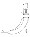
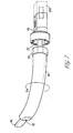
- Fig. 1 is a perspective view of an exemplary two-piece guide boot assembly with an angled section 10 and a straight section 20.
- a fiber optic cable 90 is shown extending through the guide boot 10 and straight section 20.
- the construction and design of fiber optic cable is known.
- Fiber optic cables may consist of a pair (or more) of thin channels or optic fibers formed of glass.
- the thin glass fibers are typically coated with ultraviolet-curable material for protection.
- the coated fibers are then covered with a thermoplastic material having sufficient stiffness to preclude fiber buckling.
- Strength yams or other suitable strength members surround the coated and covered fibers to withstand tensile forces, which can be caused by pulling on the fiber optic cable, which could otherwise break the fibers.
- the fiber optic cable 90 can be a fiber optic ribbon cable that is flexible, bendable, and twistable. As described earlier, the bend and twist of the cable must be controlled to limit signal loss.
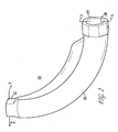
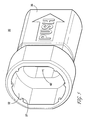
- Fig. 2 is a perspective view of guide boot 10.
- the guide boot 10 comprises an outer sleeve or body 15 that defines an inner passageway, and has a first end 12 for receiving the cable 90 and a termination port 17 through which cable 90 extends.
- the inner passageway is dimensioned to allow a user to insert a cable through the passageway.
- the portion of body 15 that defines the inner passageway is used for guiding, bending, and/or twisting (if desired) the cable 90.
- the body 15 is angled at a desired angle (ensuring a satisfactory radius of curvature), such as about 45 degrees or about 90 degrees, though any angle can be used as long as it does not affect the signal transmission of the cable 90.
- the body 15 preferably has an outer diameter that decreases toward the first end 12.
- the curved body 15 is preferably molded from a suitable non-flammable elastic material such as plastic.
- the first end 12 of guide boot 10 has an opening 13 (see Fig. 6) shaped similarly to the shape of cable 90 extending through the passageway.
- opening 13 is rectangular or oval shaped and slightly larger than cable 90.
- the termination port 17 acts as a lock ring and is adapted to connect to the termination plug 20.
- the termination port 17 has an opening 18 that is preferably round, but may be any shape that does not interfere with the ability of cable 90 to twist within the boot.
- the exterior of the termination port 17 is preferably shaped to be detachably connectable with the termination plug 20 (having an associated or complementary shape to receive the termination port 17 at multiple positions).
- the exterior of the termination port 17 can be any shape, such as the octagonal shape depicted in Figs. 2 and 6, as long as it can be appropriately connected with the termination plug 20 and serves to prevent angled section from rotating relative to straight section after being secured together.
- the inner passageway 40 is preferably tapered so as not to interfere with the twisting of cable 90.
- cable 90 is inserted into and through the guide boot 10 without any twisting (See Fig. 6), and the cable 90 is thereafter twisted or otherwise rotated immediately before the guide boot 10 is connected with the termination plug 20 (See Fig. 7).
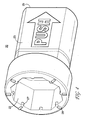
- Fig. 4 is a perspective view of an exemplary termination plug 20.
- the termination plug 20 has a first end 22 (shown here as having an interior octagonal-shape) to receive the cable 90 and to connect with the guide boot 10 using, for example, a friction fit in which an interior of the first end 22 grips the exterior of the termination port 17.
- a user would first rotate boot section 10 and then manually press the termination port 17 into the first end 22.
- Locking tabs 27 are preferably provided in the end 22 to engage the termination port 17 of the guide boot 10, thereby holding the guide boot in connection with the termination plug.
- Corresponding notches or openings can be provided in the termination port 17 to engage the locking tabs 27 or alignment marks 28.
- the termination plug 20 has a second end 25 that may receive a portion of connector 100, or be adapted to connect with a panel or other device (not shown). In this manner, the cable 90 is provided to a connector, the panel or other device.
- a straight boot portion 23 is disposed between the ends 22, 25.
- boot section 20 could be part of the optical connector where cable 90 terminates.
- Fig. 5 is a perspective view of another exemplary termination plug 30 in accordance with the present invention.
- the termination plug 30 has a first end 32 to receive the cable 90 within passageway 42 and to connect with the guide boot 10.
- the first end 32 has a modified shape to receive a corresponding or complementarily shaped termination port 17 at a limited number (i.e., one or two) of positions.
- the terminal plug 30 has a second end 35 that is adapted to receive a portion of connector 100, or to connect with a connector panel or other device (not shown). In this manner, the cable 90 is provided to the connector, panel or other device.
- termination plug 30 could be part of the optical connector where cable 90 terminates.
- passageway 42 is shaped similarly to the shape of cable 90. Similar to opening 13, passageway 42 has a shape and size to receive cable 90 and to receive a rear end of connector 100.
- Fig. 6 is a perspective view of a guide boot 10 with cable 90 extending there through.
- the cable 90 has the same orientation when inserted into the first end 12 and when exiting at the termination port 17.
- first section 10 Before securing first boot section 10 to second boot section 20, first section 10 must be rotated relative to second section 20.
- Fig. 7 is perspective view of a guide boot 10 rotated along arrow R and just prior to engaging termination plug 20 in accordance with the present invention.
- the attaching of sections 10 and 20 is preferably performed by pushing the guide boot 10 onto the termination plug 20, and more particularly, is performed by inserting the termination port 17 into the first end 22 of the termination plug.
- the connection is then maintained (locked) by locking tabs 27 provided on the termination plug 20 that hold the termination port 17.
- the shapes of port 17 and end 22 complement one another to prevent rotation of first boot section 10 after locking.
- the cable 90 initially extends through the guide boot 10 without any twisting.
- the cable 90 is subsequently twisted or otherwise rotated when the guide boot 10 is rotated and then connected with the termination plug 20. More particularly, in such an embodiment, the cable 90 does not initially change its orientation as it passes through the guide boot 10. However, the orientation of the cable 90 is thereafter changed after passing the end of cable 90 into passageway 42 by rotating the termination port 17 of the guide boot 10.
- the termination port 17 is then inserted into the first end 22 of the termination plug 20 to connect the two devices and prevent rotation, i.e., maintain orientation, of the pieces. In this manner, the rotation is achieved by the relative orientation of opening 13 and passageway 42 due to their shapes corresponding to cable 90.
- the cable 90 uses the entire length of first boot section 10 to rotate without interference.
- the termination port can be used to fix rotation to any amount that the user desires.
- the first end 22 of the termination plug 20 will have preset tabs, notches, or other indicators to indicate to a user various angles of cable rotation such as -45 degrees, +45 degrees, or 90 degrees.
- boot 10 could secure to plug 20 without any rotation if the user does not desire any twist on the cable 90, and merely requires an angled boot assembly. In this manner, providing the cable at a circumferential angle is less complex because the cable can be inserted into the guide boot without any twisting, and then be twisted when the guide boot is attached to the termination plug.
- the fiber optic cable assembly is assembled as follows.
- the cable 90 is inserted through the boot 10 and the plug 20. At this point, the boot 10 and the plug 20 are not connected together.
- the cable 90 is then terminated to the connector 100 in a known manner.
- the plug 20 is then secured to the connector 100, preferably by receiving the rear end of the connector 100 within the passageway 42 of the plug 20.
- the boot 10 is rotated, then secured to the plug 20.
- the cable assembly is now fully assembled.
- the cable assembly is then used to engage 'an adapter (not shown) on a panel (not shown) or other device.
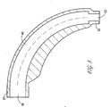
- Figures 9-10 show the preferred embodiment of first boot section 10.
- the mold pieces In order to mold a curved section having an internal passage extending between continuous ends (i. e. without a slit or other break in the material), the mold pieces (not shown) preferably have features (not shown) that also form cut out windows 14, 16 along the length of first boot section 10. This allows the mold pieces to be separated from the first boot section 10 after the molding process.
- the internal passage maintains a continuous surface C (see Fig. 10) along the outer diameter of the bend section. This continuous surface helps guide the cable 90 through the bend. If necessary, the user may assist the cable 90 through the bend by reaching into the passage through a window 14, 16.
- Fig. 11 is a perspective view of a guide boot 82 with a 45° bend. This arrangement could be used when the connector mounts, for example, to an adapter mounted at a 45° angle on a front panel.
Landscapes
- Physics & Mathematics (AREA)
- General Physics & Mathematics (AREA)
- Optics & Photonics (AREA)
- Details Of Connecting Devices For Male And Female Coupling (AREA)
- Installation Of Indoor Wiring (AREA)
- Light Guides In General And Applications Therefor (AREA)
- Details Of Indoor Wiring (AREA)
- Mechanical Coupling Of Light Guides (AREA)
- Protection Of Pipes Against Damage, Friction, And Corrosion (AREA)
- Endoscopes (AREA)
- Electric Cable Installation (AREA)
- Connector Housings Or Holding Contact Members (AREA)
- Surface Treatment Of Glass Fibres Or Filaments (AREA)
- Cable Accessories (AREA)
Applications Claiming Priority (2)
| Application Number | Priority Date | Filing Date | Title |
|---|---|---|---|
| US09/836,091 US6601997B2 (en) | 2001-04-17 | 2001-04-17 | Fiber optic cable guide boot |
| US836091 | 2001-04-17 |
Publications (4)
| Publication Number | Publication Date |
|---|---|
| EP1251379A2 true EP1251379A2 (de) | 2002-10-23 |
| EP1251379A3 EP1251379A3 (de) | 2004-10-06 |
| EP1251379B1 EP1251379B1 (de) | 2008-12-10 |
| EP1251379B8 EP1251379B8 (de) | 2009-03-11 |
Family
ID=25271220
Family Applications (1)
| Application Number | Title | Priority Date | Filing Date |
|---|---|---|---|
| EP02008206A Expired - Lifetime EP1251379B8 (de) | 2001-04-17 | 2002-04-17 | Führungsmanschette für Faseroptisches Kabel |
Country Status (7)
| Country | Link |
|---|---|
| US (1) | US6601997B2 (de) |
| EP (1) | EP1251379B8 (de) |
| JP (1) | JP3851209B2 (de) |
| CN (1) | CN1239934C (de) |
| AT (1) | ATE417294T1 (de) |
| CA (1) | CA2380906A1 (de) |
| DE (1) | DE60230212D1 (de) |
Cited By (2)
| Publication number | Priority date | Publication date | Assignee | Title |
|---|---|---|---|---|
| EP1260842A3 (de) * | 2001-05-14 | 2004-07-28 | Autonetworks Technologies, Ltd. | Optischer Steckverbinder |
| WO2012136702A1 (en) * | 2011-04-06 | 2012-10-11 | Fci | Cable guide boot assembly |
Families Citing this family (66)
| Publication number | Priority date | Publication date | Assignee | Title |
|---|---|---|---|---|
| US6734435B2 (en) * | 2001-05-29 | 2004-05-11 | Rae Systems, Inc. | Photo-ionization detector and method for continuous operation and real-time self-cleaning |
| US6672774B2 (en) * | 2001-10-05 | 2004-01-06 | Corning Cable Systems Llc | Post-connectorization boot, connectorized fiber optic cable assembly including same, and related methods |
| US7029182B2 (en) * | 2002-03-01 | 2006-04-18 | Fci Americas Technology, Inc. | Angled optical connector adapter mounting assembly |
| US6960030B2 (en) * | 2002-06-05 | 2005-11-01 | The Furukawa Electric Co., Ltd. | Optical connector boot with controlled rotation feature |
| US20030236020A1 (en) * | 2002-06-19 | 2003-12-25 | Joseph Iamartino | Field installable, field adjustable angled boot for multi-conductor cables and process for installing the same |
| US20040120656A1 (en) * | 2002-12-18 | 2004-06-24 | Vladimir Banas | Angled spring push for optical ribbon cable |
| US6817780B2 (en) * | 2003-01-15 | 2004-11-16 | Fci Americas Technology, Inc. | Guide boot for a fiber-optic cable |
| GB0322893D0 (en) * | 2003-09-30 | 2003-10-29 | British Telecomm | Telecommunications lead in apparatus |
| US7695197B2 (en) * | 2006-04-20 | 2010-04-13 | Tyco Electronics Corporation | Bend limiter |
| US7628545B2 (en) * | 2007-06-18 | 2009-12-08 | Corning Cable Systems Llc | Fiber optic plug assembly with boot and crimp band |
| US11294136B2 (en) | 2008-08-29 | 2022-04-05 | Corning Optical Communications LLC | High density and bandwidth fiber optic apparatuses and related equipment and methods |
| US8452148B2 (en) | 2008-08-29 | 2013-05-28 | Corning Cable Systems Llc | Independently translatable modules and fiber optic equipment trays in fiber optic equipment |
| ATE534049T1 (de) | 2009-02-24 | 2011-12-15 | Ccs Technology Inc | Haltevorrichtung für ein kabel oder eine anordnung zur verwendung mit einem kabel |
| US8699838B2 (en) | 2009-05-14 | 2014-04-15 | Ccs Technology, Inc. | Fiber optic furcation module |
| US9075216B2 (en) | 2009-05-21 | 2015-07-07 | Corning Cable Systems Llc | Fiber optic housings configured to accommodate fiber optic modules/cassettes and fiber optic panels, and related components and methods |
| WO2010148336A1 (en) | 2009-06-19 | 2010-12-23 | Corning Cable Systems Llc | High density and bandwidth fiber optic apparatuses and related equipment and methods |
| US8712206B2 (en) * | 2009-06-19 | 2014-04-29 | Corning Cable Systems Llc | High-density fiber optic modules and module housings and related equipment |
| USD628461S1 (en) * | 2009-09-25 | 2010-12-07 | Stein Jr Daniel L | Protective cover for wires |
| US20110129185A1 (en) * | 2009-11-30 | 2011-06-02 | Lewallen C Paul | Articulated Strain Relief Boot on a Fiber Optic Module and Associated Methods |
| US8625950B2 (en) | 2009-12-18 | 2014-01-07 | Corning Cable Systems Llc | Rotary locking apparatus for fiber optic equipment trays and related methods |
| US8593828B2 (en) * | 2010-02-04 | 2013-11-26 | Corning Cable Systems Llc | Communications equipment housings, assemblies, and related alignment features and methods |
| US8913866B2 (en) | 2010-03-26 | 2014-12-16 | Corning Cable Systems Llc | Movable adapter panel |
| AU2011265751B2 (en) | 2010-04-16 | 2015-09-10 | Corning Optical Communications LLC | Sealing and strain relief device for data cables |
| US9075217B2 (en) | 2010-04-30 | 2015-07-07 | Corning Cable Systems Llc | Apparatuses and related components and methods for expanding capacity of fiber optic housings |
| US8660397B2 (en) | 2010-04-30 | 2014-02-25 | Corning Cable Systems Llc | Multi-layer module |
| US8879881B2 (en) | 2010-04-30 | 2014-11-04 | Corning Cable Systems Llc | Rotatable routing guide and assembly |
| US9632270B2 (en) | 2010-04-30 | 2017-04-25 | Corning Optical Communications LLC | Fiber optic housings configured for tool-less assembly, and related components and methods |
| US9519118B2 (en) | 2010-04-30 | 2016-12-13 | Corning Optical Communications LLC | Removable fiber management sections for fiber optic housings, and related components and methods |
| US8705926B2 (en) | 2010-04-30 | 2014-04-22 | Corning Optical Communications LLC | Fiber optic housings having a removable top, and related components and methods |
| US9720195B2 (en) | 2010-04-30 | 2017-08-01 | Corning Optical Communications LLC | Apparatuses and related components and methods for attachment and release of fiber optic housings to and from an equipment rack |
| US8718436B2 (en) | 2010-08-30 | 2014-05-06 | Corning Cable Systems Llc | Methods, apparatuses for providing secure fiber optic connections |
| US9279951B2 (en) | 2010-10-27 | 2016-03-08 | Corning Cable Systems Llc | Fiber optic module for limited space applications having a partially sealed module sub-assembly |
| US8662760B2 (en) | 2010-10-29 | 2014-03-04 | Corning Cable Systems Llc | Fiber optic connector employing optical fiber guide member |
| US9116324B2 (en) | 2010-10-29 | 2015-08-25 | Corning Cable Systems Llc | Stacked fiber optic modules and fiber optic equipment configured to support stacked fiber optic modules |
| CA2819235C (en) | 2010-11-30 | 2018-01-16 | Corning Cable Systems Llc | Fiber device holder and strain relief device |
| WO2012106510A2 (en) | 2011-02-02 | 2012-08-09 | Corning Cable Systems Llc | Dense fiber optic connector assemblies and related connectors and cables suitable for establishing optical connections for optical backplanes in equipment racks |
| US9008485B2 (en) | 2011-05-09 | 2015-04-14 | Corning Cable Systems Llc | Attachment mechanisms employed to attach a rear housing section to a fiber optic housing, and related assemblies and methods |
| WO2013003303A1 (en) | 2011-06-30 | 2013-01-03 | Corning Cable Systems Llc | Fiber optic equipment assemblies employing non-u-width-sized housings and related methods |
| US8953924B2 (en) | 2011-09-02 | 2015-02-10 | Corning Cable Systems Llc | Removable strain relief brackets for securing fiber optic cables and/or optical fibers to fiber optic equipment, and related assemblies and methods |
| WO2012149798A1 (zh) * | 2011-10-09 | 2012-11-08 | 华为技术有限公司 | 布放尾纤的装置及方法 |
| DE102011085840B3 (de) * | 2011-11-07 | 2013-03-28 | Trumpf Laser Gmbh + Co. Kg | Vorrichtung zum Einstellen eines Strahlprofils, Laserbearbeitungsmaschine und Verfahren zur Herstellung der Vorrichtung |
| US9038832B2 (en) | 2011-11-30 | 2015-05-26 | Corning Cable Systems Llc | Adapter panel support assembly |
| US9250409B2 (en) | 2012-07-02 | 2016-02-02 | Corning Cable Systems Llc | Fiber-optic-module trays and drawers for fiber-optic equipment |
| US9042702B2 (en) | 2012-09-18 | 2015-05-26 | Corning Cable Systems Llc | Platforms and systems for fiber optic cable attachment |
| ES2551077T3 (es) | 2012-10-26 | 2015-11-16 | Ccs Technology, Inc. | Unidad de gestión de fibra óptica y dispositivo de distribución de fibra óptica |
| CN103033890B (zh) * | 2012-12-18 | 2016-01-20 | 中航光电科技股份有限公司 | 一种弯式活动光纤连接器 |
| US8985862B2 (en) | 2013-02-28 | 2015-03-24 | Corning Cable Systems Llc | High-density multi-fiber adapter housings |
| CN103151232B (zh) * | 2013-03-08 | 2015-10-14 | 中国人民解放军南京军区福州总医院 | 一种侧装光纤耦合透射电镜数字成像方法及其装置 |
| US9360649B2 (en) * | 2013-05-22 | 2016-06-07 | Senko Advanced Components, Inc. | Cable guide for fiber optic cables |
| US9720184B2 (en) * | 2015-02-04 | 2017-08-01 | International Business Machines Corporation | Blind mating strain relieved optical fiber connector |
| US9948075B2 (en) * | 2015-04-16 | 2018-04-17 | Oren Almog | Cable conduit shape holder device and method |
| CN104966924A (zh) * | 2015-05-14 | 2015-10-07 | 北京谷波技术有限公司 | 射频微波测试电缆直角转弯装置及制造的方法 |
| KR200489199Y1 (ko) * | 2016-11-28 | 2019-05-15 | 주식회사 위워너 | 광파이버용 가이드관 |
| KR200486952Y1 (ko) * | 2017-05-12 | 2018-07-17 | 삼성중공업(주) | 케이블 벤딩 장치 |
| USD908161S1 (en) | 2019-01-15 | 2021-01-19 | Moleculight, Inc. | Handheld imaging device |
| USD910182S1 (en) | 2019-01-17 | 2021-02-09 | Sbi Alapharma Canada, Inc. | Handheld multi-modal imaging device |
| EP3911222A4 (de) * | 2019-01-17 | 2023-02-01 | SBI Alapharma Canada, Inc. | Modulares endoskopisches system zur visualisierung von krankheiten |
| USD908881S1 (en) | 2019-01-17 | 2021-01-26 | Sbi Alapharma Canada, Inc. | Handheld endoscopic imaging device |
| WO2020148726A1 (en) | 2019-01-17 | 2020-07-23 | Moleculight Inc. | Modular system for multi-modal imaging and analysis |
| EP3911223A4 (de) | 2019-01-17 | 2022-10-19 | SBI Alapharma Canada, Inc. | Vorrichtungen, systeme und verfahren zur tumorvisualisierung und -entfernung |
| US10845542B1 (en) | 2019-08-19 | 2020-11-24 | Afl Telecommunications Llc | Cable node transition assemblies |
| KR102274378B1 (ko) * | 2020-05-22 | 2021-07-07 | 대원전기 주식회사 | 간접 활선용 전선 벤딩기 및 이를 이용한 전선 벤딩 간접 활선공법 |
| US12585077B2 (en) | 2021-01-27 | 2026-03-24 | Afl Telecommunications Llc | Fiber optic housing and clip |
| USD1117133S1 (en) | 2021-08-23 | 2026-03-10 | Moleculight Inc. | Modular handheld imaging device |
| CN116819706B (zh) * | 2023-07-04 | 2024-03-26 | 宏安集团有限公司 | 一种柔性可变的光纤带光缆 |
| WO2025248306A1 (en) * | 2024-05-31 | 2025-12-04 | Belden Canada Ulc | Cable guide structurally configured to route a cable in a selected direction as the cable extends from a connector |
Family Cites Families (19)
| Publication number | Priority date | Publication date | Assignee | Title |
|---|---|---|---|---|
| JPS62500546A (ja) * | 1984-10-03 | 1987-03-05 | ロツキ−ド・コ−ポレ−シヨン | 水中係合自在光ファイバ−コネクタ |
| US5073044A (en) | 1990-10-31 | 1991-12-17 | Amp Incorporated | Right angle strain relief for optical fiber connector |
| US5138678A (en) | 1991-09-20 | 1992-08-11 | Briggs Robert C | Connector with a variable direction strain relief |
| US5202942A (en) * | 1992-04-03 | 1993-04-13 | Amp Incorporated | Cable termination member for fiber optic connectors having improved strain relief |
| JPH05297246A (ja) * | 1992-04-22 | 1993-11-12 | Sumiden High Precision Kk | 光コネクタ |
| US5347603A (en) * | 1993-06-14 | 1994-09-13 | Molex Incorporated | Right angle cable strain relief |
| US5390272A (en) | 1993-08-31 | 1995-02-14 | Amphenol Corporation | Fiber optic cable connector with strain relief boot |
| US5425119A (en) * | 1993-09-23 | 1995-06-13 | Minnesota Mining And Manufacturing Company | Connector strain relief for optical fiber |
| DE4412571C1 (de) | 1994-04-13 | 1995-06-08 | Framatome Connectors Int | Kombinierter LWL-/Metallkabel-Steckverbinder |
| US5530787A (en) | 1995-02-28 | 1996-06-25 | At&T Corp | Optical fiber guide for preventing sharp bends |
| US5640476A (en) | 1995-07-14 | 1997-06-17 | Siecor Corporation | Guide sleeve for fiber optic cable |
| US5710851A (en) | 1995-11-06 | 1998-01-20 | Amphenol Corporation | Strain relief system for a fiber optic connector |
| US5781681A (en) | 1995-11-22 | 1998-07-14 | The Whitaker Corporation | Bend limiting strain relief boot |
| US5892871A (en) | 1995-12-13 | 1999-04-06 | Dahan; Michael | Fiber optic cable termination |
| US5933557A (en) | 1996-11-19 | 1999-08-03 | Siecor Corporation | Multi-link boot assembly for cable connector |
| US6019521A (en) | 1998-02-09 | 2000-02-01 | The Whitaker Corporation | Optical fiber connector |
| US6134370A (en) | 1998-10-30 | 2000-10-17 | Siecor Operations, Llc | Fiber optic cable guide |
| US6130983A (en) | 1998-12-23 | 2000-10-10 | Cheng; Yu-Feng | Rotatable L-shaped fiber optic connector |
| DE29900087U1 (de) * | 1999-01-05 | 1999-04-08 | Delphi Technologies, Inc., Troy, Mich. | Kabeldurchführung |
-
2001
- 2001-04-17 US US09/836,091 patent/US6601997B2/en not_active Expired - Lifetime
-
2002
- 2002-04-05 CA CA002380906A patent/CA2380906A1/en not_active Abandoned
- 2002-04-17 CN CNB021057680A patent/CN1239934C/zh not_active Expired - Fee Related
- 2002-04-17 AT AT02008206T patent/ATE417294T1/de not_active IP Right Cessation
- 2002-04-17 EP EP02008206A patent/EP1251379B8/de not_active Expired - Lifetime
- 2002-04-17 JP JP2002114359A patent/JP3851209B2/ja not_active Expired - Fee Related
- 2002-04-17 DE DE60230212T patent/DE60230212D1/de not_active Expired - Lifetime
Cited By (4)
| Publication number | Priority date | Publication date | Assignee | Title |
|---|---|---|---|---|
| EP1260842A3 (de) * | 2001-05-14 | 2004-07-28 | Autonetworks Technologies, Ltd. | Optischer Steckverbinder |
| US6905253B2 (en) | 2001-05-14 | 2005-06-14 | Autonetworks Technologies, Ltd. | Optical connector |
| WO2012136702A1 (en) * | 2011-04-06 | 2012-10-11 | Fci | Cable guide boot assembly |
| US9213145B2 (en) | 2011-04-06 | 2015-12-15 | FCI Asia PTE, Ltd. | Cable guide boot assembly |
Also Published As
| Publication number | Publication date |
|---|---|
| EP1251379B1 (de) | 2008-12-10 |
| EP1251379B8 (de) | 2009-03-11 |
| JP3851209B2 (ja) | 2006-11-29 |
| US6601997B2 (en) | 2003-08-05 |
| DE60230212D1 (de) | 2009-01-22 |
| EP1251379A3 (de) | 2004-10-06 |
| CN1381744A (zh) | 2002-11-27 |
| CA2380906A1 (en) | 2002-10-17 |
| CN1239934C (zh) | 2006-02-01 |
| JP2002357753A (ja) | 2002-12-13 |
| US20020150352A1 (en) | 2002-10-17 |
| ATE417294T1 (de) | 2008-12-15 |
Similar Documents
| Publication | Publication Date | Title |
|---|---|---|
| US6601997B2 (en) | Fiber optic cable guide boot | |
| CA2392176C (en) | Fiber optic cable guide boot | |
| US5640476A (en) | Guide sleeve for fiber optic cable | |
| US20260072220A1 (en) | Fiber optic connector | |
| US11994733B2 (en) | Fiber optic breakout transition assembly incorporating epoxy plug and cable strain relief | |
| JP4292238B2 (ja) | 光ファイバプラグと光ファイバレセプタクルの組立体 | |
| US5915056A (en) | Optical fiber strain relief device | |
| EP0629887B1 (de) | Rechtwinklig geführte Zugentlastung für Kabel | |
| US7703990B1 (en) | Furcation bodies and fiber optic assemblies using the same | |
| JP2008501151A (ja) | 多心光ファイバコネクタを有するあらかじめコネクタ接続加工された光ファイバ配線ケーブル | |
| CN1985205A (zh) | 光缆和插头组件 | |
| EP2216662A1 (de) | Spleißschutzvorrichtung für optische Spleiße und diese enthaldende faseroptische Kabelanordnung | |
| US11221456B2 (en) | Protective tube for micro-duct installation of fiber optic cable | |
| US8317410B2 (en) | Attachment of a connector to a fiber optic cable | |
| WO2025163322A1 (en) | Fibre optic connector, kits of parts and methods of using the same | |
| GB2637818A (en) | Fibre optic connector, kit of parts and methods of using same | |
| JP2000304974A (ja) | 光ファイバ用接続器 | |
| KR20110002571A (ko) | 광모드 컨버터 | |
| MXPA01005125A (es) | Adaptador de fibra optica, incluyendo un sistema conector hibrido |
Legal Events
| Date | Code | Title | Description |
|---|---|---|---|
| PUAI | Public reference made under article 153(3) epc to a published international application that has entered the european phase |
Free format text: ORIGINAL CODE: 0009012 |
|
| AK | Designated contracting states |
Kind code of ref document: A2 Designated state(s): AT BE CH CY DE DK ES FI FR GB GR IE IT LI LU MC NL PT SE TR |
|
| AX | Request for extension of the european patent |
Free format text: AL;LT;LV;MK;RO;SI |
|
| PUAL | Search report despatched |
Free format text: ORIGINAL CODE: 0009013 |
|
| AK | Designated contracting states |
Kind code of ref document: A3 Designated state(s): AT BE CH CY DE DK ES FI FR GB GR IE IT LI LU MC NL PT SE TR |
|
| AX | Request for extension of the european patent |
Extension state: AL LT LV MK RO SI |
|
| 17P | Request for examination filed |
Effective date: 20050329 |
|
| AKX | Designation fees paid |
Designated state(s): AT BE CH CY DE DK ES FI FR GB GR IE IT LI LU MC NL PT SE TR |
|
| 17Q | First examination report despatched |
Effective date: 20060627 |
|
| 17Q | First examination report despatched |
Effective date: 20060627 |
|
| GRAP | Despatch of communication of intention to grant a patent |
Free format text: ORIGINAL CODE: EPIDOSNIGR1 |
|
| GRAS | Grant fee paid |
Free format text: ORIGINAL CODE: EPIDOSNIGR3 |
|
| GRAA | (expected) grant |
Free format text: ORIGINAL CODE: 0009210 |
|
| AK | Designated contracting states |
Kind code of ref document: B1 Designated state(s): AT BE CH CY DE DK ES FI FR GB GR IE IT LI LU MC NL PT SE TR |
|
| REG | Reference to a national code |
Ref country code: GB Ref legal event code: FG4D |
|
| REG | Reference to a national code |
Ref country code: CH Ref legal event code: EP |
|
| RAP2 | Party data changed (patent owner data changed or rights of a patent transferred) |
Owner name: FCI |
|
| REG | Reference to a national code |
Ref country code: IE Ref legal event code: FG4D |
|
| REF | Corresponds to: |
Ref document number: 60230212 Country of ref document: DE Date of ref document: 20090122 Kind code of ref document: P |
|
| NLT2 | Nl: modifications (of names), taken from the european patent patent bulletin |
Owner name: FCI Effective date: 20090107 |
|
| PG25 | Lapsed in a contracting state [announced via postgrant information from national office to epo] |
Ref country code: NL Free format text: LAPSE BECAUSE OF FAILURE TO SUBMIT A TRANSLATION OF THE DESCRIPTION OR TO PAY THE FEE WITHIN THE PRESCRIBED TIME-LIMIT Effective date: 20081210 Ref country code: FI Free format text: LAPSE BECAUSE OF FAILURE TO SUBMIT A TRANSLATION OF THE DESCRIPTION OR TO PAY THE FEE WITHIN THE PRESCRIBED TIME-LIMIT Effective date: 20081210 |
|
| NLV1 | Nl: lapsed or annulled due to failure to fulfill the requirements of art. 29p and 29m of the patents act | ||
| PG25 | Lapsed in a contracting state [announced via postgrant information from national office to epo] |
Ref country code: BE Free format text: LAPSE BECAUSE OF FAILURE TO SUBMIT A TRANSLATION OF THE DESCRIPTION OR TO PAY THE FEE WITHIN THE PRESCRIBED TIME-LIMIT Effective date: 20081210 Ref country code: ES Free format text: LAPSE BECAUSE OF FAILURE TO SUBMIT A TRANSLATION OF THE DESCRIPTION OR TO PAY THE FEE WITHIN THE PRESCRIBED TIME-LIMIT Effective date: 20090321 |
|
| PG25 | Lapsed in a contracting state [announced via postgrant information from national office to epo] |
Ref country code: SE Free format text: LAPSE BECAUSE OF FAILURE TO SUBMIT A TRANSLATION OF THE DESCRIPTION OR TO PAY THE FEE WITHIN THE PRESCRIBED TIME-LIMIT Effective date: 20090310 Ref country code: AT Free format text: LAPSE BECAUSE OF FAILURE TO SUBMIT A TRANSLATION OF THE DESCRIPTION OR TO PAY THE FEE WITHIN THE PRESCRIBED TIME-LIMIT Effective date: 20081210 Ref country code: PT Free format text: LAPSE BECAUSE OF FAILURE TO SUBMIT A TRANSLATION OF THE DESCRIPTION OR TO PAY THE FEE WITHIN THE PRESCRIBED TIME-LIMIT Effective date: 20090511 |
|
| PLBE | No opposition filed within time limit |
Free format text: ORIGINAL CODE: 0009261 |
|
| STAA | Information on the status of an ep patent application or granted ep patent |
Free format text: STATUS: NO OPPOSITION FILED WITHIN TIME LIMIT |
|
| PG25 | Lapsed in a contracting state [announced via postgrant information from national office to epo] |
Ref country code: DK Free format text: LAPSE BECAUSE OF FAILURE TO SUBMIT A TRANSLATION OF THE DESCRIPTION OR TO PAY THE FEE WITHIN THE PRESCRIBED TIME-LIMIT Effective date: 20081210 |
|
| 26N | No opposition filed |
Effective date: 20090911 |
|
| REG | Reference to a national code |
Ref country code: CH Ref legal event code: PL |
|
| PG25 | Lapsed in a contracting state [announced via postgrant information from national office to epo] |
Ref country code: LI Free format text: LAPSE BECAUSE OF NON-PAYMENT OF DUE FEES Effective date: 20090430 Ref country code: CH Free format text: LAPSE BECAUSE OF NON-PAYMENT OF DUE FEES Effective date: 20090430 |
|
| PG25 | Lapsed in a contracting state [announced via postgrant information from national office to epo] |
Ref country code: IE Free format text: LAPSE BECAUSE OF NON-PAYMENT OF DUE FEES Effective date: 20090417 Ref country code: MC Free format text: LAPSE BECAUSE OF NON-PAYMENT OF DUE FEES Effective date: 20090430 |
|
| PG25 | Lapsed in a contracting state [announced via postgrant information from national office to epo] |
Ref country code: GR Free format text: LAPSE BECAUSE OF FAILURE TO SUBMIT A TRANSLATION OF THE DESCRIPTION OR TO PAY THE FEE WITHIN THE PRESCRIBED TIME-LIMIT Effective date: 20090311 |
|
| PG25 | Lapsed in a contracting state [announced via postgrant information from national office to epo] |
Ref country code: IT Free format text: LAPSE BECAUSE OF FAILURE TO SUBMIT A TRANSLATION OF THE DESCRIPTION OR TO PAY THE FEE WITHIN THE PRESCRIBED TIME-LIMIT Effective date: 20081210 |
|
| PG25 | Lapsed in a contracting state [announced via postgrant information from national office to epo] |
Ref country code: LU Free format text: LAPSE BECAUSE OF NON-PAYMENT OF DUE FEES Effective date: 20090417 |
|
| REG | Reference to a national code |
Ref country code: FR Ref legal event code: CA |
|
| PG25 | Lapsed in a contracting state [announced via postgrant information from national office to epo] |
Ref country code: TR Free format text: LAPSE BECAUSE OF FAILURE TO SUBMIT A TRANSLATION OF THE DESCRIPTION OR TO PAY THE FEE WITHIN THE PRESCRIBED TIME-LIMIT Effective date: 20081210 |
|
| PG25 | Lapsed in a contracting state [announced via postgrant information from national office to epo] |
Ref country code: CY Free format text: LAPSE BECAUSE OF FAILURE TO SUBMIT A TRANSLATION OF THE DESCRIPTION OR TO PAY THE FEE WITHIN THE PRESCRIBED TIME-LIMIT Effective date: 20081210 |
|
| REG | Reference to a national code |
Ref country code: DE Ref legal event code: R081 Ref document number: 60230212 Country of ref document: DE Owner name: FCI, FR Free format text: FORMER OWNER: FCI, VERSAILLES, FR Effective date: 20120419 |
|
| REG | Reference to a national code |
Ref country code: FR Ref legal event code: PLFP Year of fee payment: 15 |
|
| PGFP | Annual fee paid to national office [announced via postgrant information from national office to epo] |
Ref country code: FR Payment date: 20160331 Year of fee payment: 15 Ref country code: GB Payment date: 20160329 Year of fee payment: 15 |
|
| PGFP | Annual fee paid to national office [announced via postgrant information from national office to epo] |
Ref country code: DE Payment date: 20160414 Year of fee payment: 15 |
|
| REG | Reference to a national code |
Ref country code: DE Ref legal event code: R119 Ref document number: 60230212 Country of ref document: DE |
|
| GBPC | Gb: european patent ceased through non-payment of renewal fee |
Effective date: 20170417 |
|
| REG | Reference to a national code |
Ref country code: FR Ref legal event code: ST Effective date: 20171229 |
|
| PG25 | Lapsed in a contracting state [announced via postgrant information from national office to epo] |
Ref country code: DE Free format text: LAPSE BECAUSE OF NON-PAYMENT OF DUE FEES Effective date: 20171103 Ref country code: FR Free format text: LAPSE BECAUSE OF NON-PAYMENT OF DUE FEES Effective date: 20170502 |
|
| PG25 | Lapsed in a contracting state [announced via postgrant information from national office to epo] |
Ref country code: GB Free format text: LAPSE BECAUSE OF NON-PAYMENT OF DUE FEES Effective date: 20170417 |