EP1253268A2 - Schliessvorrichtung - Google Patents
Schliessvorrichtung Download PDFInfo
- Publication number
- EP1253268A2 EP1253268A2 EP02252692A EP02252692A EP1253268A2 EP 1253268 A2 EP1253268 A2 EP 1253268A2 EP 02252692 A EP02252692 A EP 02252692A EP 02252692 A EP02252692 A EP 02252692A EP 1253268 A2 EP1253268 A2 EP 1253268A2
- Authority
- EP
- European Patent Office
- Prior art keywords
- actuator
- latch assembly
- assembly according
- output
- latch
- Prior art date
- Legal status (The legal status is an assumption and is not a legal conclusion. Google has not performed a legal analysis and makes no representation as to the accuracy of the status listed.)
- Withdrawn
Links
Images


Classifications
-
- E—FIXED CONSTRUCTIONS
- E05—LOCKS; KEYS; WINDOW OR DOOR FITTINGS; SAFES
- E05B—LOCKS; ACCESSORIES THEREFOR; HANDCUFFS
- E05B77/00—Vehicle locks characterised by special functions or purposes
- E05B77/02—Vehicle locks characterised by special functions or purposes for accident situations
-
- E—FIXED CONSTRUCTIONS
- E05—LOCKS; KEYS; WINDOW OR DOOR FITTINGS; SAFES
- E05B—LOCKS; ACCESSORIES THEREFOR; HANDCUFFS
- E05B81/00—Power-actuated vehicle locks
- E05B81/12—Power-actuated vehicle locks characterised by the function or purpose of the powered actuators
- E05B81/14—Power-actuated vehicle locks characterised by the function or purpose of the powered actuators operating on bolt detents, e.g. for unlatching the bolt
-
- Y—GENERAL TAGGING OF NEW TECHNOLOGICAL DEVELOPMENTS; GENERAL TAGGING OF CROSS-SECTIONAL TECHNOLOGIES SPANNING OVER SEVERAL SECTIONS OF THE IPC; TECHNICAL SUBJECTS COVERED BY FORMER USPC CROSS-REFERENCE ART COLLECTIONS [XRACs] AND DIGESTS
- Y10—TECHNICAL SUBJECTS COVERED BY FORMER USPC
- Y10S—TECHNICAL SUBJECTS COVERED BY FORMER USPC CROSS-REFERENCE ART COLLECTIONS [XRACs] AND DIGESTS
- Y10S292/00—Closure fasteners
- Y10S292/23—Vehicle door latches
-
- Y—GENERAL TAGGING OF NEW TECHNOLOGICAL DEVELOPMENTS; GENERAL TAGGING OF CROSS-SECTIONAL TECHNOLOGIES SPANNING OVER SEVERAL SECTIONS OF THE IPC; TECHNICAL SUBJECTS COVERED BY FORMER USPC CROSS-REFERENCE ART COLLECTIONS [XRACs] AND DIGESTS
- Y10—TECHNICAL SUBJECTS COVERED BY FORMER USPC
- Y10S—TECHNICAL SUBJECTS COVERED BY FORMER USPC CROSS-REFERENCE ART COLLECTIONS [XRACs] AND DIGESTS
- Y10S292/00—Closure fasteners
- Y10S292/62—Lost motion connections
-
- Y—GENERAL TAGGING OF NEW TECHNOLOGICAL DEVELOPMENTS; GENERAL TAGGING OF CROSS-SECTIONAL TECHNOLOGIES SPANNING OVER SEVERAL SECTIONS OF THE IPC; TECHNICAL SUBJECTS COVERED BY FORMER USPC CROSS-REFERENCE ART COLLECTIONS [XRACs] AND DIGESTS
- Y10—TECHNICAL SUBJECTS COVERED BY FORMER USPC
- Y10S—TECHNICAL SUBJECTS COVERED BY FORMER USPC CROSS-REFERENCE ART COLLECTIONS [XRACs] AND DIGESTS
- Y10S292/00—Closure fasteners
- Y10S292/65—Emergency or safety
-
- Y—GENERAL TAGGING OF NEW TECHNOLOGICAL DEVELOPMENTS; GENERAL TAGGING OF CROSS-SECTIONAL TECHNOLOGIES SPANNING OVER SEVERAL SECTIONS OF THE IPC; TECHNICAL SUBJECTS COVERED BY FORMER USPC CROSS-REFERENCE ART COLLECTIONS [XRACs] AND DIGESTS
- Y10—TECHNICAL SUBJECTS COVERED BY FORMER USPC
- Y10T—TECHNICAL SUBJECTS COVERED BY FORMER US CLASSIFICATION
- Y10T292/00—Closure fasteners
- Y10T292/08—Bolts
- Y10T292/1043—Swinging
- Y10T292/1044—Multiple head
- Y10T292/1045—Operating means
- Y10T292/1047—Closure
-
- Y—GENERAL TAGGING OF NEW TECHNOLOGICAL DEVELOPMENTS; GENERAL TAGGING OF CROSS-SECTIONAL TECHNOLOGIES SPANNING OVER SEVERAL SECTIONS OF THE IPC; TECHNICAL SUBJECTS COVERED BY FORMER USPC CROSS-REFERENCE ART COLLECTIONS [XRACs] AND DIGESTS
- Y10—TECHNICAL SUBJECTS COVERED BY FORMER USPC
- Y10T—TECHNICAL SUBJECTS COVERED BY FORMER US CLASSIFICATION
- Y10T292/00—Closure fasteners
- Y10T292/08—Bolts
- Y10T292/1043—Swinging
- Y10T292/1075—Operating means
- Y10T292/1079—Gear
-
- Y—GENERAL TAGGING OF NEW TECHNOLOGICAL DEVELOPMENTS; GENERAL TAGGING OF CROSS-SECTIONAL TECHNOLOGIES SPANNING OVER SEVERAL SECTIONS OF THE IPC; TECHNICAL SUBJECTS COVERED BY FORMER USPC CROSS-REFERENCE ART COLLECTIONS [XRACs] AND DIGESTS
- Y10—TECHNICAL SUBJECTS COVERED BY FORMER USPC
- Y10T—TECHNICAL SUBJECTS COVERED BY FORMER US CLASSIFICATION
- Y10T292/00—Closure fasteners
- Y10T292/08—Bolts
- Y10T292/1043—Swinging
- Y10T292/1075—Operating means
- Y10T292/1082—Motor
Definitions
- the present invention relates to a latch assembly. More particularly, the present invention relates to a latch assembly having an actuator with two output modes.
- the present invention is particularly, although not exclusively, applicable to latches used on vehicle doors such as car passenger doors, tailgate doors or car boot doors.
- Vehicle door latches are known which are released using a power actuator.
- the present invention seeks to provide a latch arrangement having a relatively low power drive means that can be rapidly unlatch the door under normal conditions, and yet provide high unlatching forces in high seal force conditions.
- one aspect of the present invention provides a latch assembly for releasably securing a door in a closed position, the assembly comprising an actuator with an actuator output, the actuator having a first relatively fast acting low force output mode and a second relatively slow acting high force output mode, the actuator output being interconnected with a latch bolt of the assembly such that the latch bolt may be relatively rapidly released by the actuator operating in its first output mode when the load required to unlatch the latch bolt is relatively low, but relatively slowly unlatched by the second output mode when the load required to unlatch the latch bolt is relatively high.
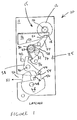
- a latch assembly 10 comprising a power actuator 15, a linkage 25 and a latch bolt 46 mounted on a plate 11. Normally, the latch assembly 10 would be mounted on a door (not shown) in use.
- the actuator comprises a motor 12 drivingly connected to a pinion 14 which in turn drivingly engages a rack provided on one edge of a cam 16.
- the opposite edge of the cam 16 is preferably provided with three distinct surfaces constituting the cam profile.
- the cam surfaces constitute the output of the actuator.
- the first surface 18 extends substantially parallel to the axis of travel of the cam, the second surface 20 has a relatively steep incline with respect to surface 18 and the third surface 22 has a relatively shallow incline with respect to surface 18.
- a cam follower 24 is pivotally mounted to plate 11 about pivot 27.
- a member 32 is also pivotally mounted to plate 11 by pivot 27.
- Resilient means which in this embodiment is a coil spring 30 is arranged about the pivot 27 so as to urge cam follower 24 anticlockwise and member 32 in clockwise directions.
- a stop (not shown) is preferably provided that prevents member 32 rotating in an anti-clock wise direction relative to follower 24 beyond a predetermined angle. The rotation of cam follower 24 clockwise relative to member 32 against the action of spring 30 is limited by a further stop 34 that engages with surface 28 of the cam follower 24.
- Pawl 38 is pivotally mounted for rotation about pivot 40 and is biased in a clockwise direction into contact with latch bolt 46 by resilient means (not shown).
- the end of the pawl 38 remote from member 32 includes a pawl tooth 44 for engagement with primary and secondary latching abutments 54 and 56 of the latch bolt 46.
- latch bolt 46 is of the rotating claw type, having a mouth 50 and being pivotally mounted on plate 11 about pivot 48. Plate 11 also includes a mouth 52 which in conjunction with the mouth 50 provides for the retention and release of a striker pin (not shown) mounted on an associated door aperture.
- the latch bolt is preferably resiliently biased to bring the mouth 50 into its open position.
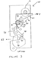
- a user wishing to open the door causes motor 12 to be energised, which in turn drives cam 16 in the direction Y shown in Figure 2.
- the power output of the motor is fixed, the unlatching force transmitted through the linkage 25 whilst the follower 24 is in contact with surface 20 is relatively low.
- the contact of the follower with surface 20 constitutes a first output mode of actuator 15.
- the seal force X1 acting on claw 46 is within normal operating range which could be expected to be between 300 and 600 N.
- the frictional resistance acting to prevent disengagement of pawl 244 from the primary latching abutment 54 is also relatively low and is less than the threshold force required to cause spring 30 to deflect. Therefore, as shown in Figure 2, the rotation of cam follower 24 causes member 32 to rotate clockwise and pawl 38 to rotate anti-clock wise thus rapidly disengaging pawl tooth 44 from primary latching abutment 54. In turn, this enables claw 46 to rotate anti-clock wise, thus releasing the striker and enabling the door to be opened.
- the cam then continues to be driven until the end of surface 22 is reached, before being reset to its starting position by reversing the motor drive.
- a sensor may be provided to ensure that the drive ceases once unlatching has been achieved and the cam position is then reset from that point.
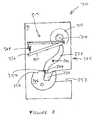
- the latch 110 comprises a rotatable claw 146 having a mouth 150 to receive and releaseably retain a striker 162.
- the claw further comprises a latching abutment 154 arranged to be engaged by pawl tooth 144 of pawl 138 that is rotatable about pivot 140.
- the pawl is biased into contact with the claw 146 by biasing means (not shown) such as a helical spring.
- a linkage comprising first and second arms 124 and 158 respectively interconnects the pawl 138 and a gear 116 of actuator 115.
- One end of arm 158 is pivotally mounted to pin 140 and a drive dog 141 is arranged to engage an edge of pawl 138 such that clockwise movement of arm 158 also results in clockwise movement of the pawl.
- the other end of arm 158 is pivotally mounted to one end of arm 124 by pivot pin 127.
- the other end of arm 124 has a pin 125 mounted thereon.
- Pin 125 is mounted for slideable movement within schematically illustrated slot 160 on actuator gear 116.
- Pin 125 is resiliently biased towards the radially outer edge of gear 116 by biasing means in the form of a helical compression spring illustrated schematically at 164, with the other end of the spring being secured to a fixed point the gear 116.
- the slot 160 has an arcuate profile whose radius of curvature is variable over its length.
- the compression spring 164 may fit within slot 160.
- the latch starts in a latched condition shown in Figure 5 and to achieve unlatching, actuator gear 116 is driven in a clockwise direction Y' by drive means such as an electric motor (not shown).
- the pin in slot arrangement enables the actuator to provide the optimum force to the pawl tooth 144 such that for a given the amount of energy supplied to the actuator, the fastest possible unlatching may occur.
- the length and shape of the slot 160, power output and gearing of the motor and the resilience of the spring 164 all may be adjusted to provide the appropriate ranges of unlatching force and unlatching speed for a given latch.
- there may be no pre-loading on spring 164 meaning that any frictional resistance to the disengagement of the pawl tooth 144 will cause compression of the spring.
- spring 164 may be replaced by a tension spring 164a illustrated in broken lines in Figure 5 and which is secured to the mounting plate (not shown) of the latch 110.
- a sensor may be provided in the latch assembly 110 to detect when disengagement of the pawl tooth 144 is achieved and drive from the actuator may then cease.
- the actuator may be caused to drive to its full extent of rotation before drive is caused to cease (e.g. by monitoring changes in current to the motor and detecting a change in this when the motor stalls). In both cases, the actuator is then back driven, either by reversing the actuator motor, or by use of resilient means (not shown) to return to its rest position.
- a clutch may be provided between the motor and the actuator gear 116 so that back-driving the motor is not necessary.
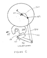
- first link 216 mounted to be driven by drive means (not shown) about point 217.
- First link 216 is pivotally mounted to second link 219 about pin 221 remote from point 217, with linkage 224 being further pivotally mounted to the second link 219 about pin 225 remote from pin 221.
- First and second links 216 and 219 are biased into a substantially parallel relationship of their longitudinal axes by torsion spring 264 mounted about pin 221.
- the drive means rotates link 216 in a clockwise direction Y". If the unlatching force required is relatively low, the resilience of spring 221 is not overcome, the rotation of link 216 is translated to substantially linear movement of linkage member 224, with links 216 and 219 remaining mutually parallel. However, if the required unlatching force is increased for any reason, the resistance to unlatching causes link 219 to pivot anticlockwise in relation to link 216, thereby shortening the effective lever length between point 217 and pin 225. This increases the unlatching force at the expense of the speed at which unlatching is achieved.
- the arrangement of the third embodiment also self-regulates the relationship between the output force supplied by actuator 215 to achieve unlatching, and the output speed of the actuator.
- the position of pawl tooth 244 and second linkage member 258 when released is illustrated in broken lines in Figure 7.
- a similar arrangement to the second embodiment maybe provided to enable the actuator to return to its rest position once unlatching has been achieved.
- cam 316 of power actuator 315 self-regulates to achieve the optimum rate of unlatching for a given unlatching force.
Landscapes
- Lock And Its Accessories (AREA)
Applications Claiming Priority (2)
| Application Number | Priority Date | Filing Date | Title |
|---|---|---|---|
| GB0110456 | 2001-04-28 | ||
| GBGB0110456.1A GB0110456D0 (en) | 2001-04-28 | 2001-04-28 | Latch assembly |
Publications (2)
| Publication Number | Publication Date |
|---|---|
| EP1253268A2 true EP1253268A2 (de) | 2002-10-30 |
| EP1253268A3 EP1253268A3 (de) | 2004-02-04 |
Family
ID=9913664
Family Applications (1)
| Application Number | Title | Priority Date | Filing Date |
|---|---|---|---|
| EP02252692A Withdrawn EP1253268A3 (de) | 2001-04-28 | 2002-04-16 | Schliessvorrichtung |
Country Status (3)
| Country | Link |
|---|---|
| US (1) | US6773042B2 (de) |
| EP (1) | EP1253268A3 (de) |
| GB (1) | GB0110456D0 (de) |
Cited By (5)
| Publication number | Priority date | Publication date | Assignee | Title |
|---|---|---|---|---|
| WO2014090212A3 (de) * | 2012-12-15 | 2014-10-09 | Kiekert Aktiengesellschaft | Kraftfahrzeugtürschloss |
| WO2016078639A1 (de) * | 2014-11-20 | 2016-05-26 | Kiekert Ag | Elektroschloss mit betätigungseinrichtung für ein kraftfahrzeugschloss nebst verfahren |
| WO2018006896A1 (de) * | 2016-07-04 | 2018-01-11 | Kiekert Ag | Kraftfahrzeugschloss |
| CN109415911A (zh) * | 2016-06-10 | 2019-03-01 | 开开特股份公司 | 机动车锁 |
| WO2019233523A1 (de) * | 2018-06-08 | 2019-12-12 | Kiekert Ag | Elektrisch betätigbares kraftfahrzeugschloss |
Families Citing this family (41)
| Publication number | Priority date | Publication date | Assignee | Title |
|---|---|---|---|---|
| DE10312304B4 (de) * | 2003-03-20 | 2005-12-29 | Brose Schließsysteme GmbH & Co.KG | Kraftffahrzeugschloß |
| DE10320447A1 (de) * | 2003-05-08 | 2004-11-25 | Kiekert Ag | Kraftfahrzeugtürverschluss |
| CA2439780C (en) * | 2003-09-08 | 2011-09-20 | Intier Automotive Closures Inc. | Power actuator for automotive closure latch |
| US20070126244A1 (en) * | 2003-09-09 | 2007-06-07 | Intier Automotive Closures Inc. | Power Actuator for Automotive Closure Latch |
| US20060010943A1 (en) * | 2004-07-13 | 2006-01-19 | Lear Corporation | Mechanical handle switch assembly |
| EP2155991B1 (de) * | 2007-05-25 | 2015-09-09 | Magna Closures Inc. | Schloss, insbesondere für kofferraum, mit elektro-mechanisch betätigtem schneelasthebel |
| GB2460088B (en) * | 2008-05-16 | 2012-05-09 | Ge Aviat Systems Ltd | Locking assembly |
| DE102008028256A1 (de) * | 2008-06-13 | 2009-12-24 | Kiekert Ag | Schließvorrichtung mit zwei Sperrklinken und motorisch angetriebenen Stellantrieb |
| CN102084076B (zh) * | 2008-06-13 | 2013-03-27 | 开开特股份公司 | 一种锁定设备 |
| GB2464311B (en) | 2008-10-13 | 2012-08-15 | Huf Huelsbeck & Fuerst Gmbh & Co Kg | Latch mechanism with inertia event sensor |
| US7869198B1 (en) * | 2009-03-11 | 2011-01-11 | Daktronics, Inc. | Multiple seal electronic display module having displacement springs |
| DE102010003483B4 (de) * | 2009-06-12 | 2019-08-01 | Kiekert Ag | Schloss mit Zwangsführung für Sperrklinke |
| US8333412B2 (en) * | 2009-07-17 | 2012-12-18 | Scranton Products Inc. | Locker |
| US20110133492A1 (en) * | 2009-12-08 | 2011-06-09 | Perkins Donald M | Vehicle door latch |
| DE102009044832B4 (de) * | 2009-12-09 | 2011-12-22 | Sfs Intec Holding Ag | Schloss für eine Gepäckbox |
| US8528950B2 (en) | 2010-02-01 | 2013-09-10 | Strattec Security Corporation | Latch mechanism and latching method |
| EP2531680B1 (de) * | 2010-02-05 | 2018-10-24 | Magna Closures SpA | Fahrzeugverriegelung mit doppelklinkenanordnung |
| USD653932S1 (en) | 2010-03-30 | 2012-02-14 | Scranton Products Inc. | Locker handle |
| US20120175896A1 (en) * | 2010-05-05 | 2012-07-12 | Alfredo Martinez | Vehicle door latch |
| DE102011011662B4 (de) * | 2011-02-18 | 2018-09-20 | Emz-Hanauer Gmbh & Co. Kgaa | Geschirrspülmaschine mit einem Türverschluss |
| JP5437309B2 (ja) * | 2011-04-22 | 2014-03-12 | アイシン精機株式会社 | 回転レバーの位置保持装置および該回転レバーの位置保持装置を備える車両用ドアロック装置 |
| DE202012002867U1 (de) * | 2012-03-20 | 2012-04-11 | Flexngate Automotive Iberica S.A. | Schloss mit Drehriegel |
| DE102012023236A1 (de) * | 2012-11-28 | 2014-05-28 | Kiekert Aktiengesellschaft | Kraftfahrzeugtürschloss |
| JP5983376B2 (ja) * | 2012-12-10 | 2016-08-31 | アイシン精機株式会社 | 回転レバーの位置保持装置 |
| US9920555B2 (en) * | 2013-01-18 | 2018-03-20 | Kiekert Ag | Lock for a motor vehicle |
| US9593511B2 (en) | 2013-03-27 | 2017-03-14 | Kiekert Ag | Lock for a motor vehicle |
| US9212509B2 (en) * | 2013-03-27 | 2015-12-15 | Kiekert Ag | Locking mechanism |
| DE102014105771A1 (de) * | 2013-04-29 | 2014-10-30 | GM Global Technology Operations LLC (n. d. Gesetzen des Staates Delaware) | Steuerung für die Lösekraft einer Verriegelungsanordnung und Verfahren dafür |
| US9809999B2 (en) * | 2013-11-25 | 2017-11-07 | The Eastern Company | Latch apparatus |
| GB201408075D0 (en) * | 2014-05-07 | 2014-06-18 | Chevalier John P | Closure and latching mechanisms |
| US10669750B2 (en) | 2014-05-30 | 2020-06-02 | Inteva Products, Llc | Latch with hold open lever |
| US10577839B2 (en) * | 2015-06-11 | 2020-03-03 | Inteva Products, Llc | Over center mechanism and method of use |
| DE102017209376A1 (de) * | 2016-06-07 | 2017-12-07 | Magna Closures Inc. | Fahrzeugverschluss-Verriegelungsanordnung mit Doppelklinken-Verriegelungsmechanismus |
| KR20180092293A (ko) * | 2017-02-08 | 2018-08-17 | 인테바 프로덕츠 엘엘씨. | 차량 래치에서의 균일한 해제 작용력을 위한 장치 및 방법 |
| IT201800004000A1 (it) * | 2018-03-27 | 2019-09-27 | Illinois Tool Works | Blocco-porta per elettrodomestici, in particolare lavatrici e simili, con meccanismo di riduzione di forza perfezionato |
| US11346129B1 (en) | 2018-11-16 | 2022-05-31 | The Eastern Company | Latch apparatus |
| DE102021102559A1 (de) | 2021-02-04 | 2022-08-04 | Kiekert Aktiengesellschaft | Elektromotorischer Antrieb für kraftfahrzeug-technische Anwendungen |
| DE102021102560A1 (de) * | 2021-02-04 | 2022-08-04 | Kiekert Aktiengesellschaft | Elektromotorischer Antrieb für kraftfahrzeug-technische Anwendungen |
| DE102021106210A1 (de) * | 2021-03-15 | 2022-09-15 | Kiekert Aktiengesellschaft | Elektromotorischer Antrieb für kraftfahrzeugtechnische Anwendungen |
| US12503883B2 (en) * | 2022-07-27 | 2025-12-23 | Ts Tech Co., Ltd. | Locking device and vehicle seat with locking device |
| US20250101781A1 (en) * | 2023-09-22 | 2025-03-27 | Illinois Tool Works Inc. | Ice Break Emergency Release |
Family Cites Families (25)
| Publication number | Priority date | Publication date | Assignee | Title |
|---|---|---|---|---|
| US3479767A (en) * | 1968-03-11 | 1969-11-25 | Newell J Gardner | Emergency door opener for automobiles |
| JPS58207468A (ja) | 1982-05-28 | 1983-12-02 | 三井金属鉱業株式会社 | ロック装置 |
| IL80536A (en) * | 1986-11-07 | 1990-11-05 | Mordechai Yirmiyahu | Device for force-opening doors |
| US5107194A (en) * | 1989-08-14 | 1992-04-21 | Xerox Corporation | Stepper motor control to vary output torque |
| IT1241959B (it) * | 1990-04-13 | 1994-02-01 | So Ge Mi Spa | Cinematismo atto a garantire un carico zero, a fine corsa, sugli attuatori per la chiusura e l'apertura automatica delle portiere delleautovetture. |
| JP2582178B2 (ja) * | 1990-07-19 | 1997-02-19 | 日産自動車株式会社 | フードロック装置 |
| JP3029478B2 (ja) | 1991-06-05 | 2000-04-04 | アスモ株式会社 | シフトロックアクチュエータの駆動制御回路 |
| US5280881A (en) * | 1992-09-29 | 1994-01-25 | Donald Karmin | High security locking device |
| JP3074116B2 (ja) | 1994-12-12 | 2000-08-07 | 株式会社大井製作所 | ドアクロージャ |
| US5956998A (en) * | 1996-06-06 | 1999-09-28 | Fenelon; Paul J. | Stress reduction gear and apparatus using same |
| DE19710531B4 (de) * | 1997-03-14 | 2007-01-18 | Brose Schließsysteme GmbH & Co.KG | Kraftfahrzeug-Türschloß |
| GB2328241B (en) * | 1997-05-21 | 2001-06-13 | Rockwell Lvs | Door mechanism |
| DE19725416C1 (de) | 1997-06-17 | 1999-01-21 | Huf Huelsbeck & Fuerst Gmbh | Drehfallenschloß, insbesondere für Kraftfahrzeuge |
| GB2337555A (en) | 1998-05-22 | 1999-11-24 | Meritor Light Vehicle Sys Ltd | Vehicle door latch power actuator |
| US6021691A (en) * | 1998-06-11 | 2000-02-08 | Wilkerson, Jr.; Clarence | Manual override for power windows |
| FR2782110B1 (fr) | 1998-08-05 | 2000-10-06 | Valeo Securite Habitacle | Serrure de porte a assistance electrique |
| FR2782111B1 (fr) * | 1998-08-05 | 2002-12-06 | Valeo Securite Habitacle | Serrure electrique perfectionnee pour ouvrant de vehicule automobile |
| DE19935589A1 (de) * | 1999-08-02 | 2001-02-15 | Bosch Gmbh Robert | Kraftfahrzeug-Türschloß o. dgl. |
| DE19937943A1 (de) * | 1999-08-11 | 2001-03-01 | Bosch Gmbh Robert | Maximale Leistung für Öffnung eines Elektrodenschlosses |
| DE19948052A1 (de) * | 1999-10-06 | 2001-04-12 | Mannesmann Vdo Ag | Öffnungshilfe für Türschlösser |
| DE19955882C2 (de) * | 1999-11-20 | 2003-10-23 | Kiekert Ag | Kraftfahrzeugtürverschluss |
| US6412584B1 (en) * | 1999-12-09 | 2002-07-02 | Trw Vehicle Safety Systems Inc. | Vehicle door opener |
| US6459223B2 (en) * | 2000-05-03 | 2002-10-01 | Robert Bosch Gmbh | Motor vehicle door lock and process for its control |
| US6354121B1 (en) * | 2000-07-21 | 2002-03-12 | Harrow Products, Inc. | Mortise lockset with internal clutch |
| US6550831B2 (en) * | 2001-04-13 | 2003-04-22 | Tekdata Inc. | Lock and emergency release system for power operated doors |
-
2001
- 2001-04-28 GB GBGB0110456.1A patent/GB0110456D0/en not_active Ceased
-
2002
- 2002-04-16 EP EP02252692A patent/EP1253268A3/de not_active Withdrawn
- 2002-04-24 US US10/131,586 patent/US6773042B2/en not_active Expired - Fee Related
Cited By (9)
| Publication number | Priority date | Publication date | Assignee | Title |
|---|---|---|---|---|
| WO2014090212A3 (de) * | 2012-12-15 | 2014-10-09 | Kiekert Aktiengesellschaft | Kraftfahrzeugtürschloss |
| US9845624B2 (en) | 2012-12-15 | 2017-12-19 | Kiekert Aktiengesellschaft | Lock for a motor vehicle door |
| RU2652580C2 (ru) * | 2012-12-15 | 2018-04-26 | Кикерт Акциенгезелльшафт | Дверной замок транспортного средства |
| WO2016078639A1 (de) * | 2014-11-20 | 2016-05-26 | Kiekert Ag | Elektroschloss mit betätigungseinrichtung für ein kraftfahrzeugschloss nebst verfahren |
| CN109415911A (zh) * | 2016-06-10 | 2019-03-01 | 开开特股份公司 | 机动车锁 |
| CN109415911B (zh) * | 2016-06-10 | 2021-05-28 | 开开特股份公司 | 机动车锁 |
| WO2018006896A1 (de) * | 2016-07-04 | 2018-01-11 | Kiekert Ag | Kraftfahrzeugschloss |
| US11377882B2 (en) | 2016-07-04 | 2022-07-05 | Kiekert Ag | Motor vehicle lock |
| WO2019233523A1 (de) * | 2018-06-08 | 2019-12-12 | Kiekert Ag | Elektrisch betätigbares kraftfahrzeugschloss |
Also Published As
| Publication number | Publication date |
|---|---|
| US6773042B2 (en) | 2004-08-10 |
| GB0110456D0 (en) | 2001-06-20 |
| US20020167178A1 (en) | 2002-11-14 |
| EP1253268A3 (de) | 2004-02-04 |
Similar Documents
| Publication | Publication Date | Title |
|---|---|---|
| EP1253268A2 (de) | Schliessvorrichtung | |
| US8146964B2 (en) | Support mechanism and a latch mechanism | |
| JP5541630B2 (ja) | 補助ドアロック機構を備える電動スイングプラグドアオペレータ | |
| EP2113048B1 (de) | Verriegelungsanordnung | |
| EP1820926B1 (de) | Verriegelungsanordnung | |
| JP2008530407A (ja) | ラッチ組立体 | |
| EP1190153B1 (de) | Verriegelungsvorrichtung | |
| CN104169510A (zh) | 汽车门锁 | |
| EP1710377A2 (de) | Kraftangetriebene Schliessvorrichtung | |
| CN104169509B (zh) | 用于舱盖或门的锁 | |
| US20160340939A1 (en) | Locking device for a motor vehicle hood, and method | |
| US20060267351A1 (en) | Latch for a vehicle | |
| EP3599331B1 (de) | Zuziehüberbrückungsmechanismus für verriegelungsanordnung | |
| US6536814B2 (en) | Motor vehicle door lock with a controlled actuating element | |
| CN117120697A (zh) | 机动车锁 | |
| JP2024531632A (ja) | 自動車用ロック、特に、自動車ドア用ロック | |
| EP1176273B1 (de) | Schliessvorrichtung | |
| US7472628B2 (en) | Door handle input decoupler for a cinching latch actuator | |
| EP1256683B1 (de) | Schnell-Lösevorrichtung für eine elektrische Bustür | |
| US11680435B2 (en) | Single drive system for driving multiple driven assemblies | |
| EP1149967B1 (de) | Verriegelungsvorrichtung | |
| CN113195854B (zh) | 用于机动车的锁 | |
| JP2003227263A (ja) | ドアロック駆動装置 | |
| WO2025061215A1 (en) | Automobile lock | |
| CN120251012A (zh) | 一种车门锁 |
Legal Events
| Date | Code | Title | Description |
|---|---|---|---|
| PUAI | Public reference made under article 153(3) epc to a published international application that has entered the european phase |
Free format text: ORIGINAL CODE: 0009012 |
|
| AK | Designated contracting states |
Kind code of ref document: A2 Designated state(s): AT BE CH CY DE DK ES FI FR GB GR IE IT LI LU MC NL PT SE TR |
|
| AX | Request for extension of the european patent |
Free format text: AL;LT;LV;MK;RO;SI |
|
| PUAL | Search report despatched |
Free format text: ORIGINAL CODE: 0009013 |
|
| AK | Designated contracting states |
Kind code of ref document: A3 Designated state(s): AT BE CH CY DE DK ES FI FR GB GR IE IT LI LU MC NL PT SE TR |
|
| AX | Request for extension of the european patent |
Extension state: AL LT LV MK RO SI |
|
| RIC1 | Information provided on ipc code assigned before grant |
Ipc: 7E 05B 65/12 B Ipc: 7E 05B 65/19 A |
|
| 17P | Request for examination filed |
Effective date: 20040709 |
|
| AKX | Designation fees paid |
Designated state(s): DE FR GB |
|
| 17Q | First examination report despatched |
Effective date: 20061019 |
|
| RAP1 | Party data changed (applicant data changed or rights of an application transferred) |
Owner name: MERITOR TECHNOLOGY, INC. |
|
| STAA | Information on the status of an ep patent application or granted ep patent |
Free format text: STATUS: THE APPLICATION IS DEEMED TO BE WITHDRAWN |
|
| 18D | Application deemed to be withdrawn |
Effective date: 20101102 |