EP1255655B1 - Kupplungsvorrichtung - Google Patents
Kupplungsvorrichtung Download PDFInfo
- Publication number
- EP1255655B1 EP1255655B1 EP01904765A EP01904765A EP1255655B1 EP 1255655 B1 EP1255655 B1 EP 1255655B1 EP 01904765 A EP01904765 A EP 01904765A EP 01904765 A EP01904765 A EP 01904765A EP 1255655 B1 EP1255655 B1 EP 1255655B1
- Authority
- EP
- European Patent Office
- Prior art keywords
- coupling
- end part
- trailer
- coupling end
- main portion
- Prior art date
- Legal status (The legal status is an assumption and is not a legal conclusion. Google has not performed a legal analysis and makes no representation as to the accuracy of the status listed.)
- Expired - Lifetime
Links
Images


Classifications
-
- B—PERFORMING OPERATIONS; TRANSPORTING
- B60—VEHICLES IN GENERAL
- B60D—VEHICLE CONNECTIONS
- B60D1/00—Traction couplings; Hitches; Draw-gear; Towing devices
- B60D1/58—Auxiliary devices
- B60D1/62—Auxiliary devices involving supply lines, electric circuits or the like
- B60D1/64—Couplings or joints therefor
-
- H—ELECTRICITY
- H01—ELECTRIC ELEMENTS
- H01R—ELECTRICALLY-CONDUCTIVE CONNECTIONS; STRUCTURAL ASSOCIATIONS OF A PLURALITY OF MUTUALLY-INSULATED ELECTRICAL CONNECTING ELEMENTS; COUPLING DEVICES; CURRENT COLLECTORS
- H01R13/00—Details of coupling devices of the kinds covered by groups H01R12/70 or H01R24/00 - H01R33/00
- H01R13/005—Electrical coupling combined with fluidic coupling
-
- H—ELECTRICITY
- H01—ELECTRIC ELEMENTS
- H01R—ELECTRICALLY-CONDUCTIVE CONNECTIONS; STRUCTURAL ASSOCIATIONS OF A PLURALITY OF MUTUALLY-INSULATED ELECTRICAL CONNECTING ELEMENTS; COUPLING DEVICES; CURRENT COLLECTORS
- H01R2201/00—Connectors or connections adapted for particular applications
- H01R2201/26—Connectors or connections adapted for particular applications for vehicles
Definitions
- the present invention relates to a trailer coupling for connecting a traction vehicle to a trailer, a coupling part mounted at the back of the vehicle being adapted to receive a coupling end part of a drawbar fixed to the trailer, said coupling end part being connected to the drawbar via a joint, and a locking mechanism being adapted to fix the coupling end part to the coupling part so as to secure the mechanical connection of the vehicle to the trailer.
- DE 849,658 where means for connecting air lines is arranged at the end of a coupling end part provided with teeth. Like in SE 396,730, a final rectilinear motion is ensured, during which a connection of the air line is ensured. At the coupling part there is also arranged a system with gear wheels and link arms, which in cooperation with the teeth of the coupling end part ensures connection of an electric wire while at the same time the coupling end part is brought in place.
- DE 930,063 shows another example, where means for connecting electric wires and an air line are provided at the front of the coupling end part.
- connection of air takes place at the same time as the mechanical connection, there is also a risk that the trailer is provided with air before the mechanical connection has been 100 percent secured. This may result in the brakes of the trailer being released before the trailer has been secured, the trailer thus moving away from the vehicle. Even if the brakes, of course, are again locked as soon as the trailer moves away from the vehicle, people in the absolute vicinity of the trailer run the risk of being injured.
- the trailer according to DE 849,658 would be provided with air but not with electric power since electric power and air are connected independently of each other.
- a first object of the present invention is to provide a trailer coupling which enables connection of electric wires and fluid lines automatically in connection with the mechanical connection, without the problems described above.
- a second object of the invention is to provide a coupling which is easy and quick to handle.
- a trailer coupling of the type described by way of introduction wherein the coupling end part has an essentially wedge-shaped main portion, and that the coupling part has a receiving space which is adapted to the shape of said main portion.
- the trailer coupling comprises separately operable means for connecting fluid lines as well as electric wires of the vehicle and the trailer respectively, said means being arranged to be operable to secure connection of said electric wires and fluid lines through suitably positioned holes in respectively the receiving space and the main portion of the coupling end part only when the coupling end part has been mechanically secured in the coupling part by means of the locking mechanism.
- the wedge-shaped coupling end part fits exactly in the coupling part.
- This wedge shape ensures alignment of the coupling end part with the coupling part in all directions at the same time.
- wedge-shaped is meant also other shapes having these properties, such as semi-oval, rhombic, etc.
- the connecting means for electric wire and fluid line are operated to secure the connection between trailer and vehicle.
- the connecting means Since the connection of electric power and pneumatics takes place after the fixing of the coupling end part, the connecting means are not subjected to the great forces that occur in connection with movements between vehicle and trailer before they have been mechanically secured.
- the connecting means comprise first connectors arranged at the coupling part, which are insertable through holes in the coupling end part in order to secure the connection of the fluid lines and the electric wires through cooperation with other connectors which are arranged in the coupling end part and positioned behind said holes.
- the connection of the electric wires and fluid lines thus takes place through holes in the coupling end part, which in this case has an inner space in which said second connectors are arranged.
- the first connectors can be of a male type, such as pin-shaped electric contacts or projecting fluid nozzles. They can be arranged to be pushed in their longitudinal direction towards the coupling end part and penetrate holes in the same.
- connection takes place by a motion, preferably a rectilinear motion, which is easy to guide and control. It is also easy to ensure that the connectors are well protected since on the one hand they are arranged inside the coupling end part and, on the other hand, they are movable and thus can be inserted in some kind of protective means.
- the movable and fixed connectors can be reversed, and optionally the connectors in both coupling part and coupling end part can be movable.
- the holes are slightly larger than the cross-sectional area of the connectors and can also be provided with cover means to reduce the risk of dirt and moisture penetrating through the holes.
- a sensor is arranged in connection with the locking mechanism for detecting when the mechanical connection is secured, and thus enable time-controlled operation of the connectors. This makes it possible to carry out the connection of electric wires and fluid lines automatically and in immediate connection with the mechanical connection, thereby avoiding the need for two operations.
- the coupling end part can be arranged to be in contact, when inserted into the coupling part, with the coupling part along elongate contact surfaces which only occupy a small part of the total circumferential surface of the coupling end part. In this way, contact with the coupling part is minimised, thus minimising the risk of dirt and other particles impeding the mechanical connection.
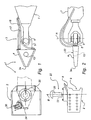
- the trailer coupling 1 shown in Figs 1-2 comprises a coupling part 2 which is adapted to be bolted or welded to a rear drawbar of a traction vehicle (not shown), and a coupling end part 3 which has a main portion 4 and a rear portion 5 and which via a joint 6 is arranged in a drawbar 7 of a trailer (not shown).
- the rear portion 4 of the coupling end part is in the joint 6 turnable about an essentially vertical axis A, and by the entire drawbar 7 being pivotally arranged at the trailer, the coupling end part 3 is positionable in an arbitrary position.
- the joint 6 can be of a type known per se.
- the coupling part 3 has a catching mouth 8 with a receiving space 9 which is adapted to receive the coupling end part 3.
- the main portion 4 of the coupling end part is illustrated in more detail in Fig. 3.
- the main portion 4 is wedge-shaped in a normal plane to the axis of rotation A of the joint 6, i.e. in a horizontal plane.
- wedge-shape is in the first place meant an essentially triangular shape of the kind as shown in the figures, but it should be noted that the main portion could also be, for example, semi-oval or have a more complicated shape.
- the main portion according to Fig. 3 is besides slightly wedge-shaped also in a vertical plane, which is evident from the fact that its lateral surfaces 10 are slightly tapering towards the front end 3a.
- the main portion 4 has two outer sectional elements 10 which are angled to each other and which in a first and a second plane are interconnected by two essentially triangular surfaces 11.
- the upper and lower edges 12a, 12b of the sectional elements extend somewhat above and below the surfaces 11.
- the main portion can be cast in one piece or consist of a plurality of parts welded together.
- the main portion is preferably at least partially hollow.
- the coupling end part 3 is further provided with a connector 14 in the form of a plurality of holes 15a-c in one of the sectional elements 10, to which electric wires and fluid lines 16, 17 are connected (see Fig. 4).
- all holes 15a-c of the connector 14 are formed on one side of the main portion 4 of the coupling end part, but of course the holes can be distributed on all sides of the main portion, including the upper and lower sides, provided that the corresponding connector in the coupling part is fitted accordingly.
- the main portion 4 is formed with a through hole 13.
- the hole can, as in the shown example, be round in cross-section and preferably tapers somewhat downwards.
- the hole 13 is positioned within the triangle that is defined by the sectional elements 10.
- a lock plunger 20 is arranged at the coupling part to be movable along a vertical axis B.
- the lock plunger 20 is preferably spring loaded inwards to the receiving space 9 and, by means of e.g. hydraulically acting actuators (not shown), movable away from the receiving space 9.
- the shape of the lock plunger is fitted to the hole 13 in the coupling end part, for instance slightly tapering.
- the lock plunger 20 constitutes, together with the hole 13, a locking mechanism 22 for securing the coupling end part 3 in the coupling part 2.
- a sensor 23 is arranged in connection with the lock plunger 20 to detect the position of the lock plunger.
- the sensor can, for instance, be an electric switch which is connected when the lock plunger takes a predetermined position, an inductive transducer or an optical sensor.
- a means 24 is arranged in the receiving space to detect whether the coupling end part 3 is fully inserted in the receiving space 9.
- This means can be a mechanical release arm or an optical or electronic transducer, for instance an inductive transducer which generates a signal when the material of the coupling end part 3 is brought into contact with the inductive transducer.
- a connector 30 is arranged at the coupling part 2 and is with the aid of an actuator 31 movable in a direction C towards a hole 34 in the wall 35 of the receiving space 9.
- the connector together with the connector 14 in the coupling end part, is included in the connecting means of the coupling for electric wires and fluid lines, such as electric cables 32 and air tubes 33.
- the connector 30 (which is shown in a perspective view in Fig. 3) comprises a plurality of contact pins 36 which are adapted to be inserted into corresponding holes 15a in the main portion 4 of the coupling end part and be brought into contact with electric contacts 40 arranged behind the holes 15a.
- the connector 30 also comprises contacts 37 to which the air tubes 33 are connected.
- the contacts 37 are provided with seals 38 so that, when they are pressed towards the hole 15b in the coupling end part 3, the contacts 37 are partly pressed into the holes while at the same time the seals 38 seal against the surrounding material. Behind the holes 15b, the air lines 17 of the trailer are connected, thereby obtaining an airtight connection between the air tubes 17 and 33.
- the connector 30 can also be provided with a slightly conical guide pin 39 which is adapted to cooperate with a hole 15c in the coupling end part.
- a protective means in the form of a flexible plate (not shown) of e.g. rubber, in which cuts corresponding to the hoels 15a have been formed.
- the plate prevents dirt and moisture from penetrating into the electric connections that are located underneath the plate while at the same time the rigid contact pins 36 can be made to pass through the plate with the aid of the actuator 31.
- the coupling end part 3 is inserted into the receiving space 9 of the coupling part 2, whereby the upper and lower edges 12a, 12b of the sectional elements 10 are brought into contact with the inner walls of the receiving space.
- the sensor 24 detects when the front end 3a of the coupling end part 3 abuts against the sensor 24, and in prior art manner the lowering of the lock plunger 20 through the hole 13 in the coupling end part 3 is effected. Consequently the trailer is mechanically secured to the traction vehicle.
- the sensor 23 detects that the lock plunger has taken its lowered position, and a signal is given to the actuator 31 which moves the connector 30 towards the coupling end part 3 inserted into the receiving space 9.
- the guide pin 39 of the connector 30 is moved into contact with the hole 15c, which ensures exact orientation of the connector 30 relative to the connector 14.
- the contact pins 36 are inserted through the holes 15a in the coupling end part and, on the other side of the holes, are brought into contact with corresponding electric contacts 40, thereby connecting the electric wires 16, 32.
- the air contacts 37 of the connector 30 are brought into contact with the holes 15b and form an airtight connection between the air tubes 17 and 33.
- the coupling end part can be designed in some other manner, as long as it is suitably positioned by being wedged into a space in the coupling part.
- the connectors for electric wires and fluid lines can be designed in other ways, as long as the operation thereof takes place separately from the mechanical connection of vehicle and trailer.
- the coupling described above can with relatively simple means be adjusted to fit on a turntable of the kind that is used when connecting a trailer to a traction vehicle.
- the most important difference is that the locking mechanism is not arranged in the same manner.
- the shape and connecting function of the coupling are essentially unchanged, with the same positive effects.
Landscapes
- Engineering & Computer Science (AREA)
- Transportation (AREA)
- Mechanical Engineering (AREA)
- Quick-Acting Or Multi-Walled Pipe Joints (AREA)
- Physical Deposition Of Substances That Are Components Of Semiconductor Devices (AREA)
- Control Of Motors That Do Not Use Commutators (AREA)
- Seal Device For Vehicle (AREA)
- Flexible Shafts (AREA)
- Mechanical Operated Clutches (AREA)
- Arrangement And Mounting Of Devices That Control Transmission Of Motive Force (AREA)
- Hydraulic Clutches, Magnetic Clutches, Fluid Clutches, And Fluid Joints (AREA)
- Medicines Containing Plant Substances (AREA)
- Fuel Cell (AREA)
- Agricultural Machines (AREA)
- Details Of Connecting Devices For Male And Female Coupling (AREA)
Claims (8)
- Anhängerkupplung zur Verbindung eines Zugfahrzeugs mit einem Anhänger, umfassend
ein an der Rückseite des Fahrzeugs montiertes Kupplungsteil (2),
ein über ein Gelenk (6) mit einer am Anhänger befestigten Zugstange (7) verbundenes Kupplungsendstück (3), wobei das Kupplungsteil (2) so beschaffen ist, das Kupplungsendstück (3) aufzunehmen, und
einen Verriegelungsmechanismus (20, 13), so beschaffen, das Kupplungsendstück (3) so am Kupplungsteil (2) festzumachen, dass die mechanische Verbindung des Fahrzeugs mit dem Anhänger gesichert ist,
wobei das Kupplungsendstück (3) einen im Wesentlichen keilförmigen Hauptabschnitt (4) und das Kupplungsteil (2) einen Aufnahmeraum (9) besitzt, der der Gestalt des Hauptabschnitts (4) angepasst ist, dadurch gekennzeichnet, dass
die Kupplung weiter getrennt betätigbare Mittel (14, 30) umfasst, um Fluidleitungen sowie elektrische Leitungen (32, 33, 16, 17) des Fahrzeugs und des Anhängers zu verbinden, wobei diese Mittel (14, 30) so angeordnet sind, dass sie nur dann betätigt werden können, um die Verbindung der elektrischen und Fluidleitungen über geeignet platzierte Löcher (34, 15a-c) im Aufnahmeraum (9) und im Hauptabschnitt (4) des Kupplungsendstückes nur dann zu bewirken, wenn das Kupplungsendstück durch den Verriegelungsmechanismus (20, 13) im Kupplungsteil mechanisch gesichert worden ist. - Kupplung nach Anspruch 1, dadurch gekennzeichnet, dass die Mittel (14, 30) zur Verbindung der Fluid- und elektrischen Leitungen erste Verbinder (30) umfassen, die am Kupplungsteil angeordnet sind und durch Löcher (15a-c) in das Kupplungsendstück eingesetzt werden können, um die Verbindung der Fluid- und elektrischen Leitungen im Zusammenwirken mit weiteren Verbindern (40) zu sichern, die im Kupplungsendstück angeordnet und hinter den benannten Löchern platziert sind.
- Kupplung nach Anspruch 2, dadurch gekennzeichnet, dass die Löcher (15a) mit Abdeckmitteln versehen sind, um die Gefahr eines Eindringens von Schmutz und Feuchtigkeit durch die Löcher zu verringern.
- Kupplung nach einem der vorangehenden Ansprüche, Mittel (24) umfassend, die in Verbindung mit dem Aufnahmeraum (9) des Kupplungsteils angeordnet sind, um zu erkennen, ob der Hauptabschnitt (4) des Kupplungsendstücks in den Aufnahmeraum (9) eingesetzt worden ist.
- Kupplung nach einem der vorangehenden Ansprüche, einen Fühler (23) umfassend, der in Verbindung mit dem Verriegelungsmechanismus (20, 13) angeordnet ist, um zu erkennen, ob die mechanische Verbindung gesichert ist, und dadurch die zeitgesteuerte Betätigung der Verbinder (14, 30) zu ermöglichen.
- Kupplung nach einem der vorangehenden Ansprüche, dadurch gekennzeichnet, dass der Hauptabschnitt (4) des Kupplungsendstücks so beschaffen ist, dass er nach Einsetzen in den Aufnahmeraum (9) mit dem Kupplungsteil (2) entlang länglicher Berührungsflächen (12a, 12b) in Berührung steht, die nur einen kleinen Teil der gesamten peripheren Oberfläche des Hauptabschnitts (4) einnehmen.
- Kupplung nach einem der vorangehenden Ansprüche, dadurch gekennzeichnet, dass der Vernegelungsmechanismus (20, 13) einen Verriegelungsdorn (20) umfasst, der in ein Loch (13) im Hauptabschnitt (4) des Kupplungsendstücks eingesetzt werden kann.
- Fahrzeug, mit einer Anhängerkupplung ausgerüstet nach einem der vorangehenden Ansprüche beansprucht.
Priority Applications (1)
| Application Number | Priority Date | Filing Date | Title |
|---|---|---|---|
| EP05110190A EP1652697B1 (de) | 2000-02-18 | 2001-02-15 | Anhängerkupplung |
Applications Claiming Priority (3)
| Application Number | Priority Date | Filing Date | Title |
|---|---|---|---|
| SE0000525 | 2000-02-18 | ||
| SE0000525A SE0000525L (sv) | 2000-02-18 | 2000-02-18 | Släpvagnskoppling |
| PCT/SE2001/000316 WO2001060645A1 (en) | 2000-02-18 | 2001-02-15 | Coupling device |
Related Child Applications (1)
| Application Number | Title | Priority Date | Filing Date |
|---|---|---|---|
| EP05110190A Division EP1652697B1 (de) | 2000-02-18 | 2001-02-15 | Anhängerkupplung |
Publications (2)
| Publication Number | Publication Date |
|---|---|
| EP1255655A1 EP1255655A1 (de) | 2002-11-13 |
| EP1255655B1 true EP1255655B1 (de) | 2005-11-02 |
Family
ID=20278493
Family Applications (2)
| Application Number | Title | Priority Date | Filing Date |
|---|---|---|---|
| EP05110190A Expired - Lifetime EP1652697B1 (de) | 2000-02-18 | 2001-02-15 | Anhängerkupplung |
| EP01904765A Expired - Lifetime EP1255655B1 (de) | 2000-02-18 | 2001-02-15 | Kupplungsvorrichtung |
Family Applications Before (1)
| Application Number | Title | Priority Date | Filing Date |
|---|---|---|---|
| EP05110190A Expired - Lifetime EP1652697B1 (de) | 2000-02-18 | 2001-02-15 | Anhängerkupplung |
Country Status (8)
| Country | Link |
|---|---|
| EP (2) | EP1652697B1 (de) |
| AT (2) | ATE308427T1 (de) |
| AU (1) | AU2001232589A1 (de) |
| DE (2) | DE60114568T2 (de) |
| DK (2) | DK1652697T3 (de) |
| ES (2) | ES2250353T3 (de) |
| SE (1) | SE0000525L (de) |
| WO (1) | WO2001060645A1 (de) |
Families Citing this family (10)
| Publication number | Priority date | Publication date | Assignee | Title |
|---|---|---|---|---|
| DE10155056B8 (de) | 2001-11-09 | 2006-06-08 | Erich Jaeger Gmbh & Co. Kg | Steckkupplungssystem zum Verbinden von Leitungen zweier Fahrzeuge |
| DE102006048778B4 (de) | 2006-10-12 | 2010-04-08 | Voith Turbo Scharfenberg Gmbh & Co. Kg | Kupplungsvorrichtung zur Kupplung von zwei Fahrzeugen |
| DE102007063248A1 (de) * | 2007-12-31 | 2009-07-02 | Volkswagen Ag | Gespann und Zugmaschine sowie Anhänger |
| DE102008014285A1 (de) | 2008-03-12 | 2009-09-17 | Jost-Werke Gmbh | Stecksysteme für Anhängerfahrzeuge |
| EP2182113A1 (de) | 2008-10-30 | 2010-05-05 | Kuraray Europe GmbH | Verfahren zum Curtain-Coating von Substraten ohne Verwendung von Tensiden |
| WO2010118420A2 (en) | 2009-04-10 | 2010-10-14 | Saf-Holland, Inc. | Automatic pneumatic/electrical coupler system for tractor-trailer combination vehicles |
| DE102010013731B4 (de) * | 2010-03-31 | 2014-09-04 | Knorr-Bremse Systeme für Nutzfahrzeuge GmbH | Anordnung zur Druckluftkopplung eines Anhängers an ein Zugfahrzeug |
| WO2012019955A1 (fr) * | 2010-08-11 | 2012-02-16 | Olivier Subrin | Système d'interconnection électromécanique. |
| EP2431201B1 (de) * | 2010-09-20 | 2014-03-12 | Voith Patent GmbH | Kupplungskopf einer Kupplungsvorrichtung zum mechanischen Verbinden von zwei Einheiten, insbesondere Fahrzeugeinheiten |
| DE102019008677B4 (de) * | 2019-12-16 | 2023-07-13 | Markus Riedlberger | Fahrzeug |
Family Cites Families (4)
| Publication number | Priority date | Publication date | Assignee | Title |
|---|---|---|---|---|
| DE849658C (de) * | 1949-10-16 | 1952-09-18 | Rockinger Johann | Anhaengerkupplung, insbesondere fuer Strassenfahrzeuge |
| DE930063C (de) * | 1953-02-13 | 1955-07-07 | Bergische Stahlindustrie | Automatische Anhaenger-Maulkupplung |
| DE2408029C2 (de) * | 1974-02-20 | 1983-06-30 | Scharfenbergkupplung Gmbh, 3320 Salzgitter | Kupplung zum selbsttätigen Verbinden zweier nach Art spurgebundener Fahrzeuge zueinander geführter Gegenstände |
| FR2656258A1 (fr) * | 1989-12-22 | 1991-06-28 | Pommier & Cie | Attelage automatique pour vehicule routier. |
-
2000
- 2000-02-18 SE SE0000525A patent/SE0000525L/ not_active IP Right Cessation
-
2001
- 2001-02-15 ES ES01904765T patent/ES2250353T3/es not_active Expired - Lifetime
- 2001-02-15 AT AT01904765T patent/ATE308427T1/de not_active IP Right Cessation
- 2001-02-15 WO PCT/SE2001/000316 patent/WO2001060645A1/en not_active Ceased
- 2001-02-15 DK DK05110190T patent/DK1652697T3/da active
- 2001-02-15 EP EP05110190A patent/EP1652697B1/de not_active Expired - Lifetime
- 2001-02-15 AU AU2001232589A patent/AU2001232589A1/en not_active Abandoned
- 2001-02-15 EP EP01904765A patent/EP1255655B1/de not_active Expired - Lifetime
- 2001-02-15 DE DE60114568T patent/DE60114568T2/de not_active Expired - Lifetime
- 2001-02-15 DK DK01904765T patent/DK1255655T3/da active
- 2001-02-15 AT AT05110190T patent/ATE381453T1/de active
- 2001-02-15 DE DE60132034T patent/DE60132034T2/de not_active Expired - Lifetime
- 2001-02-15 ES ES05110190T patent/ES2297628T3/es not_active Expired - Lifetime
Also Published As
| Publication number | Publication date |
|---|---|
| DE60132034T2 (de) | 2008-09-18 |
| DE60132034D1 (de) | 2008-01-31 |
| ATE308427T1 (de) | 2005-11-15 |
| WO2001060645A1 (en) | 2001-08-23 |
| AU2001232589A1 (en) | 2001-08-27 |
| ES2297628T3 (es) | 2008-05-01 |
| DK1652697T3 (da) | 2008-04-28 |
| EP1652697A1 (de) | 2006-05-03 |
| EP1255655A1 (de) | 2002-11-13 |
| ATE381453T1 (de) | 2008-01-15 |
| DE60114568D1 (de) | 2005-12-08 |
| DK1255655T3 (da) | 2006-02-13 |
| DE60114568T2 (de) | 2006-08-24 |
| SE514434C2 (sv) | 2001-02-26 |
| SE0000525L (sv) | 2001-02-26 |
| EP1652697B1 (de) | 2007-12-19 |
| SE0000525D0 (sv) | 2000-02-18 |
| ES2250353T3 (es) | 2006-04-16 |
Similar Documents
| Publication | Publication Date | Title |
|---|---|---|
| EP1900620B1 (de) | Steckkupplungsanordnung für einen Schlepper und einen Anhänger | |
| EP1255655B1 (de) | Kupplungsvorrichtung | |
| US11419256B2 (en) | Coupling plate | |
| US20220332158A1 (en) | Automated connection between towing vehicle and trailer | |
| CN101432156B (zh) | 用于连接供给管线的连接系统 | |
| KR0160596B1 (ko) | 레일 차량용 자동 분리기 | |
| US20120201598A1 (en) | Coupler | |
| US4156551A (en) | Device for automatically connecting and disconnecting pipings and wirings between rolling stocks | |
| US11805718B2 (en) | Docking apparatus having a docking receptacle and a docking insert, and method for coupling a vehicle | |
| AU2011218642A1 (en) | Coupler head of a coupling device for mechanically connecting two units, particularly vehicle units | |
| CN116710351B (zh) | 自动牵引车拖车联接器 | |
| EP0902505A3 (de) | Abgedichteter elektrischer und/oder optischer Steckverbinder | |
| EP1016340A3 (de) | Automatische Mehrzweckkupplungsvorrichtung für landwirtschaftliche Geräte oder dergleichen | |
| SE464450B (sv) | Slaepvagnskoppling | |
| US6390490B1 (en) | Quick connect tractor hitch coupling | |
| AU2011101527A4 (en) | A Coupler | |
| ES2317156T3 (es) | Acoplamiento multifuncional. | |
| JP4424999B2 (ja) | 接続装置 | |
| CN115707195A (zh) | 部件搭载装置以及台车 | |
| CA3212121A1 (en) | Automated connection between towing vehicle and trailer | |
| AU2013211543C1 (en) | A Coupler | |
| CN120936501A (zh) | 用于连接牵引车与鞍式挂车之间的管路的耦联方法和系统 | |
| BR102023017422A2 (pt) | Dispositivo de acoplamento para um veículo de tração com um meio de detecção de objetos acoplado a ele | |
| CN116648396A (zh) | 列车联接件适配器和用于将列车联接件适配器安装在轨道车辆的联接件上的方法 | |
| JP2010086856A (ja) | コネクタ接続構造 |
Legal Events
| Date | Code | Title | Description |
|---|---|---|---|
| PUAI | Public reference made under article 153(3) epc to a published international application that has entered the european phase |
Free format text: ORIGINAL CODE: 0009012 |
|
| 17P | Request for examination filed |
Effective date: 20020525 |
|
| AK | Designated contracting states |
Kind code of ref document: A1 Designated state(s): AT BE CH CY DE DK ES FI FR GB GR IE IT LI LU MC NL PT SE TR |
|
| AX | Request for extension of the european patent |
Free format text: AL;LT;LV;MK;RO;SI |
|
| 17Q | First examination report despatched |
Effective date: 20041104 |
|
| GRAP | Despatch of communication of intention to grant a patent |
Free format text: ORIGINAL CODE: EPIDOSNIGR1 |
|
| GRAS | Grant fee paid |
Free format text: ORIGINAL CODE: EPIDOSNIGR3 |
|
| GRAA | (expected) grant |
Free format text: ORIGINAL CODE: 0009210 |
|
| AK | Designated contracting states |
Kind code of ref document: B1 Designated state(s): AT BE CH CY DE DK ES FI FR GB GR IE IT LI LU MC NL PT SE TR |
|
| PG25 | Lapsed in a contracting state [announced via postgrant information from national office to epo] |
Ref country code: LI Free format text: LAPSE BECAUSE OF FAILURE TO SUBMIT A TRANSLATION OF THE DESCRIPTION OR TO PAY THE FEE WITHIN THE PRESCRIBED TIME-LIMIT Effective date: 20051102 Ref country code: CH Free format text: LAPSE BECAUSE OF FAILURE TO SUBMIT A TRANSLATION OF THE DESCRIPTION OR TO PAY THE FEE WITHIN THE PRESCRIBED TIME-LIMIT Effective date: 20051102 Ref country code: AT Free format text: LAPSE BECAUSE OF FAILURE TO SUBMIT A TRANSLATION OF THE DESCRIPTION OR TO PAY THE FEE WITHIN THE PRESCRIBED TIME-LIMIT Effective date: 20051102 Ref country code: BE Free format text: LAPSE BECAUSE OF FAILURE TO SUBMIT A TRANSLATION OF THE DESCRIPTION OR TO PAY THE FEE WITHIN THE PRESCRIBED TIME-LIMIT Effective date: 20051102 |
|
| REG | Reference to a national code |
Ref country code: GB Ref legal event code: FG4D |
|
| REG | Reference to a national code |
Ref country code: CH Ref legal event code: EP |
|
| REF | Corresponds to: |
Ref document number: 60114568 Country of ref document: DE Date of ref document: 20051208 Kind code of ref document: P |
|
| PG25 | Lapsed in a contracting state [announced via postgrant information from national office to epo] |
Ref country code: SE Free format text: LAPSE BECAUSE OF FAILURE TO SUBMIT A TRANSLATION OF THE DESCRIPTION OR TO PAY THE FEE WITHIN THE PRESCRIBED TIME-LIMIT Effective date: 20060202 Ref country code: GR Free format text: LAPSE BECAUSE OF FAILURE TO SUBMIT A TRANSLATION OF THE DESCRIPTION OR TO PAY THE FEE WITHIN THE PRESCRIBED TIME-LIMIT Effective date: 20060202 |
|
| REG | Reference to a national code |
Ref country code: DK Ref legal event code: T3 |
|
| PG25 | Lapsed in a contracting state [announced via postgrant information from national office to epo] |
Ref country code: IE Free format text: LAPSE BECAUSE OF NON-PAYMENT OF DUE FEES Effective date: 20060215 |
|
| PG25 | Lapsed in a contracting state [announced via postgrant information from national office to epo] |
Ref country code: MC Free format text: LAPSE BECAUSE OF NON-PAYMENT OF DUE FEES Effective date: 20060228 Ref country code: LU Free format text: LAPSE BECAUSE OF NON-PAYMENT OF DUE FEES Effective date: 20060228 |
|
| PG25 | Lapsed in a contracting state [announced via postgrant information from national office to epo] |
Ref country code: PT Free format text: LAPSE BECAUSE OF FAILURE TO SUBMIT A TRANSLATION OF THE DESCRIPTION OR TO PAY THE FEE WITHIN THE PRESCRIBED TIME-LIMIT Effective date: 20060403 |
|
| REG | Reference to a national code |
Ref country code: ES Ref legal event code: FG2A Ref document number: 2250353 Country of ref document: ES Kind code of ref document: T3 |
|
| REG | Reference to a national code |
Ref country code: CH Ref legal event code: PL |
|
| ET | Fr: translation filed | ||
| PLBE | No opposition filed within time limit |
Free format text: ORIGINAL CODE: 0009261 |
|
| STAA | Information on the status of an ep patent application or granted ep patent |
Free format text: STATUS: NO OPPOSITION FILED WITHIN TIME LIMIT |
|
| 26N | No opposition filed |
Effective date: 20060803 |
|
| REG | Reference to a national code |
Ref country code: IE Ref legal event code: MM4A |
|
| PG25 | Lapsed in a contracting state [announced via postgrant information from national office to epo] |
Ref country code: TR Free format text: LAPSE BECAUSE OF FAILURE TO SUBMIT A TRANSLATION OF THE DESCRIPTION OR TO PAY THE FEE WITHIN THE PRESCRIBED TIME-LIMIT Effective date: 20051102 |
|
| PG25 | Lapsed in a contracting state [announced via postgrant information from national office to epo] |
Ref country code: CY Free format text: LAPSE BECAUSE OF FAILURE TO SUBMIT A TRANSLATION OF THE DESCRIPTION OR TO PAY THE FEE WITHIN THE PRESCRIBED TIME-LIMIT Effective date: 20051102 |
|
| REG | Reference to a national code |
Ref country code: FR Ref legal event code: PLFP Year of fee payment: 16 |
|
| REG | Reference to a national code |
Ref country code: FR Ref legal event code: PLFP Year of fee payment: 17 |
|
| REG | Reference to a national code |
Ref country code: FR Ref legal event code: PLFP Year of fee payment: 18 |
|
| PGFP | Annual fee paid to national office [announced via postgrant information from national office to epo] |
Ref country code: DK Payment date: 20200116 Year of fee payment: 20 Ref country code: FI Payment date: 20200115 Year of fee payment: 20 Ref country code: NL Payment date: 20200227 Year of fee payment: 20 Ref country code: IT Payment date: 20200121 Year of fee payment: 20 Ref country code: GB Payment date: 20200116 Year of fee payment: 20 Ref country code: DE Payment date: 20200115 Year of fee payment: 20 Ref country code: ES Payment date: 20200302 Year of fee payment: 20 |
|
| PGFP | Annual fee paid to national office [announced via postgrant information from national office to epo] |
Ref country code: FR Payment date: 20200116 Year of fee payment: 20 |
|
| REG | Reference to a national code |
Ref country code: DE Ref legal event code: R071 Ref document number: 60114568 Country of ref document: DE |
|
| REG | Reference to a national code |
Ref country code: NL Ref legal event code: MK Effective date: 20210214 |
|
| REG | Reference to a national code |
Ref country code: DK Ref legal event code: EUP Expiry date: 20210215 |
|
| REG | Reference to a national code |
Ref country code: GB Ref legal event code: PE20 Expiry date: 20210214 |
|
| REG | Reference to a national code |
Ref country code: FI Ref legal event code: MAE |
|
| PG25 | Lapsed in a contracting state [announced via postgrant information from national office to epo] |
Ref country code: GB Free format text: LAPSE BECAUSE OF EXPIRATION OF PROTECTION Effective date: 20210214 |
|
| REG | Reference to a national code |
Ref country code: ES Ref legal event code: FD2A Effective date: 20210730 |
|
| PG25 | Lapsed in a contracting state [announced via postgrant information from national office to epo] |
Ref country code: ES Free format text: LAPSE BECAUSE OF EXPIRATION OF PROTECTION Effective date: 20210216 |