EP1256929A2 - Vorrichtung zur Tonerzeugung und Gebrauch davon durch ein elektronisches Musikinstrument - Google Patents
Vorrichtung zur Tonerzeugung und Gebrauch davon durch ein elektronisches Musikinstrument Download PDFInfo
- Publication number
- EP1256929A2 EP1256929A2 EP02010401A EP02010401A EP1256929A2 EP 1256929 A2 EP1256929 A2 EP 1256929A2 EP 02010401 A EP02010401 A EP 02010401A EP 02010401 A EP02010401 A EP 02010401A EP 1256929 A2 EP1256929 A2 EP 1256929A2
- Authority
- EP
- European Patent Office
- Prior art keywords
- main lever
- tone
- lever
- tone generation
- quick
- Prior art date
- Legal status (The legal status is an assumption and is not a legal conclusion. Google has not performed a legal analysis and makes no representation as to the accuracy of the status listed.)
- Withdrawn
Links
Images



Classifications
-
- G—PHYSICS
- G10—MUSICAL INSTRUMENTS; ACOUSTICS
- G10H—ELECTROPHONIC MUSICAL INSTRUMENTS; INSTRUMENTS IN WHICH THE TONES ARE GENERATED BY ELECTROMECHANICAL MEANS OR ELECTRONIC GENERATORS, OR IN WHICH THE TONES ARE SYNTHESISED FROM A DATA STORE
- G10H1/00—Details of electrophonic musical instruments
- G10H1/32—Constructional details
- G10H1/34—Switch arrangements, e.g. keyboards or mechanical switches specially adapted for electrophonic musical instruments
- G10H1/342—Switch arrangements, e.g. keyboards or mechanical switches specially adapted for electrophonic musical instruments for guitar-like instruments with or without strings and with a neck on which switches or string-fret contacts are used to detect the notes being played
-
- G—PHYSICS
- G10—MUSICAL INSTRUMENTS; ACOUSTICS
- G10H—ELECTROPHONIC MUSICAL INSTRUMENTS; INSTRUMENTS IN WHICH THE TONES ARE GENERATED BY ELECTROMECHANICAL MEANS OR ELECTRONIC GENERATORS, OR IN WHICH THE TONES ARE SYNTHESISED FROM A DATA STORE
- G10H1/00—Details of electrophonic musical instruments
- G10H1/32—Constructional details
Definitions
- the present invention relates to a tone generation operating device that is close to strings in the basic execution but enables a player to show every kind of musical expression with his bare hands without using a bow, a pick, a plectrum and so forth and an electronic musical instrument using the tone generation operating device.
- an electronic keyboard musical instrument called a synthesizer is not without resemblance to the electronic musical instrument according to the present invention.
- Fig. 17 depicts the general configuration of a conventional electronic keyboard instrument.
- the conventional keyboard instrument comprises: a keyboard 11; a tone source 12 that is driven by a signal from a switch indicating the tone selected on the keyboard 11 to generate an electrical signal of a frequency corresponding to the selected tone; and a loudspeaker system 15 composed of an amplifier 13 for amplifying the electric signal generated by the tone source 2 and a loudspeaker 14.
- the tone source 12 has connected thereto various registers 12A and a sound effecter 12B.
- the registers 12A are those for setting, for example, the tone of one of musical instruments in which the electronic keyboard is desired to be played, for setting the attack speed of the tone, the loudness during attack and the decay speed, and for setting timbre.
- the sound effecter 12B has a facility of imparting a pitch bend to the tone being generated or a facility of repeatedly changing the tone volume.
- the attack speed of tone, the loudness during the attack time, the decay speed, and so forth are preset in the registers 12A as mentioned above--this makes it impossible for a player to freely select the attack speed, the tone amplitude during the attack time and the decay speed by changing the key depressing operations. That is, the conventional electronic keyboard instrument is defective in that the player cannot fully express his emotion, as is well-known in the art.
- One of such proposals is to detect the speed of depression of each key on the keyboard 11 and control the tone volume during attack in accordance with the detected speed. That is, there is proposed an electronic keyboard instrument of the type wherein the stronger (the more quickly) the key is depressed, the more the amplitude of the tone being generated increases, providing increased volume.
- the conventional electronic keyboard instrument has such defects as listed below.
- the electronic musical instrument according to the present invention comprises:
- the tone generation operating device comprises:
- the most striking feature of the electronic musical instrument according to the present invention resides in the construction in which the tone selector for selecting the tone desired to generate and the tone generation operating device for generating the tone selected by the tone selector are provided independently of each other. That is, the electronic musical instrument according to the present invention is designed so that a player performs the tone selecting operation with one hand and the tone generating operation with the other hand. With this arrangement, whether to generate the tone selected by the tone selector can be controlled by the tone generation operating device that is manipulated with the other hand. Accordingly, legato or slur performance can easily be done, for example, by changing the tone on the part of the tone selector while keeping the tone generation operating device in its tone-generating state.
- the tone selector and the tone generation operating device are manipulated separately of each other, the tone generating operation can be performed independently of the tone selecting operation.
- Reference numeral 100 denotes a tone selector that decides the tone desired to generate
- 200 denotes a tone generation operating device that generates a tone generation control signal for controlling whether to generate the desired tone, the volume (amplitude) of the desired tone during the attack time, the sustain time of the tone, the decay speed of the tone, and so forth
- 300 denotes a signal source that generates a tone source signal containing the pitch frequency corresponding to the tone selected by the tone selector 100
- 400 denotes a tone generation control circuit that effects interrupting control and/or amplitude control of the tone source signal from the signal source 300 by the tone generation control signal from the tone generation operating device 200 to generate a tone signal
- 500 denotes a loudspeaker unit composed of an amplifier 501 and a loudspeaker 502.
- the tone generation control circuit 400 can be formed by multiplying means that multiplies the tone source signal from the signal source 300 and the tone control signal from the tone generation operating device 200. Concretely, it can be formed using a variable gain controlled amplifier VCA.
- the present invention features that the tone selector 100 and the tone generation operating device 200 are provided independently of each other as depicted in Fig. 1. This structural feature produces entirely new working-effects as will become apparent from the embodiments described below.
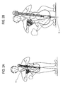
- Figs. 2A and 2B show appearances of electronic instruments according to the present invention.
- Depicted in Fig. 2A is a relatively small, alto- or soprano-type electronic musical instrument.
- a player carries the instrument slung over his neck with a belt 5 so that he can play while walking.
- Fig. 2B Shown in Fig. 2B is a relatively large electronic musical instrument, whose weight is supported by a support rod 6. In this case, the player sits playing the instrument.
- Fig. 3 illustrates the general construction of the electronic musical instrument according to the present invention.
- Reference numeral 17 denotes an instrument body, which is shown to be similar to that of an ordinary stringed instrument but need not always be so.
- a fingerboard 18 Extended from the body 12 is a fingerboard 18, which may be of the same construction as that part of an ordinary stringed instrument which is called a neck.
- the tone selector 100 is mounted on the fingerboard 18.
- the tone selector 100 is made up of conductive strings 101 and conductive frets 102 arranged on the fingerboard 18.
- Reference numeral 19 denotes a lever pivotally secured at one end to the body 17 about a pivot pin 19A.
- the lever 19 carries at the other end the tone generation operating device 200 shown in Fig. 1.
- the pivot pin 19A there are provided variable resistors for volume control and for pitch bend use and for timbre control. These variable resistors are each actuated in accordance with the angle of rotation of the lever 19 as will be described later on.
- the tone selector 100 is composed of the conductive strings 101 and the conductive frets 102 as referred to above.
- the number of conductive strings 101 is selected in the range of four to six according to the character of the musical instrument. That is, six, four strings are used for a musical instrument of the guitar family, four for the violin family, and three for a samisen or three-stringed Japanese banjo.
- Fig. 3 shows the case where the musical instrument of the violin family is assumed, with four strings.
- the conductive strings 101 are selectively pressed against one of the conductive frets 102 to establish electric connections between them, and the tone is selected according to which of the strings 101 is pressed into contact with which of the frets 102. Accordingly, the conductive strings 101 need not be stretched with a tensile strength high enough to resonate at predetermined frequencies as in ordinary musical instruments.
- Fig. 4 depicts another example of the tone selector 100, in which membrane switches 103 (switches formed by placing contacts between laminated sheets) are arranged in matrix form so that they are pressed to select a tone.
- Fig. 5 shows still another example of the tone selector 100, in which a resistance layer 104 is coated all over the front surface of the fingerboard 18, an insulating sheet 106 is disposed opposite the resistance layer 104 and thin, streak-like conductive layers 105 are formed on the back of the insulating sheet 106 in opposing relation to the respective strings 101. By pressing the insulating sheet 106 to bring the conductive layer 105 into contact with the resistance layer 104, a voltage signal corresponding to the position of contact therebetween is derived from the resistance layer 105 to select a tone.
- the tone is selected by a method similar to that used for ordinary stringed instruments--this enables the player to play the instrument without a sense of incongruity. While in the Fig. 3 embodiment the loudspeaker unit 500 (see Fig. 1) is built in the instrument body 17, it will easily be understood that the incorporation of the loudspeaker unit 500 in the body 17 is not essential to the present invention.
- the signal source 300 and the tone generation control circuit 400 shown in Fig. 1 may also be optionally built in the body 17 or provided separately thereof.
- Figs. 6 to 8 the configuration of the tone generation operating device 200 will be described.
- reference numeral 21 denotes a cover of the tone generation operating device 200; 22 denotes base for supporting respective elements of the tone generation operating device 200; 23 denotes a main lever that is a principal part of the tone generation operating device 200; and 24 denotes a quick lever characteristic of the present invention.
- the main lever 23 is formed by a plate-like member substantially rectangular in plane configuration, which is coupled at one end to the base 22 through a plate spring 231 so that the other end portion of the main lever 23 is pretensioned upward by the biasing force of the plate spring 22.
- the upward tension is received by a pad 226 (Fig. 7) mounted on the underside of the base 22 and an end plate 232a of an inverted T-section lever stopper 232 secured to the underside of the main lever 23 and extended downward through a through hole 22H made in the base 22, by which the main lever is held in a predetermined position.
- the pad 226 is formed by a cushion material attached to a plate spring 225 that supports a strain sensor 227 or shock sensor 227' described later on--this is intended to prevent the lever stopper 232 from making direct contact with the plate spring 225. Further, a pad 226 of a cushion material is also interposed between the plate spring 225 and the base 22 to prevent the plate spring 225 from making direct contact with the base 22.
- the end plate 232a of the lever stopper 232 is extended to the side opposite the pad 226 to form an actuator of a first sensor 223 mounted on the underside of the base 22.
- the first sensor 223 is formed by an optical distance measuring device (a photo interrupter) composed of a light emitting element and a light receiving element.
- the first sensor 223 measures the time from the instant the light emitted from the light emitting element is reflected by the end plate 232a of the lever stopper 232 to the instant the reflected light reaches the light receiving element, and generates a voltage signal of a value proportional to the amount of depression of the main lever 23.
- Reference numeral 221 denotes a cushion made of rubber which receives the main lever 23 when it is depressed.
- Reference numeral 228 denotes a speed sensor for sensing the speed of depression of the main lever 23, which has a normally closed contact and a normally open contact. Upon depression of the main lever 23, the normally closed contact turns OFF (open) and then the normally open contact turns OFF (closed); the speed sensor 228 measures the time from the timing of generation of the OFF signal to the timing of generation of the ON signal and outputs a voltage corresponding to the time length thus measured.
- a first touch sensor 234 which is an electrode formed by a conductive plate or plated layer of a conductive material. The instant a finger of the player touches the conductive layer, the touch sensor 234 senses a change in noise by the player or in the electrostatic capacity of the main lever 23, thereby detecting the contact of the player's finger with the main lever 23.
- the second touch sensor 229 may also be an electrode formed by a conductive plate or plated layer of a conductive material.
- the second touch sensor 229 senses the contact therewith of the player's finger by, for example, an increase in noise or a change in the electrostatic capacity of the sensor 229 itself, and measures the time from the instant the player's finger moves off the first touch sensor 234 to the instant the finger touches the second touch sensor 229, generating a voltage signal of a value that is in inverse proportion to the time measured.
- the value of the voltage signal increases with a decrease in the time during which the player's finger moves from the first touch sensor 234 to the second touch sensor 229. Since the speed sensor 228 and the first sensor 223 are well known, no further description will be given of their construction.
- the quick levers 24A and 24B are each made smaller than the main lever 23 and lightweight so that they can respond to high-sped playing operations.
- the quick levers 24A and 24B have their rear end portions secured to one end portion of a plate spring 241, which has its other end portion is secured to the rear end portion of the main lever with a spacer 242 interposed therebetween so that the quick levers 24A and 24B are held above the top of the main lever 23 with their free end portions upwardly raised by the spring force of the plate spring 241.
- an L-section lever stopper 243 which projects downwardly from the underside of the free end of each of the quick levers 24A and 24B and passes through a through hole 23H bored through the main lever 23, abuts against and hence is stopped by a stopper 245 mounted on the underside of the main lever 23 (Fig. 7), by which each of the quick levers 24A and 24B is positioned at a standstill.
- Reference numeral 244 denotes a pad formed by a cushion material on the top of the main lever 23, for receiving each of the quick levers 24A and 24B when it is pressed.
- a second sensor 246 is mounted on the underside of the main lever 23 in opposing relation to the bend of the L-shaped lever stopper 243.
- the second sensor 246 can also be formed by an optical distance measuring device (a photo interrupter), which generates a voltage signal proportional to the amount of depression of each of the quick levers 24A and 24B.
- the main lever 23 features a raised rib or ridge 233 provided on its operating surface (on which the first touch sensor 234 is provided) substantially centrally thereof in its widthwise direction.
- the operating surface of the main lever 23 is gradually sloped or raised from its both longer marginal edges towards the center of the operating surface in its widthwise direction to form the ridge 233.
- Plural main levers 23 each having the ridge 233 are arranged side by side, by which plural sawtooth projections and depressions can be formed in the direction of arrangement of the main levers 23. By sliding player's fingers in the direction of arrangement of the projections and depressions, the player can press the man levers 23 in his desired order. This allows ease in playing arpeggio.
- each of the quick levers 24A and 24B there are formed plural projections and depressions arranged lengthwise thereof. These projections and depressions may preferably be formed sawtooth--this enhances operability.
- the quick levers 24A and 24B can be moved up and down at high speed. Accordingly, the same tone can easily be generated repeatedly. Further, by alternately actuating the two quick levers 24A and 24B with two fingers (through utilization of the projections and depressions), the same tone can be repeatedly generated at so high a speed as not to be achievable with conventional keyboard musical instruments.
- Fig. 8 shows the external structure of an example of the tone generation operating device 200 provided with four sets of the main lever 23 and the quick levers 24A and 24B.
- Fig. 9 illustrates the electrical circuitry of the afore-mentioned four-channel type electronic musical instrument.
- the tone selectors 100 for example, voltage-controlled oscillators, which form signal sources 310A, 310B, 310C and 310D, each generate a tone source signal containing a pitch frequency corresponding to the selected tone.
- a signal of a tone corresponding to an open string is generated.
- a control signal from the tone selector 100, for determining each tone is applied to the signal source 300 and converted by, for example, a voltage-controlled oscillator VCO forming the signal source 300, into a tone source signal of a desired timbre containing the pitch frequency of the tone selected by the tone selector 100.
- the tone source signal generated by the signal source 300 is input to a signal input terminal of, for example, a variable gain controlled amplifier VCA forming the tone generation control circuit 400.
- a tone generation control signal from the tone generation operating device 200 is input to a gain control terminal of each variable gain controlled amplifier VCA, wherein the tone source signal is gain-controlled (multiplied) by the tone generation control signal to generate a tone or musical signal.
- the tone generation control circuit 400 does not output the tone source signal unless the tone generation control signal is input thereto from the tone generation operating device 200; namely, a tone is generated only when the main lever 23 or quick levers24A and 24B forming the tone generation operating device 200 are pressed.
- This tone generation control will hereinafter be referred to as first tone generation control.
- the string 101, which forms each tone selector 100, and the main lever 23, which forms each tone generation operating device 200, are operatively associated with one of the channels.
- the main lever 23 or quick levers 24A and 24B of the same channel as the string of the selected string it is possible to generate the selected tone.
- reference numeral 900 denotes an output control unit.
- the output control unit 900 mixes tone signals output from the variable gain controlled amplifiers VCA forming the tone generation control circuits 400, and provides the mixed signal to the loudspeaker unit 500.
- Variable resistors 601, 602 and 603 provided on the lever 10 at its pivotal mounting point 9A as referred to previously with reference to Fig. 3 are connected to the output control unit 100. By actuating these variable resistors 601, 602 and 603 in accordance with the angle of rotation of the lever 19, it is possible to produce effects such as control of the level of the signal to be sent to the loudspeaker unit 500, shifting its frequency to conduct pitch-bend performance and timbre control.
- variable resistors 601, 602 and 603 can each be actuated in distinction from the others as described below.
- first tone generation control When turning the lever 19 in parallel to the body 17 without applying any force to the lever 19 in the thickwise direction of the body 17, only the variable resistor 601 is driven to effect volume control.
- the lever 19 When the lever 19 is turned while being somewhat pressed forwardly of the player, only the variable resistor 602 for pitch bend use is driven.
- the lever 19 is turned while being pressed more forward, only the variable resistor 603 for timbre control is driven.
- Such sound effect control by the lever 19 will hereinafter be referred to as second tone generation control.
- the sensors for sensing the amount of operation are not limited specifically to the variable resistors 601, 602 and 603 shown in Fig. 9 but may be sensors for sending the speed of rotation, angular velocity or acceleration of the lever 19. Output signals from these variable resistors are used to effect control for crescendo, descrescendo, sforzando, bright, mellow and the like, thereby achieving richly expressive performance.
- the quick levers 24A and 24B are mounted on the main lever 23, it is possible to play a quick passage with a low sound.
- Fig. 10 depicts a circuit configuration for achieving the performance.
- a tone source signal SA-1 (Fig. 11A) of a fixed amplitude, which contains the pitch frequency specified by the operation of the tone selector 200, is output from a voltage-controlled oscillator VCO operating as the signal source 300, and the tone source signal SA-1 of the fixed amplitude is applied, for example, to a signal input terminal of a variable gain controlled amplifier VCA acting as the tone generation control circuit 400.
- the quick lever 24 is used. Even if one quick lever is repeatedly manipulated with the same finger (refer to the arrow A in Fig. 7), it quickly responds, permitting performance of a quick passage.
- the output signal from the tone generation operating device 200 is a multiplied output SD-1 (see Fig. 11D) from a multiplier 250 by which an output signal SB-1 (see Fig. 11B) from the second sensor 246 having detected the amount of depression of the quick lever 24 is multiplied by an output signal SC-1 (see Fig. 11C) from the first sensor 223 having detected the amount of depression of the main lever 23. Accordingly, the amplitude of the multiplied output signal SD-1 is in proportion as well to the force having depressed the main lever 23.
- the quick lever 24 can be manipulated at high speed with a small amount of force.
- the quick lever 24 is pressed with a small amount of force, the amount of depression of the main lever 23 can be made very small.
- the amplitude of the multiplied output signal SD-1 from the amplifier 250 decreases accordingly.
- the multiplied output signal DS-1 sa a tone generation control signal to the tone generation control circuit 400, the amplitude of its output tone source signal SE-1 (see Fig. 11E) also decreases. Accordingly, a quick passage can be played pianissimo.
- the quick lever 24 is pressed increasingly harder, the main lever 23 is also depressed increasingly deeper and the amplitude of the multiplied output signal SD-1 also gradually larger, permitting richly expressive performance.
- tone sources corresponding to respective tones are provided, and a signal from the selected tone signal source is given a tone-generation waveform envelope specific to the selected musical instrument.
- a signal from the selected tone signal source is given a tone-generation waveform envelope specific to the selected musical instrument.
- Fig. 12 shows the circuit configuration for playing slur and legato.
- the selected tone be that corresponding to the channel of the tone selector 100.
- the first touch sensor 234 senses the contact therewith of the main lever 23 and the sensed signal SF-2 is provided to a multiplier 251.
- a signal SC-2 proportional to the amount of depression of the main lever 23 is provided from the first touch sensor 234 to the multiplier 251, from which a multiplied signal SD-2 of the signals SC-2 and SF-2 is output as a tone generation control signal from the tone generation operating device 200.
- the tone generation control circuit 400 outputs the signal fed from the tone source (VCO) with an amplitude corresponding to the amount of depression of the main lever 23.
- Fig. 13 shows the circuit configuration for playing detache.
- the output signal from the speed sensor 228, which senses the speed of depression of the main lever 23 is input to an envelope generator 252, from which is provided a tone generation waveform envelope signal of an attack amplitude proportional to the speed of the depression of the main lever 23. That is, the speed sensor 228 outputs a voltage signal of the amplitude proportional to the speed of depression of the main lever 23 or the corresponding digital value, and the envelope generator 252 outputs a tone generation waveform envelope signal that has an attack amplitude (amplitude during attack) proportional to the value of the input signal to the envelope generator 252.
- the tone generation waveform envelope is specific to each musical instrument and is generally expressed by attack, decay, sustain and release portions that continue on the time axis. After the attack the envelope varies in accordance with characteristics preset in the envelope generator 252.
- the output signal from the first touch sensor 234 goes zero, and consequently, the output signal from the tone generation operating device 200 abruptly goes zero at that time even if the envelope generator 252 is outputting an envelope waveform.
- the output signal from the tone generation control circuit 400 turns OFF. That is, since the tone can be silenced by moving the player's finger off the first touch sensor 234 of the main lever 23, it is possible to play detache.
- the first sensor 223 provides a voltage signal proportional to the amount of the depression of the main lever 23.
- the second sensor 246 also produces an output signal.
- the multiplier 250 multiples the both the output signals from the both sensors and provides the multiplied output signal SD-1, which is applied to the tone generation control circuit 400 to control it, outputting therefhrough the tone source signal from the VCO 300 corresponding to the tone selected by the tone selector 100.
- the grace and trill that can be played in this case are the grace and trill of the same speed and of the same quality as those played by the actual wind and stringed instruments.
- the output signal from the first touch sensor 234 is a "0" or "1" logic signal, by which the multiplier 251 is ON-OFF controlled to permit or inhibit the passage therethrough of the signal from the first sensor 223 that has sensed the amount of depression of the main lever 23.
- Fig. 14 shows the circuit configuration for effecting control during the lever OFF duration.
- the envelope generator 227, the multiplier 253, an inverting amplifier 254, the strain sensor 227 and the speed sensor 228 are used.
- free end of the plate spring 225 fixed at one end to the base 22 is at a distance from the pad 224 on the base 22.
- the spring force of the spring 231 overcomes the spring force of the plate spring 225, allowing the plate spring 225 to be pressed against the pad 224 by the end plate 232a.
- the plate-like strain sensor 227 is passed on a gently curved portion adjacent the fixed end portion of the plate spring 225. With the plate spring 225 pressed against the pad 224, the internal strain of the strain sensor 227 is at a maximum, and consequently, its output voltage is also at a maximum. When the main lever 23 is pressed and the plate spring 225 is released from the pressure toward the pad 224, the internal strain of the strain sensor 227 is at a minimum and its output voltage is also minimized.
- the output voltage from the strain sensor 227 is at a maximum, and a difference voltage ⁇ S between the output voltage and a reference voltage E is detected by the inverting amplifier 255 and applied to the multiplier 253.
- the reference voltage E is preset so that the difference voltage ⁇ S becomes approximately zero.
- the output voltage from the strain sensor 227 is attenuated by the depression of the main lever 23, while at the same time the output voltage ⁇ S from the inverting amplifier 255 becomes maximized.
- the multiplier 253 calculates the product of the voltage ⁇ S and the envelope, and outputs the multiplied output.
- the plate spring 225 is pressed by the end plate 232a and the strain increases; as a result, the difference voltage ⁇ S attenuates down to its minimum value and the multiplier outputs also attenuates accordingly. That is, the tone silence operation is carried out. Since attenuation speed of the output voltage from the strain sensor 227 depends on the strain attenuation speed of the strain sensor 227, the tone silencing operation can be performed quickly or slowly by releasing the main lever 23 quickly or slowly.
- Fig. 15 shows the circuit configuration for this purpose.
- the outputs from two second sensors 246A and 246B which sense the amounts of depression of the main lever 23 and the two quick levers 24A and 24B, are added together by an adder 245, and the added output is applied to the multiplier 253.
- To the other input terminal of the multiplier 253 is provided the output from the first sensor that senses the amount of depression of the main lever 23.
- Fig. 15 circuitry and utilizes the projections and depressions formed in the surface of the quick lever 24.
- the quick lever 24 moves up and down as the finger slides on the projections and depressions.
- the speed of repeating the up and down movements of the quick lever 24 can be controlled by the finger sliding speed; high-speed ON-OFF signals can be generated by quickly sliding the finger.
- the same tone can be generated repeatedly at ultra-high speed. This speed is quite impossible to realize in the prior art.
- Fig. 16 shows the circuit configuration necessary for percussive performance.
- the first touch sensor 234, the impact sensor 224' and the second touch sensor 229 are used.
- the output signal from the first touch sensor 234 is polarity inverted by an inverter 255', from which the inverted signal is input to the one input terminal of the multiplier 253.
- the output signal from the impact sensor 227' is applied to the envelope generator 256, whose output is provided to the other input terminal of the multiplier 253.
- the output signal from the second touch sensor 229 is provided via an inverter 257 to the one input terminal of a multiplier 258, which is supplied at its other input terminal with the output signal from the multiplier 253.
- the multiplier 253 is held closed by the inverter 255, and when the finger is slipped away from the first touch sensor 234 at the free end of the main lever 23, an output is derived from the impact sensor 227' by the return motion of the main lever 23, and the envelope generator 256 responds to the output from the impact sensor 257' to generate the tone generation waveform envelope corresponding to the desired musical instrument, the envelope being provided to the multiplier 253.
- the inverter 255' outputs a "1," which is applied to the multiplier 253 to hold it open. Accordingly, the signal from the envelope generator 256 passes intact through the multiplier 253 and is input to the multiplier 258.
- the second touch sensor 229 is placed on the base 22 just at the position where it is hit by the player's finger slipped away from the main lever 23 in the direction of the arrow C in Figs. 6 and 7. Accordingly, until the finger comes into touch with the second touch sensor 229 after slipping away from the main lever 23, the second touch sensor 229 outputs a "0" signal and the multiplier 258 is held open by the output "1" from the inverter 257. Accordingly, the output signal from the envelope generator 256 is applied intact to the signal source (VC) 300 to generate a tone.
- VC signal source
- the output from the second touch sensor 229 goes to "1" at the instant the finger comes into contact with the second touch sensor 229, the output from the multiplier 258 is cut off in the course of attenuation by the output "0"from the inverter 257. That is, the tone is damped out during attenuation. Accordingly, it is possible to achieve various damping of the tone during attenuation by changing the way of controlling the second touch sensor 229.
- the present invention is not limited specifically to the performances and effects described above but may be applied as well to other basic performances and effects such as sostenute, convergenceo, crescendo and decrescendo. While in the above embodiments the signal source 300, the tone generation control circuit 400 and the loudspeaker unit 500 are all built in the body 17, they may be displaced outside the body 17. In this instance, the electronic musical instrument needs only to be equipped with the tone selector 100 and the tone generation operating device 200. With such an arrangement, it is possible to play the electronic musical instrument by use of the existing tone source unit for conventional electronic musical instruments.
- the small quick levers 24A and 24B are provided above one main lever 23, it is also possible to provide medium-sized lever above the main lever 23 and a small quick lever above the medium-sized lever.
- the tone selecting operation and the tone generating operation are carried out independently of each other, the tone generating operation can be controlled independently of the tone selecting operation. This furnishes additional freedom of performance, permitting richly expressive performance.
Landscapes
- Physics & Mathematics (AREA)
- Engineering & Computer Science (AREA)
- Acoustics & Sound (AREA)
- Multimedia (AREA)
- Electrophonic Musical Instruments (AREA)
Applications Claiming Priority (2)
| Application Number | Priority Date | Filing Date | Title |
|---|---|---|---|
| JP2001137101 | 2001-05-08 | ||
| JP2001137101A JP2002333885A (ja) | 2001-05-08 | 2001-05-08 | 発音操作装置及びこれを用いた電子楽器 |
Publications (2)
| Publication Number | Publication Date |
|---|---|
| EP1256929A2 true EP1256929A2 (de) | 2002-11-13 |
| EP1256929A3 EP1256929A3 (de) | 2003-10-22 |
Family
ID=18984258
Family Applications (1)
| Application Number | Title | Priority Date | Filing Date |
|---|---|---|---|
| EP02010401A Withdrawn EP1256929A3 (de) | 2001-05-08 | 2002-05-08 | Vorrichtung zur Tonerzeugung und Gebrauch davon durch ein elektronisches Musikinstrument |
Country Status (2)
| Country | Link |
|---|---|
| EP (1) | EP1256929A3 (de) |
| JP (1) | JP2002333885A (de) |
Family Cites Families (6)
| Publication number | Priority date | Publication date | Assignee | Title |
|---|---|---|---|---|
| US4321852A (en) * | 1979-12-19 | 1982-03-30 | Young Jr Leroy D | Stringed instrument synthesizer apparatus |
| US4658690A (en) * | 1983-05-10 | 1987-04-21 | Synthaxe Limited | Electronic musical instrument |
| FR2598017B1 (fr) * | 1986-04-25 | 1990-10-05 | Dianous Herve De | Dispositif de commande d'un synthetiseur de frequences par un instrument de musique a cordes frottees. |
| US4794838A (en) * | 1986-07-17 | 1989-01-03 | Corrigau Iii James F | Constantly changing polyphonic pitch controller |
| JPH0287293U (de) * | 1988-12-26 | 1990-07-10 | ||
| JP2626132B2 (ja) * | 1990-02-26 | 1997-07-02 | ヤマハ株式会社 | 電子楽器の楽音制御装置 |
-
2001
- 2001-05-08 JP JP2001137101A patent/JP2002333885A/ja active Pending
-
2002
- 2002-05-08 EP EP02010401A patent/EP1256929A3/de not_active Withdrawn
Also Published As
| Publication number | Publication date |
|---|---|
| JP2002333885A (ja) | 2002-11-22 |
| EP1256929A3 (de) | 2003-10-22 |
Similar Documents
| Publication | Publication Date | Title |
|---|---|---|
| US10181311B2 (en) | Electronic musical instruments | |
| US7538268B2 (en) | Keys for musical instruments and musical methods | |
| JP3799592B2 (ja) | 電子鍵盤楽器 | |
| US4932304A (en) | Control device for the manual playing of electronic musical instruments | |
| US5552561A (en) | Playing-style detecting apparatus and electronic musical instrument utilizing the same | |
| JP4326892B2 (ja) | 鍵盤装置 | |
| WO2022224065A1 (en) | Musical instrument with keypad implementations | |
| US7420114B1 (en) | Method for producing real-time rhythm guitar performance with keyboard | |
| JP2893724B2 (ja) | 楽音信号形成装置 | |
| EP1256929A2 (de) | Vorrichtung zur Tonerzeugung und Gebrauch davon durch ein elektronisches Musikinstrument | |
| WO2002080138A1 (en) | Musical instrument | |
| JP3933050B2 (ja) | 電子楽器 | |
| JPH08314453A (ja) | 電子楽器 | |
| JP2626211B2 (ja) | 電子楽器 | |
| JP3700601B2 (ja) | 演奏操作入力装置 | |
| JP3900089B2 (ja) | 電子楽器 | |
| JP2689635B2 (ja) | 電子鍵盤楽器 | |
| JPH0784575A (ja) | 演奏装置 | |
| JP2007018004A (ja) | 電子鍵盤楽器 | |
| JPH0863166A (ja) | キーボード式電子弦楽器 | |
| JP2002258839A (ja) | 電子弦楽器 | |
| JPH01200399A (ja) | 電子弦楽器 | |
| JPS61169895A (ja) | 電子楽器 | |
| JPH0511756A (ja) | 楽音制御装置 | |
| GB2294152A (en) | Music synthesizer selecting different sounds |
Legal Events
| Date | Code | Title | Description |
|---|---|---|---|
| PUAI | Public reference made under article 153(3) epc to a published international application that has entered the european phase |
Free format text: ORIGINAL CODE: 0009012 |
|
| AK | Designated contracting states |
Kind code of ref document: A2 Designated state(s): AT BE CH CY DE DK ES FI FR GB GR IE IT LI LU MC NL PT SE TR |
|
| AX | Request for extension of the european patent |
Free format text: AL;LT;LV;MK;RO;SI |
|
| PUAL | Search report despatched |
Free format text: ORIGINAL CODE: 0009013 |
|
| AK | Designated contracting states |
Kind code of ref document: A3 Designated state(s): AT BE CH CY DE DK ES FI FR GB GR IE IT LI LU MC NL PT SE TR |
|
| AX | Request for extension of the european patent |
Extension state: AL LT LV MK RO SI |
|
| 17P | Request for examination filed |
Effective date: 20031022 |
|
| AKX | Designation fees paid |
Designated state(s): DE GB IT |
|
| 17Q | First examination report despatched |
Effective date: 20061215 |
|
| STAA | Information on the status of an ep patent application or granted ep patent |
Free format text: STATUS: THE APPLICATION IS DEEMED TO BE WITHDRAWN |
|
| 18D | Application deemed to be withdrawn |
Effective date: 20091201 |