EP1260287B1 - Vorrichtung zum Biegen länglicher Produkte - Google Patents
Vorrichtung zum Biegen länglicher Produkte Download PDFInfo
- Publication number
- EP1260287B1 EP1260287B1 EP02253321A EP02253321A EP1260287B1 EP 1260287 B1 EP1260287 B1 EP 1260287B1 EP 02253321 A EP02253321 A EP 02253321A EP 02253321 A EP02253321 A EP 02253321A EP 1260287 B1 EP1260287 B1 EP 1260287B1
- Authority
- EP
- European Patent Office
- Prior art keywords
- bending
- long member
- movable plate
- base plate
- die
- Prior art date
- Legal status (The legal status is an assumption and is not a legal conclusion. Google has not performed a legal analysis and makes no representation as to the accuracy of the status listed.)
- Expired - Lifetime
Links
Images




Classifications
-
- B—PERFORMING OPERATIONS; TRANSPORTING
- B21—MECHANICAL METAL-WORKING WITHOUT ESSENTIALLY REMOVING MATERIAL; PUNCHING METAL
- B21D—WORKING OR PROCESSING OF SHEET METAL OR METAL TUBES, RODS OR PROFILES WITHOUT ESSENTIALLY REMOVING MATERIAL; PUNCHING METAL
- B21D7/00—Bending rods, profiles, or tubes
- B21D7/08—Bending rods, profiles, or tubes by passing between rollers or through a curved die
-
- B—PERFORMING OPERATIONS; TRANSPORTING
- B21—MECHANICAL METAL-WORKING WITHOUT ESSENTIALLY REMOVING MATERIAL; PUNCHING METAL
- B21D—WORKING OR PROCESSING OF SHEET METAL OR METAL TUBES, RODS OR PROFILES WITHOUT ESSENTIALLY REMOVING MATERIAL; PUNCHING METAL
- B21D7/00—Bending rods, profiles, or tubes
- B21D7/02—Bending rods, profiles, or tubes over a stationary forming member; by use of a swinging forming member or abutment
- B21D7/024—Bending rods, profiles, or tubes over a stationary forming member; by use of a swinging forming member or abutment by a swinging forming member
- B21D7/025—Bending rods, profiles, or tubes over a stationary forming member; by use of a swinging forming member or abutment by a swinging forming member and pulling or pushing the ends of the work
Definitions
- the present invention relates to a long member bending apparatus suitable to bend a long member such as a pipe member, bar member, shape member, and the like in a curved shape, (see for example DE- A-19830962).
- the braid bending apparatus is composed of a positioning guide having a plurality of rollers that form a gap therebetween to pass a material therethrough, a bending guide having a plurality of rollers that form a gap therebetween to pass the material supplied from the positioning guide therethrough, an outside frame for supporting the bending guide by a universal joint mechanism so as to incline the bending guide freely, a rotary plate mechanism for rotating the outside frame about the direction in which the material is supplied from the positioning guide as an axis, an X-Y slide mechanism on which the rotary plate mechanism is mounted so that the rotary plate mechanism is moved on a plane vertical to the direction in which the material is supplied from the positioning guide, and a computer for controlling.
- This bending apparatus has an advantage that it can correct twist distortion produced to a material having an asymmetric lateral cross section by applying twist to the material by the rotary plate mechanism.
- the apparatus has a problem in that it has a complicated structure because the bending guide is supported by the assembly of the respective movable elements of the outside frame, the rotary plate mechanism, and the X-Y slide mechanism and that the apparatus is increased in size because the bending reaction force of the material is transmitted from the bending guide to the respective elements of the outside frame, the rotary plate mechanism and the X-Y slide mechanism in series and thus all the elements must have strength and rigidity withstanding the bending reaction force of the material.
- Japanese Examined Patent Application Publication No. Hei5-12047 12047/93
- This pushing pass bending apparatus bends a pipe member, a shape member, and a solid member, and is composed of a guide cylinder through which a material is passed, a die through which the material supplied from the guide cylinder is passed, and a means for relatively offsetting the central axis of the guide cylinder from the central axis of the die.
- Japanese Examined Patent Application Publication No. Hei7-110382 (110382/95) discloses an apparatus improving the pushing pass bending apparatus disclosed in Japanese Examined Patent Application Publication No. Hei5-12047 (12047/93) .
- This improved type pushing pass bending apparatus is provided with an inclining mechanism for optionally or freely inclining the central axis of a die in a direction in which a material is bent and advanced by forming the outer peripheral side of the die in a spherical shape and disposing a bearing for receiving the spherical portion of the die, in addition to a mechanism for relatively offsetting the central axis of a guide cylinder from the central axis of a shape hole as in the conventional apparatus.
- the inclining mechanism makes it possible to bend a material with a bending radius smaller than a conventional one with sufficient accuracy.
- the pushing pass bending apparatus and the improved pushing pass bending apparatus have a problem in that they cannot twist a material and thus cannot bend a strip material while twisting it because the apparatuses do not rotate the die with respect to the central axis thereof.
- the bending apparatus disclosed in Japanese Examined Patent Application Publication No. Sho58-43165 (43165/83) has the advantage that the twist distortion of a material having an asymmetric lateral cross section can be corrected by the rotary plate mechanism.
- the apparatus has a problem in that it has the complicated structure because the bending guide is composed of the series assembly of the respective movable elements of the outside frame, the rotary plate mechanism, and the X-Y slide mechanism and that the apparatus is increased in size because the bending reaction force of a material is transmitted from the bending guide to the respective elements of the outside frame, the rotary plate mechanism, and the X-Y slide mechanism in series and thus the respective elements must have strength and rigidity withstanding the bending reaction force of the material.
- An object of the present invention is to solve the above problems and to provide an improved long member bending apparatus having a simple structure and high rigidity and capable of bending not only a pipe member, a bar member, and the like having a symmetrical lateral cross section but also a strip member that must be twisted.
- a long member bending apparatus of the present invention includes a bending head for bending a long member in a curved shape; a material supply unit for supplying a long member to the bending head, and a control system for controlling the bending head and the material supply unit, wherein the bending head comprises a base plate having a guide pipe, through which a guide hole for passing the long member supplied from the material supplied therethrough is formed, standing upright at the center of a base plate; a movable plate having a die, which applies a bending force to the long member supplied from the guide pipe forward while passing it therethrough, disposed at the center thereof; and six extendable units comprising hydraulic cylinders interposed between the base plate and the movable plate and universal joints disposed to both the ends of each hydraulic cylinder, wherein the six extendable units join the universal joints to the peripheral edge portions of both the base plate and the movable plate so as to be formed in an approximate truss state and construct a parallel link mechanism for causing the movable
- the long member When the long member is bent by the long member bending apparatus arranged as described above, the long member is inserted into the die of the movable plate from the guide hole of the base plate until the tip end of the long member reaches the die, and the bending parameters comprising the offset (a) of the central point of the die with respect to the axial center of the guide hole, the distance (b) from the tip end of the guide pipe to the central point of the die along the axial center of the guide hole, the inclining angle ( ⁇ ) of the plane including lateral cross section of the die with respect to the plane including lateral cross section of the guide hole, and the twist angle ( ⁇ ) of the movable plate about the axial center of the die are set by the control system according to a desired bending radius ( ⁇ ) of the long member.
- the material supply unit pushes the long member to the bending head in a state that the control system sets the bending head by expanding and contracting the six extendable units according to these bending parameters.
- the long member is bent to the bending radius ( ⁇ ) between the guide hole and the die in such a manner that the outer peripheral surface thereof is restricted at the two positions of the guide hole and the die as well as the long member is processed to the twist angle ( ⁇ ) by the die.
- the bending head has a simple structure because it is composed of the base plate, the movable plate, and the six extendable units connecting both the plates as well as the movable plate is restrict with high rigidity because it is supported by the six extendable units fixed to the peripheral edge portion thereof.
- a long member such as a pipe, bar, and the like having a symmetrical cross section can be bent by setting the three parameters of the offset (a) of the central point of the die with respect to the axial center of the guide hole, the distance (b) from the tip end of the guide pipe to the axial center of the guide hole, and the inclining angle ( ⁇ ) of the die with respect to a plane perpendicular to the axial center of the guide hole.
- a strip member that must be twisted when it is bent can be processed by further adding the parameter of the rotational angle ( ⁇ ) of the movable plate about the axial center of the shape hole, in addition to the above three parameters.
- FIG. 1 is a view showing the overall arrangement of a long member bending apparatus (hereinafter, simply referred to as "bending apparatus") as an embodiment of the present invention
- FIG. 2 is a view showing the arrangement of a bending head
- FIG. 3 is a view explaining a layout of expandable units constituting the bending head in a six-axis parallel link motion base
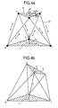
- FIG. 4 is a view explaining operation of a six-axis parallel link mechanism
- FIG. 5 is a view explaining bending parameters of a long member
- FIG. 6 is a view showing a strip member subjected to twist bending.
- the bending apparatus of the embodiment of the present invention is generally composed of a bending head 2, a material supply unit 3 for supplying a long member to the bending head 2, and control system (not shown) for controlling the bending head 2 and the material supply unit 3.
- the bending head 2 is composed of a base plate 7 that has a guide pipe 6 standing at the center thereof upright, the guide pipe 6 including a guide plate 5 that is composed of a guide hole 5a through which a long member 1 is passed and a support pipe 6a having the guide plate 5 attached to the front end thereof, a movable plate 9 disposed in front of the throttle device 6 and having a die 8 disposed at the center thereof for applying a bending force to the long member 1 supplied from the guide pipe 6, and six extendable units 12 disposed between the base plate 7 and the movable plate 9.
- Each of the extendable units 12 is composed of a hydraulic cylinder 10 and universal joints 11 disposed at both the end thereof.
- each hydraulic cylinder 10 is attached to the peripheral edge portion of the front surface of the base plate 7 and the universal joints 11 at the other end thereof is attached to the peripheral edge portion of the rear surface of the movable plate 9. It is preferable to set the outside size of the movable plate 9 smaller than the base plate 7 to prevent the long member 1 from interfering the movable plate 9 when it is bent.
- the bending head 2 is arranged as the six-axis parallel link mechanism that causes the movable plate 9 to execute a motion of a total of six degrees of freedom including three degrees of freedom of translational movement and three degrees of freedom of rotation with respect to the base plate 7 when the expandable units 12 expand and contract.
- the bending head 2 is arranged by disposing the guide pipe 6 and the die 8 to the six-axis parallel link mechanism.
- a six-axis parallel link motion base made by Tokyo Precision Instruments Co., Ltd. is used as the six-axis parallel link mechanism. Note that the six-axis parallel link motion base is a trade name of Tokyo Precision Instruments Co., Ltd.
- a potentiometer 26 for detecting a cylinder length and a servo valve 27 for controlling an operating fluid are mounted on each hydraulic cylinder 10.
- FIG. 3 is a plan view explaining the positional relationship among the base plate 7, the movable plate 9, and the six extendable units 12 in the six-axis parallel link motion base.
- FIG. 3 shows a state in which the six extendable units 12 are set to the same length. Accordingly, the base plate 7 is in parallel with the movable plate 9 with respect to the planes thereof, and the central axes of the respective plates are located on the same axis.
- the six extendable units 12 are installed approximately in a truss state bridging between each six pairs of the installing positions 16 and 19 that are located in the nearest distances between the base plate 7 and the movable plate 9 in the state that a triangle 22 connecting the three equally divided points of the base plate 7 is offset each other from a triangle 23 connecting the three equally divided points of the movable plate 9 by a rotational angle of 180°.
- the six-axis parallel link motion base can be explained in approximation to the model of a six-axis parallel link mechanism shown in FIG. 4A .
- the model has a truss structure arranged in the six-axis parallel link motion base shown in FIG. 3 such that the six extendable units 12 are joined between the base plate 7 and the movable plate 9 through pins by gathering the positions 16 and 16 of the respective two adjacent universal joints to one position.
- an xyz rectangular coordinates are set on the front surface of the base plate 7 using the central point O 1 of the guide hole 5a as an origin, and a z-axis is used as the central axis of the guide hole 5a.
- uvw rectangular coordinates are set using the central point O 2 of the die 8 mounted on the movable plate 9 as an origin, a w-axis is used as the central axis of the die 8, and a uv plane is made flush with the plane of the shape hole 8a of the die 8 (refer to FIG. 5 ).
- the central point of the movable plate 9, in other words, the central point O 2 of the die makes a translational movement in the three directions of the x-, y- and z-axes set on the base plate 7 and rotates about the respective u-, v- and w-axes set to the movable plate 9.
- FIG. 4B shows a state in which the movable plate 9 is moved with respect to the base plate 7, wherein the position of the origin O 2 of the movable plate 9 is represented by a position vector P as to the origin O 1 of the base plate 7, and the attitude of the movable plate 9 is represented by the matrix R of the rotational angle about the respective axes u, v, and w.
- the six-axis parallel link mechanism is manipulated, inverse kinematics for determining the lengths of the respective extendable units 12 from the position vector P and the matrix R of the rotational angle.
- the long member 1 is, for example, a round bar.
- offset a from the axial center of the guide pipe 6 to the central point of the die 8
- the distance from the front surface of the guide hole 5a to the central point of the die 8 b (inter-shape distance b) and the inclining angle ⁇ of the die 8 to a plane perpendicular to the axial center of the guide pipe 6 are set as the parameters.
- the die 8 has a shape hole 8a formed of the ridge lines of an inner wall that projects in the center direction of the pipe 8 and has triangular cross sections.
- the vertex of the triangular cross section that contacts with the long member is rounded as shown in Fig. 5 .
- the guide hole 5a and the shape hole 8a are formed in sizes obtained by adding clearances to the outside size of the cross section of the long member 1.
- ⁇ ⁇ (1 - cos ⁇ )
- b ⁇ sin ⁇
- the offset a is selected from the size, material (Al, Cu, steel, etc.), and the like of the round bar. In practical use, this parameter is determined according to a result of bending test performed using various materials.
- the parameters a, b, and ⁇ are related to the xyz coordinates (origin O 1 ) on the base plate 7 and the uvw coordinates (origin O 2 ) on the movable plate 9 each shown in FIG. 4A .
- the sheet of FIG. 4A includes both the y- and z-axes and both the v- and w-axes.
- the offset a can be represented by a value y on the xyz coordinates
- the inter-shape distance b can be represented by a value obtained by subtracting the height h of the guide pipe 6 from a value z on the xyz coordinates
- the inclining angle ⁇ can be represented by a rotational angle about the x-axis as to the origin O 2 on the movable plate 9.
- the height h of the guide pipe 6 is the height from the front surface of the base plate 7.
- P B shows a force necessary to bend the long member 1 in a curved shape
- P L shows a force for pushing the long member 1 in longitudinal direction thereof.
- the material supply unit 3 is composed of a frame member 25 fixed to the rear portion of the bending head 2 and a hydraulic cylinder 24 disposed to the frame member 25.
- the rear end of the long member 1 is pushed by the hydraulic cylinder 24 at a constant speed, thereby the long member 1 is fed through the guide hole 5a of the bending head 2.
- a dent or a clamp is formed at the tip end of the hydraulic cylinder 24 to fix the terminal end
- the control system is composed of a personal computer.
- the personal computer calculates the lengths of the respective extendable units 12 from the input values of the bending parameters (a, b, ⁇ , and ⁇ ), actuates the hydraulic cylinders 10 through the servo valve 27, controls the position and attitude of the movable plate 9 of the bending head 2, and also controls the feed speed of the long member 1 fed by the hydraulic cylinder 24 of the material supply unit.
- the bending parameters (a, b, ⁇ , and ⁇ ) are previously determined by an experiment and stored because they are different according to the shape, size, material, and the like of the long member 1.
- the long member bent by the bending apparatus of the present invention includes a strip member, in addition to a pipe member, a bar member, and a shape member having round, oval, and square cross section.
- the strip member can be bent in a spiral shape by bending it in a sheet thickness direction with a certain radius as well as by applying twist thereto.
- twist distortion caused by bending can be corrected by applying twist to the strip member.
- An automobile window frame for example, is exemplified as a bent product made of an asymmetrical strip member.
- the long member bending apparatus comprises the base plate including the bending head and the guide pipe, the movable plate having the die, and the six extendable units connecting both the plates, the apparatus can be arranged as an apparatus having a simple structure and high rigidity, can bend a pipe member, a bar member, and the like with sufficient accuracy. Further, since the movable plate is arranged so as to rotate about the axial center of the die, the bending apparatus has an effect that it can be applied to a strip member that must be twisted when it is bent.
Landscapes
- Engineering & Computer Science (AREA)
- Mechanical Engineering (AREA)
- Bending Of Plates, Rods, And Pipes (AREA)
Claims (2)
- Vorrichtung zum Biegen länglicher Produkte mit:einem Biegekopf (2), um ein längliches Produkt (1) in eine gekrümmte Form zu biegen,einer Materialzuführeinheit (3), um das längliche Produkt (1) dem Biegekopf zuzuführen, undeinem Steuersystem, um den Biegekopf (2) und die Materialzuführeinheit zu steuern,dadurch gekennzeichnet, dass die sechs ausziehbaren Einheiten (12) die allgemeinen Anschlussstücke (11) mit den Kantenbereichen an der Außenfläche der Grundplatte (7) und der beweglichen Platte (9) verbinden, um in einem Verstrebungszustand zu gelangen, und einen parallelen Verbindungsmechanismus zu errichten, um zu bewirken, dass die bewegliche Platte (9) eine Bewegung durchführt, die drei Freiheitsgrade hinsichtlich einer translatorischen Bewegung und drei Freiheitsgrade hinsichtlich einer Drehbewegung in Bezug auf xyz-Koordinaten aufweist, die auf der Grundplatte (7) durch Expandieren und Kontrahieren der hydraulischen Zylinder eingestellt werden.
wobei der Biegekopf (2) aufweist:eine Grundplatte (7) mit einem Führungsrohr (6), durch die eine Führungsöffnung (5a) zum Durchführen des länglichen Produktes (1), das von der Zuführeinheit (1) zugeführt wird, da drinnen gebildet ist, wobei sie aufrecht in deren Mitte steht,eine bewegliche Platte (9) mit einer Pressform (8), die eine Biegekraft auf das längliche Produkt (1), das von dem Führungsrohr (6) zugeführt wurde, nach vorne aufbringt, während es dadurch gelangt, wobei sie an deren Mitte angeordnet ist, undsechs ausziehbaren Einheiten (12), die hydraulische Zylinder (10) umfassen, die zwischen der Grundplatte (7) und der beweglichen Platte (9) und allgemeinen Anschlussstücken (11) angeordnet sind, die jeweils an beiden Enden der hydraulischen Zylinder (10) angebracht sind, - Vorrichtung zum Biegen länglicher Produkte nach Anspruch 1, dadurch gekennzeichnet, dass das Steuersystem die Länge der entsprechenden hydraulischen Zylinder (10) einstellt, indem der Ort und die Neigung der beweglichen Platte (9) hinsichtlich der Grundplatte (7) und der Drehwinkel der beweglichen Platte (9) um deren zentralen Achse davon eingestellt werden.
Applications Claiming Priority (2)
| Application Number | Priority Date | Filing Date | Title |
|---|---|---|---|
| JP2001187310 | 2001-05-18 | ||
| JP2001187310A JP4081593B2 (ja) | 2001-05-18 | 2001-05-18 | 長尺材の曲げ加工装置 |
Publications (3)
| Publication Number | Publication Date |
|---|---|
| EP1260287A2 EP1260287A2 (de) | 2002-11-27 |
| EP1260287A3 EP1260287A3 (de) | 2003-05-07 |
| EP1260287B1 true EP1260287B1 (de) | 2008-07-16 |
Family
ID=19026612
Family Applications (1)
| Application Number | Title | Priority Date | Filing Date |
|---|---|---|---|
| EP02253321A Expired - Lifetime EP1260287B1 (de) | 2001-05-18 | 2002-05-13 | Vorrichtung zum Biegen länglicher Produkte |
Country Status (6)
| Country | Link |
|---|---|
| US (1) | US6662613B2 (de) |
| EP (1) | EP1260287B1 (de) |
| JP (1) | JP4081593B2 (de) |
| KR (1) | KR100574550B1 (de) |
| CN (1) | CN1231310C (de) |
| DE (1) | DE60227601D1 (de) |
Families Citing this family (18)
| Publication number | Priority date | Publication date | Assignee | Title |
|---|---|---|---|---|
| JP4777553B2 (ja) * | 2001-08-08 | 2011-09-21 | 株式会社オプトン | 曲げ加工装置 |
| US8863565B2 (en) * | 2005-03-03 | 2014-10-21 | Nippon Steel & Sumitomo Metal Corporation | Three-dimensionally bending machine, bending-equipment line, and bent product |
| US8919171B2 (en) * | 2005-03-03 | 2014-12-30 | Nippon Steel & Sumitomo Metal Corporation | Method for three-dimensionally bending workpiece and bent product |
| JP4713202B2 (ja) * | 2005-04-06 | 2011-06-29 | タマティーエルオー株式会社 | 多軸微細加工方法及び装置 |
| US20090199610A1 (en) * | 2005-04-06 | 2009-08-13 | Kikuchi Seisakusho Co., Ltd. | Actuator, parallel link mechanism using the same, and long material bending device |
| JP4897254B2 (ja) * | 2005-07-15 | 2012-03-14 | 株式会社菊池製作所 | アクチュエータ並びにこれを用いたパラレルリンク機構及び長尺材の曲げ加工装置 |
| CN100443210C (zh) * | 2006-10-20 | 2008-12-17 | 张家港市合丰机械制造有限公司 | 倾角式回转座 |
| US8307685B2 (en) * | 2008-04-09 | 2012-11-13 | Shape Corp. | Multi-directionally swept beam, roll former, and method |
| US8333096B2 (en) | 2009-09-21 | 2012-12-18 | Shape Corp. | Method of forming three-dimensional multi-plane beam |
| FR2988309B1 (fr) * | 2012-03-24 | 2015-06-05 | Numalliance | Machine de cintrage a tete de pliage mobile autour d'un nez de pliage fixe |
| JP6063241B2 (ja) * | 2012-12-14 | 2017-01-18 | 株式会社菊池製作所 | 曲げ加工装置 |
| AT513973B1 (de) * | 2013-02-22 | 2014-09-15 | System7 Railsupport Gmbh | Stopfaggregat für eine Gleisstopfmaschine |
| CN105891008A (zh) * | 2015-01-07 | 2016-08-24 | 海隆防腐技术工程(太仓)有限公司 | 弯曲测试仪 |
| CN106903716B (zh) * | 2017-01-22 | 2019-10-29 | 浙江厚达智能科技股份有限公司 | 曲线伸缩式机械手 |
| CN110180930A (zh) * | 2019-06-13 | 2019-08-30 | 山东大学 | 渐进式空间自由弯管成形机构 |
| CN114570807B (zh) * | 2022-01-25 | 2023-04-07 | 南京航空航天大学 | 一种基于芯棒旋转的六轴弯曲装置及方法 |
| CN117325135A (zh) * | 2023-10-17 | 2024-01-02 | 北京星光凯明智能装备有限公司 | 可变下铰支座位置的六自由度并联机器人及其求解方法 |
| CN117960863A (zh) * | 2024-02-06 | 2024-05-03 | 浙江大学 | 一种可加工不同外径管件的a值可变自由弯曲成形装置 |
Family Cites Families (9)
| Publication number | Priority date | Publication date | Assignee | Title |
|---|---|---|---|---|
| US4062216A (en) * | 1974-07-23 | 1977-12-13 | Daiichi Koshuha Kogyo Kabushiki Kaisha | Metal bending methods and apparatus |
| JPS6033569B2 (ja) * | 1983-01-21 | 1985-08-03 | 日立金属株式会社 | 湾曲調整スタンド |
| JPS63104726A (ja) * | 1986-10-22 | 1988-05-10 | Hitachi Ltd | 曲げ加工装置 |
| KR960703357A (ko) * | 1993-07-08 | 1996-08-17 | 나카타 츠토무 | 롤 성형기 스탠드의 지지 방법과 그 장치 및 지지 플랫폼 위치의 계측 방법과 그 장치(method and apparatus for supporting a roll molding machine stand, and method and apparatus for measuring a supporting platform position) |
| JP3733176B2 (ja) * | 1996-07-10 | 2006-01-11 | 株式会社オプトン | 曲げ加工装置 |
| JPH1024327A (ja) * | 1996-07-10 | 1998-01-27 | Opton Co Ltd | 曲げ加工装置 |
| DE19717232A1 (de) * | 1997-04-24 | 1998-10-29 | Suban Ag | Verfahren und Vorrichtung zum dreidimensionalen Biegen von Metall-Hohlprofilen |
| DE19830962B4 (de) * | 1998-07-10 | 2005-07-21 | Fraunhofer-Gesellschaft zur Förderung der angewandten Forschung e.V. | Vorrichtung und Verfahren zum Biegen stangenartiger Werkstücke |
| DE19956796A1 (de) * | 1999-11-25 | 2001-06-13 | Palima W Ludwig & Co | Biegevorrichtung für das 2- und 3-dimensionale Profilbiegen |
-
2001
- 2001-05-18 JP JP2001187310A patent/JP4081593B2/ja not_active Expired - Lifetime
-
2002
- 2002-05-13 EP EP02253321A patent/EP1260287B1/de not_active Expired - Lifetime
- 2002-05-13 DE DE60227601T patent/DE60227601D1/de not_active Expired - Lifetime
- 2002-05-17 US US10/150,452 patent/US6662613B2/en not_active Expired - Lifetime
- 2002-05-17 CN CNB021198888A patent/CN1231310C/zh not_active Expired - Lifetime
- 2002-05-17 KR KR1020020027421A patent/KR100574550B1/ko not_active Expired - Fee Related
Also Published As
| Publication number | Publication date |
|---|---|
| JP2002346640A (ja) | 2002-12-03 |
| US6662613B2 (en) | 2003-12-16 |
| KR100574550B1 (ko) | 2006-04-27 |
| US20020170329A1 (en) | 2002-11-21 |
| CN1386595A (zh) | 2002-12-25 |
| CN1231310C (zh) | 2005-12-14 |
| EP1260287A2 (de) | 2002-11-27 |
| JP4081593B2 (ja) | 2008-04-30 |
| KR20020089159A (ko) | 2002-11-29 |
| EP1260287A3 (de) | 2003-05-07 |
| HK1050340A1 (en) | 2003-06-20 |
| DE60227601D1 (de) | 2008-08-28 |
Similar Documents
| Publication | Publication Date | Title |
|---|---|---|
| US6662613B2 (en) | Long member bending apparatus | |
| US6983633B2 (en) | Apparatus for roll hemming with zero angle deflection | |
| EP0934783A2 (de) | Biegevorrichtung sowie Verfahren zum Biegen | |
| JP4831867B2 (ja) | 産業用ロボットおよびその動作方法 | |
| JPH07290158A (ja) | ローラーヘミング装置 | |
| JP5090636B2 (ja) | 曲げ加工装置 | |
| JP4972548B2 (ja) | アクチュエータ並びにこれを用いたパラレルリンク機構及び長尺材の曲げ加工装置 | |
| JP3243540B2 (ja) | ロール曲げ方法 | |
| JPH03106529A (ja) | ケーブル用ベンダー | |
| JP2651710B2 (ja) | 細径金属管の曲げ加工装置 | |
| JPH0741320B2 (ja) | 細径金属管の曲げ加工装置 | |
| JP4897254B2 (ja) | アクチュエータ並びにこれを用いたパラレルリンク機構及び長尺材の曲げ加工装置 | |
| JP2003127631A (ja) | 中空スタビライザ | |
| JP3507369B2 (ja) | テーパー管の曲げ加工装置 | |
| JPH07222321A (ja) | ケーブル曲げ装置 | |
| KR100489932B1 (ko) | 봉강재의 벤딩장치 | |
| JP2741229B2 (ja) | 細径金属管の曲げ加工装置 | |
| JP2651711B2 (ja) | 細径金属管の曲げ加工装置 | |
| HK1050340B (en) | Long member bending apparatus | |
| JP3354963B2 (ja) | 配管曲がり矯直機 | |
| JPH0513012B2 (de) | ||
| JP2651716B2 (ja) | 細径金属管の曲げ加工装置 | |
| JP7816221B2 (ja) | パイプベンダー | |
| JPS6333925B2 (de) | ||
| JPH10314849A (ja) | 長尺ワークの曲げ・捩り加工装置 |
Legal Events
| Date | Code | Title | Description |
|---|---|---|---|
| PUAI | Public reference made under article 153(3) epc to a published international application that has entered the european phase |
Free format text: ORIGINAL CODE: 0009012 |
|
| AK | Designated contracting states |
Kind code of ref document: A2 Designated state(s): AT BE CH CY DE DK ES FI FR GB GR IE IT LI LU MC NL PT SE TR |
|
| AX | Request for extension of the european patent |
Free format text: AL;LT;LV;MK;RO;SI |
|
| PUAL | Search report despatched |
Free format text: ORIGINAL CODE: 0009013 |
|
| AK | Designated contracting states |
Designated state(s): AT BE CH CY DE DK ES FI FR GB GR IE IT LI LU MC NL PT SE TR |
|
| AX | Request for extension of the european patent |
Extension state: AL LT LV MK RO SI |
|
| RIC1 | Information provided on ipc code assigned before grant |
Ipc: 7B 21D 7/02 B Ipc: 7B 21D 7/025 A |
|
| 17P | Request for examination filed |
Effective date: 20031107 |
|
| AKX | Designation fees paid |
Designated state(s): DE FI FR GB IT SE |
|
| 17Q | First examination report despatched |
Effective date: 20061017 |
|
| GRAP | Despatch of communication of intention to grant a patent |
Free format text: ORIGINAL CODE: EPIDOSNIGR1 |
|
| RAP1 | Party data changed (applicant data changed or rights of an application transferred) |
Owner name: KIKUCHI SEISAKUSHO CO., LTD. |
|
| RIN1 | Information on inventor provided before grant (corrected) |
Inventor name: FUJITA, KATSUHIRO Inventor name: TERAUCHI, YUJI Inventor name: ICHIRYU, KEN |
|
| RIN1 | Information on inventor provided before grant (corrected) |
Inventor name: ICHIRYU, KEN Inventor name: TERAUCHI, YUJI Inventor name: FUJITA, KATSUHIRO |
|
| GRAS | Grant fee paid |
Free format text: ORIGINAL CODE: EPIDOSNIGR3 |
|
| GRAA | (expected) grant |
Free format text: ORIGINAL CODE: 0009210 |
|
| AK | Designated contracting states |
Kind code of ref document: B1 Designated state(s): DE FI FR GB IT SE |
|
| REG | Reference to a national code |
Ref country code: GB Ref legal event code: FG4D |
|
| RIN1 | Information on inventor provided before grant (corrected) |
Inventor name: FUJITA, KATSUHIRO Inventor name: ICHIRYU, KEN Inventor name: TERAUCHI, YUJI |
|
| REF | Corresponds to: |
Ref document number: 60227601 Country of ref document: DE Date of ref document: 20080828 Kind code of ref document: P |
|
| PG25 | Lapsed in a contracting state [announced via postgrant information from national office to epo] |
Ref country code: FI Free format text: LAPSE BECAUSE OF FAILURE TO SUBMIT A TRANSLATION OF THE DESCRIPTION OR TO PAY THE FEE WITHIN THE PRESCRIBED TIME-LIMIT Effective date: 20080716 |
|
| PLBE | No opposition filed within time limit |
Free format text: ORIGINAL CODE: 0009261 |
|
| STAA | Information on the status of an ep patent application or granted ep patent |
Free format text: STATUS: NO OPPOSITION FILED WITHIN TIME LIMIT |
|
| 26N | No opposition filed |
Effective date: 20090417 |
|
| PG25 | Lapsed in a contracting state [announced via postgrant information from national office to epo] |
Ref country code: IT Free format text: LAPSE BECAUSE OF FAILURE TO SUBMIT A TRANSLATION OF THE DESCRIPTION OR TO PAY THE FEE WITHIN THE PRESCRIBED TIME-LIMIT Effective date: 20080716 |
|
| PG25 | Lapsed in a contracting state [announced via postgrant information from national office to epo] |
Ref country code: SE Free format text: LAPSE BECAUSE OF FAILURE TO SUBMIT A TRANSLATION OF THE DESCRIPTION OR TO PAY THE FEE WITHIN THE PRESCRIBED TIME-LIMIT Effective date: 20081016 |
|
| REG | Reference to a national code |
Ref country code: FR Ref legal event code: ST Effective date: 20100129 |
|
| PG25 | Lapsed in a contracting state [announced via postgrant information from national office to epo] |
Ref country code: FR Free format text: LAPSE BECAUSE OF NON-PAYMENT OF DUE FEES Effective date: 20090602 |
|
| PGFP | Annual fee paid to national office [announced via postgrant information from national office to epo] |
Ref country code: GB Payment date: 20120301 Year of fee payment: 11 |
|
| PGFP | Annual fee paid to national office [announced via postgrant information from national office to epo] |
Ref country code: DE Payment date: 20120309 Year of fee payment: 11 |
|
| GBPC | Gb: european patent ceased through non-payment of renewal fee |
Effective date: 20130513 |
|
| PG25 | Lapsed in a contracting state [announced via postgrant information from national office to epo] |
Ref country code: DE Free format text: LAPSE BECAUSE OF NON-PAYMENT OF DUE FEES Effective date: 20131203 |
|
| REG | Reference to a national code |
Ref country code: DE Ref legal event code: R119 Ref document number: 60227601 Country of ref document: DE Effective date: 20131203 |
|
| PG25 | Lapsed in a contracting state [announced via postgrant information from national office to epo] |
Ref country code: GB Free format text: LAPSE BECAUSE OF NON-PAYMENT OF DUE FEES Effective date: 20130513 |