EP1260376A2 - Thermotransferfarbdruckverfahren und -vorrichtung - Google Patents
Thermotransferfarbdruckverfahren und -vorrichtung Download PDFInfo
- Publication number
- EP1260376A2 EP1260376A2 EP02356097A EP02356097A EP1260376A2 EP 1260376 A2 EP1260376 A2 EP 1260376A2 EP 02356097 A EP02356097 A EP 02356097A EP 02356097 A EP02356097 A EP 02356097A EP 1260376 A2 EP1260376 A2 EP 1260376A2
- Authority
- EP
- European Patent Office
- Prior art keywords
- ribbons
- printing
- support
- block
- ribbon
- Prior art date
- Legal status (The legal status is an assumption and is not a legal conclusion. Google has not performed a legal analysis and makes no representation as to the accuracy of the status listed.)
- Withdrawn
Links
Images


Classifications
-
- B—PERFORMING OPERATIONS; TRANSPORTING
- B41—PRINTING; LINING MACHINES; TYPEWRITERS; STAMPS
- B41J—TYPEWRITERS; SELECTIVE PRINTING MECHANISMS, i.e. MECHANISMS PRINTING OTHERWISE THAN FROM A FORME; CORRECTION OF TYPOGRAPHICAL ERRORS
- B41J35/00—Other apparatus or arrangements associated with, or incorporated in, ink-ribbon mechanisms
- B41J35/22—Mechanisms permitting the selective use of a plurality of ink ribbons
Definitions
- the present invention relates to the color printing technique of a printable support using a known thermal transfer process, consisting of to ensure, by localized heat supply, the transfer of dyes carried by a suitable substrate, towards a receiving support on which these dyes are fixed.
- the invention relates, more particularly, to the technical field in which this basic principle is implemented by means of technical provisions ensuring the transfer of points which, by color combination according to the principle of synthesis additive or subtractive synthesis, give rise to the formation of images composed, of multiple and varied colors.
- the technical field concerned is, more particularly, that of printing. supports in the form of boards, strips, sheets, in any suitable material compatible with receiving and fixing colored pigments and whose destination finish can be varied.
- Such a technique is widely used for the creation of billboards or advertising panels.
- the implementation of such a technique consists in unwinding, from a storage roll, a strip of suitable material constituting a support which is engaged in a device to bring back, on this support, a colored impression which is, generally, controlled, in its form, in the choice of colors, by through a computer center requiring the device to run a number of passes to form the pattern and obtain the combination of desired colors.
- thermal transfer of the dyes is carried out by passing successive, from a supply of dyes carried by a ribbon or the like, stored in a cake which should be changed for each pass and for each color.
- Another proposal of the prior art has been to provide a device color printing by thermal transfer of a single wafer or spool bearing a ribbon which is composed of successive series of segments of primary colors, such as three or four, which are thus renewed from series to series.
- the operating technique of such a device then consists in placing, under the print head, the segment of a series of ribbon corresponding to the color desired, then unroll the ribbon for the next pass, so as to route, under the head, the segment of the different or complementary color that is appropriate printing.
- the object of the invention is to meet the need to be able to have a printing technique on printable support by thermal transfer of dyes, which is able to involve an attractive acquisition cost for what relates to the technical means to be implemented and which allows obtaining of various colored patterns at a unit price per unit area which is also interesting.
- Another object of the invention is to offer a technique which allows a execution of patterns of large areas, of relative complexity, of good definition and various colors, at a production rate significantly faster than that of the devices currently available.
- the invention also relates to a spool for a ribbon for printing by heat transfer, of the type comprising a ribbon winding mandrel.
- this coil is characterized in that it comprises, in in addition, a hub for limiting the rotational torque of the mandrel.
- the torque limiting hub can be made in any suitable way and, by example, using viscous coupling means.
- the limiting hub of couple comprises a sleeve which is integral with the mandrel and produced in a compressible material and which defines the receiving bore of a drive axis of the coil.
- the sleeve is then made of cellular synthetic material, such as, for example but not exclusively, a crosslinked polyethylene foam which preferably, but not strictly necessary, has a density between 40 and 50 kg / m 3 .
- the torque limiting hub is, from preferably adapted to limit the drive torque to a value between 0.5 N / cm and 2 N / cm, so as to apply tension to the printing ribbon sufficient without risking damage to the latter.
- the coil comprises flanges.
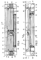
- Fig. 1 is a schematic perspective of the device according to the invention.
- Fig. 2 is a partial perspective, similar to FIG. 1, but illustrating a characteristic arrangement of the device.
- Fig. 3 is a sectional elevation taken substantially along the plane III-III of FIG. 1.
- Fig. 4 is a plan view in section taken along line IV-IV of FIG. 3.
- Fig. 5 is a cross section taken, on a larger scale, along the line VV of FIG. 3.
- Fig. 6 is a partial plan view taken along line VI-VI of FIG. 5.
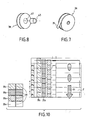
- Figs. 7 and 8 are partial perspectives showing, on a different scale, two constituent elements of the device.
- Fig. 9 is a partial schematic perspective view of a winding assembly for the printing ribbon of the device illustrated in FIG. 1.
- Fig. 10 is a schematic view illustrating, more particularly, an initial characteristic phase of implementing the method according to the invention.
- Figs. 11, 12 and 13 are schematic views illustrating three specific steps for implementing the method.
- Figs. 1 and 2 show , schematically, a device 1 for implementing the process for printing a support 2 by thermal transfer of dyes or pigments.
- the support 2 is constituted by a strip coming from a storage roller 3 and unwound in the direction of the arrow f 1 , denoted by convention in what follows "longitudinal direction".
- the device is placed, for its operation, under the dependence of a unit 4 for storing computer data and for controlling the various motor and active constituent parts of the device, in relation to a program for establishing a colored pattern, such as than that shown in dashed lines under the reference 5 in FIG. 1.
- the device comprises structurally, from FIGS. 1 to 4 , a frame 5 consisting of spacer members linked by parallel cheeks 6 , associated with cowls 7 with which they delimit two compartments 8 and 9 whose functions appear in the following.
- the frame 5 delimits a window or through passage 10 (fig. 5), reserved for the movement of the strip 2 and including, for this purpose, for example in relation to the face 1b, a duo of superposed rollers 11 and 12 whose ends are provided with drive means, of the type with perforations and pins for example.
- One of the rollers, such as the roller 12 is provided with a connection with a drive motor in translation in the longitudinal direction f 1 , such a motor, designated by the reference 14, being of any type suitable for ensuring, by successive increments, an intermittent longitudinal scrolling at a pitch p which is more particularly discussed in the following in connection with the printing process.
- the frame 5 comprises, consequently, although this is not shown, intermediate flanges delimiting support bearings for the ends of the rollers 11 and 12, as well as means allowing the temporary fixing of the motor 14 which may, if appropriate, be associated to a multiplier or multiplier system.
- the duo of rollers 11, 12 is situated, with respect to the direction of travel in the direction of the arrow f 1 , downstream of a printing table or platen 15 which also extends between the cheeks 6 on which this plate or table is fixed.
- the plate or printing table 15 can constitute a member constituting the frame 5.
- the device comprises a guide track 20 comprising, as can be seen more particularly of fig. 5, for example and preferably but not limited to, a slide 21 located near the introduction face 1a and a guide rail 22 placed in line with the face 1b.
- the constituent elements of the guideway can be an integral part of the frame 5 by being linked to the cheeks 6.
- the guideway 20 is reserved for the support of a printing block B which can be animated by alternating rectilinear displacements in a direction defined by track 20 and which is considered, by convention, as transverse and orthogonal with respect to the longitudinal direction f 1 .
- This transverse direction is materialized by a double arrow bearing the references f 2 and f 3 corresponding, by definition, to two directions of movement for the block, called "outward-printing stroke" and "return stroke", respectively
- the block B comprises a carriage 23 which cooperates with the slide 21 and the rail 22.
- the carriage 23 is linked to a command in translation in the direction of the arrows f 2 and f 3 , such a command, shown in FIG. 6, being, for example, constituted in the form of a strap or notched belt 26 established in a loop to surround two wheels or pulleys 27 which one is driven by coupling with a motor 28.
- a command shown in FIG. 6, being, for example, constituted in the form of a strap or notched belt 26 established in a loop to surround two wheels or pulleys 27 which one is driven by coupling with a motor 28.
- the assembly, driving pulley 27 and motor 28 is advantageously arranged in compartment 9 , the cover 7 of which provides accessibility for maintenance, adjustment and replacement operations, as illustrated. more precisely by fig. 1.
- the printing block B is held, by the guide track 20, in a horizontal plane, superimposed on the plate or printing table 15, reserving, as illustrated in FIG. 5, an interval or spacing E constant with respect to the latter and which is situated in the extension of the aperture 10.
- the carriage 23 of the printing block has two slides 30 established like vertical balusters and which are capable of ensuring the guiding a print head 31 which can be controlled in reciprocating movement along a vertical trajectory by a servo motor 32.
- the thermal head possibly returned to the high position by means of elastic members, can thus occupy a low position, so-called printing, in which it projects inside the interval E and a high position, called retraction, in which it is erased with respect to this interval E.
- the power conditions of the servo motor 32 are determined and controlled by the operation of the unit 4, as are the functional characteristics of the thermal head which is preferably of the needle type.
- the device implements heat transfer means which consist of ribbons of flexible material arranged to extend in the interval E by being placed in parallel and, preferably but not exclusively, in a non-contiguous manner with respect to each other, in exactly the direction f 2 , f 3 .
- the different ribbons thus occupy a plane which passes between the carriage 23 and the plate or table 15.
- ribbons made of flexible material, the face of which, facing the table or plate 15, has a coating based on thermally transferable dyes or pigments.
- Different possibilities can be retained within the meaning of the invention to constitute the heat transfer means and, in a first variant, it can be provided to constitute them on the basis of at least two ribbons or, again, three, reserving the characteristic that each ribbon is provided with a layer of uniform dye over its entire length, it being understood that this uniform color is different from one ribbon to another.
- the ribbons are four in number and are, respectively, coated with black, magenta, cyan and yellow dyes or pigments, for example arranged in this order starting from face 1b in the direction of face 1a.
- the ribbons 35 are delivered from reels or flanged wafers 36, called debitettes (fig. 7) which can be easily adapted in a support 37 disposed in the compartment 9.
- the ribbons 35 are, moreover, supported by wafers or coils 38 with flanges, called receivers, which are mounted on a continuous winding assembly 39 through a torque limiting mechanism.
- the assembly 39 is fixed to a housing, such as 40, disposed in the compartment 8, to which access is reserved by means of the removable cover 7 as illustrated in FIG. 2.
- the means for continuously rotating the receiving coils 38 are intended to maintain, in an implementation phase of the method, the tapes 35 stretched by a tensile stress.
- the assembly 39 comprises, as illustrated by FIGS.
- a motor 41 the single output shaft 41 a of which is common to the various take-up reels 38.
- Each take-up reel 28 comprises a mandrel 42 for winding the corresponding ribbon.
- the assembly 39 also involves for each coil 38 a friction-limiting torque coupling 43 cooperating with the mandrel and connecting the coil to the output shaft 41 a .
- the coupling forms a torque limiting hub 43 and is, preferably, constituted by a ring or a tubular sleeve forming the hub and then defining the receiving bore of the drive shaft 41 a .
- the material of the hub 43 is chosen for its coefficient of friction and for its ability to withstand a radial compression stress while being elastically deformable.
- the hub or sleeve 43 is produced in a crosslinked polyethylene foam chosen to have, preferably but not necessarily, a density of between 40 kg / m 3 and 50 kg / m 3 .
- the hub 43 is then preferably secured by bonding with the mandrel 42.
- the device according to the invention also comprises complementary means for ensuring the tensioning of the ribbons 35 .
- complementary means include, in line with the supply coils 36, a series of clamps 50 , each of which is specific to a ribbon, so as to be able to pinch and immobilize them.
- the clamps 50 are located in the compartment 9 and are formed by electromagnets with a closed rest position in which, apart from any supply, these electromagnets pinch and immobilize the ribbons 35 at the output of the coils 37, in such a way that these ribbons are then constrained in tension through the assembly 39.
- the device also comprises means carried by the block B to ensure the temporary connection of the latter during part of its movements with the ribbons 35.
- Such means illustrated in FIGS. 3, 4, 5 and 6, include clamps 51 which are carried by the carriage 23, so as to be able to act by pinching on each of the ribbons to immobilize the latter in relative displacement relative to the block B.
- the clamps 51 are constituted by electromagnets which have the characteristic of being in the open rest position, that is to say that in the absence of electrical supply they release the strips 35.
- the electromagnets 51 are controlled in supply via the unit 4.
- the process for printing in color of the support 2 by thermal transfer according to the invention involves the following operating steps.
- the various ribbons 35 After the various ribbons 35 have been put in place , they are put under relative tension by closing the electromagnets 50 which constitute blocking points capable of withstanding the tensile stress which results from the supply of the motor 41 and of the 'driving in rotation of the receiving coils 38 via the torque limiting hubs 43.
- the hubs 43 are then adapted to limit, preferably but not exclusively, the driving torque to a value between 0.5 N / cm and 2 N / cm.
- the drive shaft 41 has , preferably but not strictly necessary, at least one longitudinal rib 41 b projecting from its surface, as shown fig. 9.
- the bore of the hub 43 of each coil 38 then has a diameter less than the thickness or diameter of the axis 41 a at the level of the rib 41 b .
- the rib 41 b allows to impart to the axis 41 has a shape that is not a circular cylinder and which does not have rotational symmetry.
- the cylinder 41 a could, in the same direction, have, for example, an elliptical or oval cross section.
- the different ribbons are stretched to occupy a common plane above the plate 15, without it resulting from untimely unwinding from the supply coils 36.
- the motor 41 is therefore kept under tension at the same time as the electromagnets 51 are devoid of power, so as to free the free passage of the ribbons 35 relative to the carriage 23.
- the transverse translation drive member 28 is supplied with power to place the printing unit B in the starting standby position, that is to say substantially in line with the flange 6 corresponding to the compartment 8. In such a state, the control servo motor 32 maintains the thermal print head in the retracted position.
- the strip 2 unwound from the roller 3 is engaged in the window 10 to be brought to cross the interval E by passing between the table 15 and the carriage 23. In this state, the strip 2 is taken over by the duo of 11-12 cylinders responsible for ensuring the incremental drive of said strip in the longitudinal direction f 1 .
- a preparatory step consists in carrying out the real start-up of the device to take account of a particular structural characteristic due to the fact that the different ribbons 35 are established parallel to one another in the same plane, without be longitudinally contiguous.
- a first printing pass is made on the support 2 from an initial state and concerns for example only the first ribbon such as the ribbon 1 carrying for example the black dye.
- the first printing pass is carried out by controlling by the motor 28 the displacement of the block B in the direction of the arrow f 2 after having supplied the motor 32 to lower the heat transfer head 31 to the printing position. in which it applies the different ribbons to the support 2 in the interval E.
- the thermal head is supplied in such a way that only its part corresponding to the ribbon 35 1 is activated so as to transfer to the support 2 during the pass P1 the dye of the ribbon 35 1 over the entire width of the latter and possibly onto its useful length between the cheeks 6.
- FIG. 10 only appears, by way of explanation, only a printing part established locally over the width of the support 2, but it should be understood that printing over the entire width is possible.
- a second step takes place in substantially the same way, after longitudinal displacement in the direction of the arrow f 1 of the support 2 which is driven in scrolling in the corresponding direction with a pitch p whose width is at most equal to the width of the ribbons 35.
- the pass P2 makes it possible theoretically to carry out a second printing pass for the ribbon 35 1 , which is contiguous with the first. Taking into account the fact that the ribbons 35 are not contiguous, each longitudinal displacement of the support by a value equal to the width of a ribbon reduces the useful transverse range of the other ribbons, but the examination of FIG.
- an active printing function after commissioning as above, for obtaining a pattern such as 5, involves the thermal transfer of the dyes of one, more or all of the ribbons over all or part of their useful length depending on the pattern to be produced and the combination of colors that should be given to it, conditions which are controlled by unit 4.
- the print head transfers by its activated parts the dyes of the ribbons 35 1 and 35 2 which are applied by the head to the support 2, so that the thermal transfer takes place according to a known process. During this pass, the transfer head slides over the ribbons 35 1 to 35 4 which are stationary.
- the carriage 23 exerts a tensile force on the only two ribbons 35 1 and 35 2 which have just been used, so as to unwind them from the supply coils 36 to rewind them on the receiving coils 38 and replace thus above the support 2 portions of ribbons 35 1 and 35 2 which have not undergone any alteration of their layer of pigments or dyes, and therefore capable, during the next pass, of transferring any supports to the support 2 dyes they contain.
- each print pass involves use only parts of ribbon necessary for obtaining the colored image to be reproduced, so the expense or cost of getting the pattern is only limited to the use of the necessary dyes, without involving a loss of useful length active unused ribbons, as occurs with devices in the prior art.
- the unwinding after a go-print run during of the return race only takes place for the part actually used of each ribbon, and only concerns those ribbons that were used during the pass question.
- each pass or one-way print run makes it possible to involve the transfer for all or part of the four ribbons, in situations of contiguous prints, so that for a return trip of the printing block B the possible combination of the deposition by thermal transfer of four dyes can occur in a single operation.
- Another characteristic of the process is to limit each time the partial use of the tape or ribbons concerned and to ensure the unwinding and rewinding thereof only according to the length used, since the unwinding takes place during the return stroke of the printing unit 31 by means of the relevant clamp (s) 51 , the supply of which can be interrupted during the return stroke if it is necessary to limit the unwinding and rewinding only part of the useful length of the strip or strips extending between the cheeks 6 .
- a characteristic of the device of the invention also resides in the structure of the frame and in the presence of the two extreme lateral compartments 8 and 9 in which the supply coils, the receiving coils, as well as the servo motors 28 and 39 are housed . It thus becomes practical to change the supply coils when the latter are empty, and to extract the receiving coils when they are full, to replace them with new sets of coils or wafers 9.
- the carriage 23 could carry, via the slides 30 as many heat transfer heads as there are ribbons, so that each is assigned to one of the latter, and is therefore controlled in displacement towards the retracting position or towards the printing position in a clean and selective manner from the command instructions of the unit 4.
Landscapes
- Impression-Transfer Materials And Handling Thereof (AREA)
- Electronic Switches (AREA)
- Thermal Transfer Or Thermal Recording In General (AREA)
Applications Claiming Priority (2)
| Application Number | Priority Date | Filing Date | Title |
|---|---|---|---|
| FR0106821 | 2001-05-23 | ||
| FR0106821A FR2825046B1 (fr) | 2001-05-23 | 2001-05-23 | Procede et dispositif d'impression en couleurs d'un support par transfert thermique |
Publications (2)
| Publication Number | Publication Date |
|---|---|
| EP1260376A2 true EP1260376A2 (de) | 2002-11-27 |
| EP1260376A3 EP1260376A3 (de) | 2003-11-12 |
Family
ID=8863602
Family Applications (1)
| Application Number | Title | Priority Date | Filing Date |
|---|---|---|---|
| EP02356097A Withdrawn EP1260376A3 (de) | 2001-05-23 | 2002-05-23 | Thermotransferfarbdruckverfahren und -vorrichtung |
Country Status (2)
| Country | Link |
|---|---|
| EP (1) | EP1260376A3 (de) |
| FR (1) | FR2825046B1 (de) |
Cited By (1)
| Publication number | Priority date | Publication date | Assignee | Title |
|---|---|---|---|---|
| EP1775135A1 (de) * | 2005-10-17 | 2007-04-18 | Sagem SA | Drucker |
Family Cites Families (14)
| Publication number | Priority date | Publication date | Assignee | Title |
|---|---|---|---|---|
| JPS59152886A (ja) * | 1983-02-21 | 1984-08-31 | Matsushita Electric Ind Co Ltd | 熱転写型シリアルプリンタ |
| JPH0655537B2 (ja) * | 1983-05-25 | 1994-07-27 | シャープ株式会社 | 多色熱転写記録装置 |
| JPS60141583A (ja) * | 1983-12-28 | 1985-07-26 | Canon Electronics Inc | カラ−記録装置 |
| JPS6127269A (ja) * | 1984-07-18 | 1986-02-06 | Konishiroku Photo Ind Co Ltd | 熱転写プリンタ |
| JPS61135770A (ja) * | 1984-12-07 | 1986-06-23 | Fuji Xerox Co Ltd | 多色転写型感熱記録装置 |
| DE3623841A1 (de) * | 1985-07-15 | 1987-01-15 | Seikosha Kk | Vorrichtung zur einstellung eines mehrfarben-farbbandes |
| JPH0710616B2 (ja) * | 1986-09-02 | 1995-02-08 | 沖電気工業株式会社 | カラ−リボン切替機構の制御方法 |
| EP0450402A3 (en) * | 1990-03-20 | 1992-01-22 | Mita Industrial Co., Ltd. | Printer with a static electricity eliminator and a taking-up means for an ink ribbon slack |
| US5468078A (en) * | 1991-12-25 | 1995-11-21 | Seiko Epson Corporation | Printer color ink ribbon positioning control |
| JPH07329385A (ja) * | 1994-06-14 | 1995-12-19 | Minolta Co Ltd | インクフィルムカセット |
| US6019529A (en) * | 1995-10-30 | 2000-02-01 | Minolta Co., Ltd. | Ink film cassette and reel |
| JPH10119399A (ja) * | 1996-10-21 | 1998-05-12 | Nec Data Terminal Ltd | 熱転写プリンタ白紙印字防止機構 |
| GB2335163A (en) * | 1998-03-09 | 1999-09-15 | Marking Int Ltd | Thermal ribbon printer with clamp to grip and feed the ribbon during a printhead return stroke and ribbon take-up driven by the stroke |
| ES2228724T3 (es) * | 2000-03-31 | 2005-04-16 | Brother Kogyo Kabushiki Kaisha | Cartucho de cinta de tinta y conjunto de cinta de tinta reemplazable montado en el cartucho de cinta de tinta. |
-
2001
- 2001-05-23 FR FR0106821A patent/FR2825046B1/fr not_active Expired - Fee Related
-
2002
- 2002-05-23 EP EP02356097A patent/EP1260376A3/de not_active Withdrawn
Cited By (1)
| Publication number | Priority date | Publication date | Assignee | Title |
|---|---|---|---|---|
| EP1775135A1 (de) * | 2005-10-17 | 2007-04-18 | Sagem SA | Drucker |
Also Published As
| Publication number | Publication date |
|---|---|
| EP1260376A3 (de) | 2003-11-12 |
| FR2825046B1 (fr) | 2003-10-31 |
| FR2825046A1 (fr) | 2002-11-29 |
Similar Documents
| Publication | Publication Date | Title |
|---|---|---|
| EP0677392B1 (de) | Druckmaschine für gleichzeitig ausgeführten zweiseitigen Druck | |
| FR2610611A1 (fr) | Procede et dispositif pour commander et/ou maintenir la tension dans une bande qui progresse le long d'un trajet d'avance et application a la realisation d'un element d'impression par transfert thermique | |
| FR2789972A1 (fr) | Procede d'alimentation d'un poste d'etiquetage et support d'etiquettes | |
| FR2525532A1 (de) | ||
| FR2496010A1 (fr) | Cassette de ruban destinee a etre utilisee avec un appareil d'impression | |
| FR2716411A1 (fr) | Machine imprimante en couleurs. | |
| FR2549455A1 (fr) | Procede et appareil pour l'indexage d'une matiere en feuille | |
| EP0184234A1 (de) | Mehrfarbiger Drucker | |
| FR2560554A1 (fr) | Cartouche de ruban d'impression pour une imprimante et son procede de fabrication | |
| EP0283339B1 (de) | Grafische Vorrichtung mit Annahmeeinheit für einen ununterbrochenen Träger | |
| FR2674835A1 (fr) | Enrouleur sans mandrin support et son procede d'utilisation. | |
| EP0694897A1 (de) | Vorrichtung zur selektiven Anzeigung eines Bildes aus einem Satz solcher Bilder | |
| EP1260376A2 (de) | Thermotransferfarbdruckverfahren und -vorrichtung | |
| FR2553340A1 (fr) | Imprimante a matrice de points multicolore | |
| FR2749799A1 (fr) | Imprimante a transfert thermique | |
| EP0490789B1 (de) | Verfahren und Vorrichtung zur Herstellung von halbdurchlässigen Hohlfaserbündeln für Membranvorrichtungen | |
| FR2865860A3 (fr) | Procede et dispositif de transfert d'energie par l'intermediaire d'un ruban souple. | |
| EP1147018B1 (de) | Verfahren und vorrichtung zur herstellung von personalisierten coupons | |
| FR2614442A1 (fr) | Tete thermique et appareil d'enregistrement thermique l'utilisant | |
| CA1261913A (fr) | Appareil d'impression sans frappe | |
| FR2769868A1 (fr) | Systeme d'imprimante | |
| US5607245A (en) | Web supply with non-motorized automatic rewind for removing slack in the web | |
| FR2718680A1 (fr) | Dispositif de modification de la tension d'un ruban enroulé sur une bobine réceptrice en cas de collage du ruban sur un support à imprimer. | |
| EP1111570B1 (de) | Verfahren und Vorrichtung zur Verlegung von Anzeigetafeln | |
| LU87918A1 (fr) | Imprimante couleur d'etiquettes |
Legal Events
| Date | Code | Title | Description |
|---|---|---|---|
| PUAI | Public reference made under article 153(3) epc to a published international application that has entered the european phase |
Free format text: ORIGINAL CODE: 0009012 |
|
| AK | Designated contracting states |
Kind code of ref document: A2 Designated state(s): AT BE CH CY DE DK ES FI FR GB GR IE IT LI LU MC NL PT SE TR |
|
| AX | Request for extension of the european patent |
Free format text: AL;LT;LV;MK;RO;SI |
|
| RIC1 | Information provided on ipc code assigned before grant |
Ipc: 7B 41J 33/382 B Ipc: 7B 41J 35/22 B Ipc: 7B 41J 2/325 A |
|
| PUAL | Search report despatched |
Free format text: ORIGINAL CODE: 0009013 |
|
| RIC1 | Information provided on ipc code assigned before grant |
Ipc: 7B 41J 35/08 B Ipc: 7B 41J 33/382 B Ipc: 7B 41J 35/22 B Ipc: 7B 41J 2/325 A |
|
| AK | Designated contracting states |
Kind code of ref document: A3 Designated state(s): AT BE CH CY DE DK ES FI FR GB GR IE IT LI LU MC NL PT SE TR |
|
| AX | Request for extension of the european patent |
Extension state: AL LT LV MK RO SI |
|
| 17P | Request for examination filed |
Effective date: 20040507 |
|
| AKX | Designation fees paid |
Designated state(s): AT BE CH CY DE DK ES FI FR GB GR IE IT LI LU MC NL PT SE TR |
|
| 17Q | First examination report despatched |
Effective date: 20041018 |
|
| STAA | Information on the status of an ep patent application or granted ep patent |
Free format text: STATUS: THE APPLICATION IS DEEMED TO BE WITHDRAWN |
|
| 18D | Application deemed to be withdrawn |
Effective date: 20050429 |