EP1260416B1 - Gassackmodul und Fahrzeuglenkrad mit Gassackmodul - Google Patents
Gassackmodul und Fahrzeuglenkrad mit Gassackmodul Download PDFInfo
- Publication number
- EP1260416B1 EP1260416B1 EP02010266A EP02010266A EP1260416B1 EP 1260416 B1 EP1260416 B1 EP 1260416B1 EP 02010266 A EP02010266 A EP 02010266A EP 02010266 A EP02010266 A EP 02010266A EP 1260416 B1 EP1260416 B1 EP 1260416B1
- Authority
- EP
- European Patent Office
- Prior art keywords
- hollow profile
- module
- steering wheel
- horn
- airbag module
- Prior art date
- Legal status (The legal status is an assumption and is not a legal conclusion. Google has not performed a legal analysis and makes no representation as to the accuracy of the status listed.)
- Expired - Lifetime
Links
- 238000007789 sealing Methods 0.000 claims description 7
- 229920001971 elastomer Polymers 0.000 claims description 3
- 239000000806 elastomer Substances 0.000 claims description 3
- 238000006073 displacement reaction Methods 0.000 description 3
- 230000010354 integration Effects 0.000 description 2
- 230000004913 activation Effects 0.000 description 1
- 238000004026 adhesive bonding Methods 0.000 description 1
- 230000006835 compression Effects 0.000 description 1
- 238000007906 compression Methods 0.000 description 1
- 239000004020 conductor Substances 0.000 description 1
- 230000007797 corrosion Effects 0.000 description 1
- 238000005260 corrosion Methods 0.000 description 1
- 230000000694 effects Effects 0.000 description 1
- 238000005538 encapsulation Methods 0.000 description 1
- 238000009434 installation Methods 0.000 description 1
- 230000001960 triggered effect Effects 0.000 description 1
Images
Classifications
-
- B—PERFORMING OPERATIONS; TRANSPORTING
- B60—VEHICLES IN GENERAL
- B60R—VEHICLES, VEHICLE FITTINGS, OR VEHICLE PARTS, NOT OTHERWISE PROVIDED FOR
- B60R21/00—Arrangements or fittings on vehicles for protecting or preventing injuries to occupants or pedestrians in case of accidents or other traffic risks
- B60R21/02—Occupant safety arrangements or fittings, e.g. crash pads
- B60R21/16—Inflatable occupant restraints or confinements designed to inflate upon impact or impending impact, e.g. air bags
- B60R21/20—Arrangements for storing inflatable members in their non-use or deflated condition; Arrangement or mounting of air bag modules or components
- B60R21/203—Arrangements for storing inflatable members in their non-use or deflated condition; Arrangement or mounting of air bag modules or components in steering wheels or steering columns
- B60R21/2035—Arrangements for storing inflatable members in their non-use or deflated condition; Arrangement or mounting of air bag modules or components in steering wheels or steering columns using modules containing inflator, bag and cover attachable to the steering wheel as a complete sub-unit
- B60R21/2037—Arrangements for storing inflatable members in their non-use or deflated condition; Arrangement or mounting of air bag modules or components in steering wheels or steering columns using modules containing inflator, bag and cover attachable to the steering wheel as a complete sub-unit the module or a major component thereof being yieldably mounted, e.g. for actuating the horn switch or for protecting the driver in a non-deployment situation
-
- B—PERFORMING OPERATIONS; TRANSPORTING
- B60—VEHICLES IN GENERAL
- B60Q—ARRANGEMENT OF SIGNALLING OR LIGHTING DEVICES, THE MOUNTING OR SUPPORTING THEREOF OR CIRCUITS THEREFOR, FOR VEHICLES IN GENERAL
- B60Q5/00—Arrangement or adaptation of acoustic signal devices
- B60Q5/001—Switches therefor
- B60Q5/003—Switches therefor mounted on the steering wheel
Definitions
- the invention relates to a gas bag module according to the preamble of claim 1.
- the invention relates to a vehicle steering wheel with a gas bag module according to the invention.
- Generic gas bag modules are also referred to as "floating horn modules", because they are mounted axially displaceable on the steering wheel.
- On the back of the module usually a first switching contact and on the hub plate of the steering wheel, a second switching contact is mounted, which touch each other when moving the module from a starting position to a position for honing operation.
- at least one return spring is provided on the back between the module and the steering wheel.
- the generic WO 98/02337 A shows a switch unit with four switches, which is arranged between a gas bag module and a lower plate of a steering wheel. When moving the gas bag module, a horn is pressed.
- GB-A-2 309 123 shows switches mounted on a component carrying a gas generator. When the component is displaced in the hub direction, a horn is triggered.
- the invention provides an airbag module, which is characterized by a low-noise switching operation and few items and a simple installation. This is achieved with an airbag module having the features of claim 1.
- the gas bag module according to the invention has no ordinary switch, but one equipped with a horn switch hollow profile in which, for example, sections are electrically conductive, which come into contact with each other during compression of the hollow profile. Also, for example, inside the hollow profile contact conductors may be attached to opposite sections or integrated into the hollow profile, which come into contact with each other during displacement of the hollow profile by displacement of the module.
- the integration of the contact elements in the hollow profile also results in corrosion protection. The number of items to be assembled is reduced because the hollow profile usually forms together with the integrated horn switch an item.
- the hollow profile is arranged on or in the module so as to seal a gap over which the gas could flow out of the module.
- the hollow profile preferably extends annularly closed at the back of the module.
- the hollow profile is arranged on the back of the module and designed so that it endeavors to push back the module after the horn operation in an initial position.
- a sensor which forms the horn switch may be arranged.
- Contacts may be mounted in the hollow profile or integrated into the profile, as already explained above.
- the vehicle steering wheel according to the invention has a horn switch and in particular also an inventive gas bag module.
- a hollow profile is equipped as an elastomer with the horn switch.
- the hollow profile is arranged between the module and the steering wheel.
- the hollow profile may be a sealing lip on the hollow profile, which rests on the steering wheel and improves the sealing effect.
- the hollow profile is guided laterally so that a longitudinal guide is provided for the entire module.
- the hollow profile takes on another function, namely a longitudinal guiding function, i. in the direction of the axis of the steering wheel.
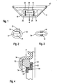
- a vehicle steering wheel having a steering wheel rim 10, spokes 12 and a hub plate 14.
- a gas bag module 16 attached in the area of the hub plate 14 is directly on the hub plate 14 or not explicitly shown mounting plates a gas bag module 16 attached.
- the gas bag module 16 has a housing 18, in which a gas generator 20 and a gas bag 22, which is inflated by the generator 20, are housed.
- a hollow profile 24 is fastened to the housing 18, which is closed in cross-section and clamped between the upper side of the hub plate 14 and the rear side of the module 16.
- the hollow profile is shown in Figures 2 and 3 in various embodiments.
- the hollow profile is closed annular, so that a gap 26 between the back of the module and the hub plate 14 is sealed and gas that generated by the gas generator 20 and partially out of the module housing 18 back side, can not lead to large leakage losses, because the gas flow prevented by the hollow section 24 at the passage through the gap 26.
- the hollow profile is provided with a horn switch which is actuated when the module is moved in the direction of arrow A, i. is shifted in the direction of the axis of the steering wheel by the driver.
- a sensor or the like is attached thereto or the sensor is integrated in it.
- a contact surface 30 is fixed to the hollow profile 24 on the inside of a section (for example by gluing).
- the contact surface 30 is associated with a contact line 32.
- a contact surface 34 spaced from the contact surface 30 in the non-actuated state is also fastened with an associated line 36. If the module is moved in the direction of arrow A, the elastic hollow section 24 is compressed (see arrow in Figure 2), so that the contact surfaces 30, 34 touch each other and a circuit is closed, which leads to the activation of the horn.
- the hollow profile 24 has such elasticity that, after the horn operation, it returns the entire module 16 back to the unactuated position, i. the initial position presses. Additional return springs can therefore be omitted.
- the integration of the horn switch in the hollow profile can also be done as in Figure 3.
- the inside are at the opposite integrated upper and lower portions in the elastomeric contact bands 40, 42, for example by partial encapsulation, wherein the contact bands also come into contact by compressing the hollow section 24 together.
- the hollow profile is fastened on a rear projection 50 of the module housing 18.
- the hollow profile has a relatively massive portion 52 which has formed at its lower end the hollow profile section 54.
- the hollow profile has a semicircular shape.
- the contact surfaces are designated 56 and 58.
- An additional sealing ring 60 is mounted on the steering wheel side, wherein the ring has a circumferential wall 62, on the inside of a projection which acts on the one hand as a sealing lip 64 and on the other hand as a guide surface, because the sealing lip 64 moves in a displacement of the module in the direction of arrow A. down, along the inside of the wall 62, whereby the module receives a longitudinal guide.
- the hollow profile in the steering wheel according to the invention could also be arranged below a horn surface, which is not provided by the module, but is arranged laterally on the module. Also in this embodiment, the hollow profile would have the horn switch and provide for the provision of the switch.
Landscapes
- Engineering & Computer Science (AREA)
- Mechanical Engineering (AREA)
- Physics & Mathematics (AREA)
- Acoustics & Sound (AREA)
- Air Bags (AREA)
- Steering Controls (AREA)
Description
- Die Erfindung betrifft ein Gassackmodul nach dem Oberbegriff des Anspruchs 1. Darüber hinaus betrifft die Erfindung ein Fahrzeuglenkrad mit einem erfindungsgemäßen Gassackmodul.
- Gattungsgemäße Gassackmodule werden auch als "Floating horn-Module" bezeichnet, denn sie sind am Lenkrad axial verschieblich gelagert. Auf der Rückseite des Moduls ist üblicherweise ein erster Schaltkontakt und auf der Nabenplatte des Lenkrads ein zweiter Schaltkontakt angebracht, die bei Verschiebung des Moduls aus einer Ausgangsstellung in eine Stellung zur Hupenbetätigung einander berühren. Zur Rückstellung des Moduls ist rückseitig zwischen dem Modul und dem Lenkrad wenigstens eine Rückstellfeder vorgesehen.
- Die gattungsbildende WO 98/02337 A zeigt eine Schaltereinheit mit vier Schaltern, die zwischen einem Gassackmodul und einer unteren Platte eines Lenkrades angeordnet ist. Beim Verschieben des Gassackmoduls wird eine Hupe betätigt.
- In der GB-A-2 309 123 sind Schalter gezeigt, die an einem Bauteil angebracht sind, das einen Gasgenerator trägt. Bei einer Verschiebung des Bauteils in Nabenrichtung wird eine Hupe ausgelöst.
- Die Erfindung schafft ein Gassackmodul, das sich durch eine geräuscharme Schaltbetätigung und wenig Einzelteile sowie eine einfache Montage auszeichnet. Dies wird bei einem Gassackmodul mit den Merkmalen des Anspruchs 1 erreicht. Das erfindungsgemäße Gassackmodul hat keinen gewöhnlichen Schalter, sondern ein mit einem Hupenschalter ausgestattetes Hohlprofil, in dem beispielsweise Abschnitte elektrisch leitend sind, die beim Zusammendrücken des Hohlprofils miteinander in Kontakt kommen. Auch können beispielsweise im Inneren des Hohlprofils an gegenüberliegenden Abschnitten Kontaktleiter angebracht oder in das Hohlprofil integriert sein, die beim Zusammendrücken des Hohlprofils durch Verschiebung des Moduls miteinander in Kontakt kommen. Durch die Integration der Kontaktelemente in das Hohlprofil ergibt sich auch ein Korrosionsschutz. Die Anzahl der zu montierenden Einzelteile wird verringert, denn das Hohlprofil bildet üblicherweise samt des integrierten Hupenschalters ein Einzelteil. Noch eine weitere Funktion kann das Hohlprofil übernehmen: nämlich eine Dichtfunktion. Rückseitig sollte aus dem Modul möglichst kein Gas, das in dem im Modul untergebrachten Gasgenerator erzeugt wird, ausströmen können. Vielmehr soll das gesamte erzeugte Gas in den Gassack strömen. Es sind deshalb aufwendige Abdichtungen auf der Rückseite des Moduls angedacht worden, die durch das Hohlprofil ersetzt werden. Das Hohlprofil ist nämlich so am oder im Modul angeordnet, daß es einen Spalt, über den das Gas aus dem Modul ausströmen könnte, abdichtet. Zu diesem Zweck erstreckt sich das Hohlprofil vorzugsweise ringförmig geschlossen an der Rückseite des Moduls.
- Gemäß der bevorzugten Ausführungsform ist das Hohlprofil rückseitig am Modul angeordnet und so ausgebildet, daß es bestrebt ist, das Modul nach der Hupenbetätigung in eine Ausgangsstellung zurückzudrängen. Das bedeutet, das Hohlprofil übernimmt noch eine zusätzliche Funktion, indem es die bislang vorgesehene Rückstellfeder unterstützt oder, bevorzugt, vollständig ersetzt und allein die Rückstellung des Moduls gewährleistet.
- In dem Hohlprofil kann beispielsweise ein Sensor, der den Hupenschalter bildet, angeordnet sein. Kontakte können im Hohlprofil befestigt oder in das Profil integriert sein, wie vorstehend bereits erläutert.
- Das erfindungsgemäße Fahrzeuglenkrad hat einen Hupenschalter und insbesondere auch ein erfindungsgemäßes Gassackmodul. Zur Verringerung der zu montierenden Teile ist ein Hohlprofil als Elastomer mit dem Hupenschalter ausgestattet.
- Wenn das erfindungsgemäße Gassackmodul vorgesehen ist, ist zwischen dem Modul und dem Lenkrad das Hohlprofil angeordnet. Darüber hinaus kann am Hohlprofil eine Dichtlippe sein, die am Lenkrad anliegt und die Dichtwirkung verbessert.
- Eine andere Ausführungsform sieht vor, daß das Hohlprofil seitlich so geführt ist, daß eine Längsführung für das gesamte Modul geschaffen wird. Bei dieser Ausführungsform übernimmt das Hohlprofil eine weitere Funktion, nämlich eine Führungsfunktion in Längsrichtung, d.h. in Richtung der Achse des Lenkrads.
- Weitere Merkmale und Vorteile der Erfindung ergeben sich aus der nachfolgenden Beschreibung und aus den nachfolgenden Zeichnungen, auf die Bezug genommen wird. In den Zeichnungen zeigen:
- Figur 1 eine schematische Querschnittsansicht durch ein erfindungsgemäßes Fahrzeuglenkrad mit einem erfindungsgemäßen Gassackmodul,
- Figuren 2 und 3 Querschnittsansichten verschiedener Ausführungsformen des beim erfindungsgemäßen Fahrzeugmodul eingesetzten Hohlprofils; und
- Figur 4 eine vergrößerte Querschnittsansicht durch einen Abschnitt des erfindungsgemäßen Moduls und des Lenkrads im Bereich eines Hohlprofils.
- In Figur 1 ist ein Fahrzeuglenkrad dargestellt, das einen Lenkradkranz 10, Speichen 12 und eine Nabenplatte 14 aufweist. Im Bereich der Nabenplatte 14 ist direkt an der Nabenplatte 14 oder an nicht explizit gezeigten Befestigungsblechen ein Gassackmodul 16 befestigt. Das Gassackmodul 16 hat ein Gehäuse 18, in dem ein Gasgenerator 20 sowie ein Gassack 22, der vom Generator 20 aufgeblasen wird, untergebracht sind. Rückseitig ist am Gehäuse 18 ein Hohlprofil 24 befestigt, das im Querschnitt geschlossen ist und zwischen der Oberseite der Nabenplatte 14 und der Rückseite des Moduls 16 geklemmt wird. Das Hohlprofil ist in den Figuren 2 und 3 in verschiedenen Ausführungsformen dargestellt. Das Hohlprofil verläuft geschlossen ringförmig, so daß ein Spalt 26 zwischen der Rückseite des Moduls und der Nabenplatte 14 abgedichtet ist und Gas, das vom Gasgenerator 20 erzeugt und teilweise aus dem Modulgehäuse 18 rückseitig heraustritt, nicht zu großen Leckageverlusten führen kann, denn der Gasstrom wird durch das Hohlprofil 24 am Durchtritt durch den Spalt 26 gehindert.
- Das Hohlprofil ist mit einem Hupenschalter ausgestattet, der dann betätigt wird, wenn das Modul in Richtung des Pfeiles A, d.h. in Richtung der Achse des Lenkrades vom Fahrer verschoben wird.
- Im Hohlprofil 24 ist hierzu ein Sensor oder dergleichen befestigt oder der Sensor ist in es integriert. Gemäß Figur 2 ist innenseitig an einem Abschnitt eine Kontaktfläche 30 am Hohlprofil 24 befestigt (z.B. durch Kleben). Der Kontaktfläche 30 ist eine Kontaktleitung 32 zugeordnet. Im Inneren des Hohlprofils ist ferner eine von der Kontaktfläche 30 im nicht betätigten Zustand beabstandete Kontaktfläche 34 mit einer zugehörigen Leitung 36 befestigt. Wird das Modul in Richtung des Pfeiles A verschoben, wird das elastische Hohlprofil 24 zusammengedrückt (siehe Pfeil in Figur 2), so daß die Kontaktflächen 30, 34 einander berühren und ein Stromkreis geschlossen wird, was zur Aktivierung der Hupe führt.
- Das Hohlprofil 24 hat eine solche Elastizität, daß es nach der Hupenbetätigung das gesamte Modul 16 zurück in die unbetätigte Stellung, d.h. die Ausgangsstellung drückt. Zusätzliche Rückstellfedern können deshalb entfallen.
- Die Integration des Hupenschalters in das Hohlprofil kann auch wie in Figur 3 erfolgen. Bei dieser Ausführungsform sind innenseitig an den gegenüberliegenden oberen und unteren Abschnitten in das Elastomer Kontaktbänder 40, 42 integriert, z.B. durch teilweises Umspritzen, wobei die Kontaktbänder ebenfalls durch Zusammendrücken des Hohlprofils 24 miteinander in Kontakt kommen.
- Bei der Ausführungsform nach Figur 4 ist das Hohlprofil auf einem rückseitigen Vorsprung 50 des Modulgehäuses 18 befestigt. Das Hohlprofil hat einen relativ massiven Abschnitt 52, der an seinem unteren Ende den Hohlprofilabschnitt 54 angeformt hat. Das Hohlprofil hat dabei eine halbkreisförmige Gestalt. Die Kontaktflächen sind mit 56 und 58 bezeichnet. Ein zusätzlicher Dichtring 60 ist lenkradseitig befestigt, wobei der Ring eine umlaufende Wand 62 besitzt, an deren Innenseite ein Vorsprung, der einerseits als Dichtlippe 64 fungiert und andererseits als Führungsfläche, denn die Dichtlippe 64 bewegt sich bei einer Verschiebung des Moduls in Richtung des Pfeiles A nach unten, an der Innenseite der Wand 62 entlang, wodurch das Modul eine Längsführung erhält.
- Alternativ könnte das Hohlprofil beim erfindungsgemäßen Lenkrad auch unterhalb einer Hupenfläche angeordnet sein, die nicht durch das Modul bereitgestellt wird, sondern seitlich am Modul angeordnet ist. Auch bei dieser Ausführungsform würde das Hohlprofil den Hupenschalter aufweisen und für die Rückstellung des Schalters sorgen.
Claims (9)
- Gassackmodul, das in ein Lenkrad integriert und relativ zum Lenkrad zur Hupenbetätigung verschiebbar ist, mit
einem am Modul (16) vorgesehenen Hupenschalter, der bei Verschiebung des Moduls (16) in eine die Hupenaktivierung herbeiführende Schalterstellung überführt wird,
dadurch gekennzeichnet,
daß ein Hohlprofil aus Elastomer vorgesehen ist, das mit dem Hupenschalter ausgestattet ist und am Modul (16) anliegt, und
daß das Hohlprofil (24) so am oder im Modul (16) angeordnet ist, daß es einen Spalt (26), über den Gas von einem Gasgenerator (20) ausströmen könnte, abdichtet. - Gassackmodul nach Anspruch 1, dadurch gekennzeichnet, daß das Hohlprofil (24) rückseitig am Modul (16) angeordnet und so ausgebildet ist, daß es bestrebt ist, das Modul (16) nach der Hupenbetätigung in eine Ausgangsstellung zurückzudrängen.
- Gassackmodul nach Anspruch 2, dadurch gekennzeichnet, daß die Rückstellung des Moduls (16) in die Ausgangsstellung durch das Hohlprofil (24) erfolgt.
- Gassackmodul nach einem der vorhergehenden Ansprüche, dadurch gekennzeichnet, daß in dem Hohlprofil (24) ein Sensor, der den Hupenschalter bildet, angeordnet ist.
- Gassackmodul nach einem der vorhergehenden Ansprüche, dadurch gekennzeichnet, daß das Hohlprofil (24) mit Kontakten (30, 34; 40, 42; 56, 58) versehen ist, die am Hohlprofil (24) befestigt oder in es integriert sind.
- Fahrzeuglenkrad mit einem Hupenschalter und einem Gassackmodul nach einem der vorhergehenden Ansprüche, wobei ein Hohlprofil (24) aus Elastomer mit dem Hupenschalter ausgestattet ist.
- Fahrzeuglenkrad nach Anspruch 6, dadurch gekennzeichnet, daß das Hohlprofil (24) zwischen dem Modul und dem Lenkrad angeordnet ist.
- Fahrzeuglenkrad nach Anspruch 6 oder 7, dadurch gekennzeichnet, daß am Hohlprofil (24) eine Dichtlippe (64) vorgesehen ist.
- Fahrzeuglenkrad nach einem der Ansprüche 6 bis 8, dadurch gekennzeichnet, daß das Hohlprofil (24) seitlich so geführt ist, daß eine Längsführung für das Modul (16) geschaffen ist.
Applications Claiming Priority (2)
| Application Number | Priority Date | Filing Date | Title |
|---|---|---|---|
| DE20108596U | 2001-05-22 | ||
| DE20108596U DE20108596U1 (de) | 2001-05-22 | 2001-05-22 | Gassackmodul und Fahrzeuglenkrad mit Gassackmodul |
Publications (3)
| Publication Number | Publication Date |
|---|---|
| EP1260416A2 EP1260416A2 (de) | 2002-11-27 |
| EP1260416A3 EP1260416A3 (de) | 2005-02-02 |
| EP1260416B1 true EP1260416B1 (de) | 2006-09-27 |
Family
ID=7957207
Family Applications (1)
| Application Number | Title | Priority Date | Filing Date |
|---|---|---|---|
| EP02010266A Expired - Lifetime EP1260416B1 (de) | 2001-05-22 | 2002-05-17 | Gassackmodul und Fahrzeuglenkrad mit Gassackmodul |
Country Status (4)
| Country | Link |
|---|---|
| US (1) | US7111867B2 (de) |
| EP (1) | EP1260416B1 (de) |
| DE (2) | DE20108596U1 (de) |
| ES (1) | ES2271141T3 (de) |
Families Citing this family (6)
| Publication number | Priority date | Publication date | Assignee | Title |
|---|---|---|---|---|
| GB2403999A (en) * | 2003-07-14 | 2005-01-19 | Autoliv Dev | Vehicle horn |
| US7055854B2 (en) | 2004-03-03 | 2006-06-06 | Autoliv Asp, Inc. | Snap-in castanet airbag module for a vehicular steering wheel |
| US8398115B2 (en) | 2008-06-25 | 2013-03-19 | Autoliv Development Ab | Vehicle steering wheel |
| US9242614B2 (en) * | 2014-03-07 | 2016-01-26 | Autoliv Asp, Inc. | Airbag systems with energy-absorbing components |
| CN118457491B (zh) * | 2024-06-12 | 2024-12-17 | 苏州明远汽车零部件制造有限公司 | 一种强化接合处密封的安全气囊连接机构 |
| FR3167594A1 (fr) | 2024-10-18 | 2026-04-24 | Autoliv Development Ab | Interrupteur d’avertisseur sonore de volant de véhicule |
Family Cites Families (14)
| Publication number | Priority date | Publication date | Assignee | Title |
|---|---|---|---|---|
| JPH0592004U (ja) * | 1992-03-12 | 1993-12-14 | センサー・テクノロジー株式会社 | エアバッグモジュール |
| DE9205252U1 (de) | 1992-04-15 | 1992-06-17 | Keune & Lauber GmbH, 57319 Bad Berleburg | Kontakteinrichtung am Lenkrad eines Fahrzeugs |
| US5283404A (en) | 1992-05-27 | 1994-02-01 | Morton International, Inc. | Minimum float, serviceable center blow horn switch in driver side air bag module |
| DE4430588C2 (de) * | 1994-08-19 | 1999-02-25 | Petri Ag | Gassack (Airbag)-System für Kraftfahrzeuge |
| JPH08207783A (ja) * | 1994-12-07 | 1996-08-13 | Toyoda Gosei Co Ltd | ステアリングホイール |
| GB2309123A (en) * | 1996-01-15 | 1997-07-16 | Autoliv Dev | A steering wheel assembly |
| US5721409A (en) * | 1996-06-05 | 1998-02-24 | Morton International, Inc. | Electrically conductive thermoplastic coupler for fusing a horn switch backing plate to an airbag module cover |
| US5772239A (en) * | 1996-06-24 | 1998-06-30 | Takata, Inc. | Airbag sub-module having fabric envelope with horn switch |
| SE9602747L (sv) | 1996-07-11 | 1998-01-12 | Volvo Ab | Arrangemang vid fordonsratt |
| GB2325900B (en) | 1997-06-05 | 2001-04-18 | Autoliv Dev | Improvements in or relating to a steering wheel arrangement |
| DE29720139U1 (de) | 1997-11-13 | 1998-03-19 | TRW Automotive Safety Systems GmbH, 63743 Aschaffenburg | Abdeckkappe für einen Airbag |
| DE29802472U1 (de) * | 1998-02-13 | 1998-04-23 | TRW Automotive Safety Systems GmbH, 63743 Aschaffenburg | Lenkrad mit eingestecktem Airbagmodul |
| DE19908385C2 (de) * | 1999-02-26 | 2001-11-15 | Petri Ag | Kontaktprofil für die Hornauslösung |
| IT1308842B1 (it) * | 1999-09-24 | 2002-01-11 | Gallino Plasturgia S R L | Dispositivo di azionamento di avvisatore acustico per un volante diazionamento. |
-
2001
- 2001-05-22 DE DE20108596U patent/DE20108596U1/de not_active Expired - Lifetime
-
2002
- 2002-05-17 DE DE50208232T patent/DE50208232D1/de not_active Expired - Fee Related
- 2002-05-17 ES ES02010266T patent/ES2271141T3/es not_active Expired - Lifetime
- 2002-05-17 EP EP02010266A patent/EP1260416B1/de not_active Expired - Lifetime
- 2002-05-21 US US10/152,526 patent/US7111867B2/en not_active Expired - Fee Related
Also Published As
| Publication number | Publication date |
|---|---|
| ES2271141T3 (es) | 2007-04-16 |
| DE20108596U1 (de) | 2001-09-27 |
| DE50208232D1 (de) | 2006-11-09 |
| US7111867B2 (en) | 2006-09-26 |
| EP1260416A2 (de) | 2002-11-27 |
| US20020175505A1 (en) | 2002-11-28 |
| EP1260416A3 (de) | 2005-02-02 |
Similar Documents
| Publication | Publication Date | Title |
|---|---|---|
| DE69307187T2 (de) | Zentraler Hupenschalter in einem Luftsackmodul auf der Fahrerseite | |
| EP1426237B1 (de) | Bauteil zum Einbau in geringem Abstand unter der äusseren Karosseriehaut eines Kraftfahrzeuges im Fussgängeraufprallbereich | |
| DE4242157B4 (de) | Modulabdeckung für ein Airbagsystem | |
| EP1245462B1 (de) | Fahrzeuglenkrad | |
| DE10027240B4 (de) | Luftsackmodul für Kraftfahrzeuge | |
| DE19908385C2 (de) | Kontaktprofil für die Hornauslösung | |
| EP0882625A2 (de) | Airbag-Vorrichtung | |
| EP1260416B1 (de) | Gassackmodul und Fahrzeuglenkrad mit Gassackmodul | |
| DE4034539A1 (de) | Lenkrad mit luftsackvorrichtung | |
| DE20213908U1 (de) | Airbagmodul sowie Baugruppe aus einem Lenkrad und einem Airbagmodul | |
| DE2025735A1 (de) | Elektrischer Streifenschalter | |
| EP0932526A1 (de) | Verfahren zur sicherung eines fahrzeuginsassen und airbagmodul zur durchführung des verfahrens | |
| WO2011101086A1 (de) | Hupenaktivierungseinrichtung | |
| EP1393972B1 (de) | Schalteinrichtung für eine Fahrzeughupe | |
| DE10021142B4 (de) | Fahrzeug, insbesondere Kraftfahrzeug | |
| DE60132715T2 (de) | Airbag-modul mit hupenschalter | |
| DE69908578T2 (de) | Airbaganordnung | |
| DE20010543U1 (de) | Multifunktionslenkrad | |
| DE19736488A1 (de) | Fahrzeuginsassenschutzvorrichtung | |
| WO2018197168A1 (de) | Anzünderträger, baugruppe, gasgenerator sowie verfahren zur herstellung eines gasgenerators | |
| EP1790536B1 (de) | Fahrzeuglenkrad mit Airbag und gedämpftem Hupenschalter | |
| EP0968104B1 (de) | Anordnung zur hupbetätigung bei modulintegrierten lenkrädern | |
| DE19625722C2 (de) | Lenkrad mit schwimmend angeordnetem Airbagmodul | |
| EP1145922B1 (de) | Fahrzeuglenkrad mit verschieblich gelagertem Gassackmodul | |
| DE102008023004B4 (de) | Hupenaktivierungseinrichtung sowie Sicherheitseinrichtung mit einer solchen Hupenaktivierungseinrichtung |
Legal Events
| Date | Code | Title | Description |
|---|---|---|---|
| PUAI | Public reference made under article 153(3) epc to a published international application that has entered the european phase |
Free format text: ORIGINAL CODE: 0009012 |
|
| AK | Designated contracting states |
Kind code of ref document: A2 Designated state(s): AT BE CH CY DE DK ES FI FR GB GR IE IT LI LU MC NL PT SE TR |
|
| AX | Request for extension of the european patent |
Free format text: AL;LT;LV;MK;RO;SI |
|
| PUAL | Search report despatched |
Free format text: ORIGINAL CODE: 0009013 |
|
| AK | Designated contracting states |
Kind code of ref document: A3 Designated state(s): AT BE CH CY DE DK ES FI FR GB GR IE IT LI LU MC NL PT SE TR |
|
| AX | Request for extension of the european patent |
Extension state: AL LT LV MK RO SI |
|
| RIC1 | Information provided on ipc code assigned before grant |
Ipc: 7B 60Q 5/00 B Ipc: 7B 60R 21/20 A |
|
| 17P | Request for examination filed |
Effective date: 20050727 |
|
| AKX | Designation fees paid |
Designated state(s): DE ES FR IT |
|
| GRAP | Despatch of communication of intention to grant a patent |
Free format text: ORIGINAL CODE: EPIDOSNIGR1 |
|
| GRAS | Grant fee paid |
Free format text: ORIGINAL CODE: EPIDOSNIGR3 |
|
| GRAA | (expected) grant |
Free format text: ORIGINAL CODE: 0009210 |
|
| AK | Designated contracting states |
Kind code of ref document: B1 Designated state(s): DE ES FR IT |
|
| PG25 | Lapsed in a contracting state [announced via postgrant information from national office to epo] |
Ref country code: IT Free format text: LAPSE BECAUSE OF FAILURE TO SUBMIT A TRANSLATION OF THE DESCRIPTION OR TO PAY THE FEE WITHIN THE PRESCRIBED TIME-LIMIT;WARNING: LAPSES OF ITALIAN PATENTS WITH EFFECTIVE DATE BEFORE 2007 MAY HAVE OCCURRED AT ANY TIME BEFORE 2007. THE CORRECT EFFECTIVE DATE MAY BE DIFFERENT FROM THE ONE RECORDED. Effective date: 20060927 |
|
| RAP1 | Party data changed (applicant data changed or rights of an application transferred) |
Owner name: TRW AUTOMOTIVE SAFETY SYSTEMS GMBH |
|
| REF | Corresponds to: |
Ref document number: 50208232 Country of ref document: DE Date of ref document: 20061109 Kind code of ref document: P |
|
| ET | Fr: translation filed | ||
| REG | Reference to a national code |
Ref country code: ES Ref legal event code: FG2A Ref document number: 2271141 Country of ref document: ES Kind code of ref document: T3 |
|
| PGFP | Annual fee paid to national office [announced via postgrant information from national office to epo] |
Ref country code: ES Payment date: 20070522 Year of fee payment: 6 |
|
| PLBE | No opposition filed within time limit |
Free format text: ORIGINAL CODE: 0009261 |
|
| STAA | Information on the status of an ep patent application or granted ep patent |
Free format text: STATUS: NO OPPOSITION FILED WITHIN TIME LIMIT |
|
| 26N | No opposition filed |
Effective date: 20070628 |
|
| PGFP | Annual fee paid to national office [announced via postgrant information from national office to epo] |
Ref country code: IT Payment date: 20070528 Year of fee payment: 6 |
|
| PGFP | Annual fee paid to national office [announced via postgrant information from national office to epo] |
Ref country code: FR Payment date: 20070503 Year of fee payment: 6 |
|
| REG | Reference to a national code |
Ref country code: FR Ref legal event code: ST Effective date: 20090119 |
|
| PG25 | Lapsed in a contracting state [announced via postgrant information from national office to epo] |
Ref country code: FR Free format text: LAPSE BECAUSE OF NON-PAYMENT OF DUE FEES Effective date: 20080602 |
|
| REG | Reference to a national code |
Ref country code: ES Ref legal event code: FD2A Effective date: 20080519 |
|
| PG25 | Lapsed in a contracting state [announced via postgrant information from national office to epo] |
Ref country code: IT Free format text: LAPSE BECAUSE OF NON-PAYMENT OF DUE FEES Effective date: 20080517 |
|
| PGFP | Annual fee paid to national office [announced via postgrant information from national office to epo] |
Ref country code: DE Payment date: 20090514 Year of fee payment: 8 |
|
| PG25 | Lapsed in a contracting state [announced via postgrant information from national office to epo] |
Ref country code: ES Free format text: LAPSE BECAUSE OF NON-PAYMENT OF DUE FEES Effective date: 20080519 |
|
| PG25 | Lapsed in a contracting state [announced via postgrant information from national office to epo] |
Ref country code: DE Free format text: LAPSE BECAUSE OF NON-PAYMENT OF DUE FEES Effective date: 20101201 |