EP1263221A2 - Méthode et dispositif d'affichage d'au moins deux images dans une image entière - Google Patents
Méthode et dispositif d'affichage d'au moins deux images dans une image entière Download PDFInfo
- Publication number
- EP1263221A2 EP1263221A2 EP02011839A EP02011839A EP1263221A2 EP 1263221 A2 EP1263221 A2 EP 1263221A2 EP 02011839 A EP02011839 A EP 02011839A EP 02011839 A EP02011839 A EP 02011839A EP 1263221 A2 EP1263221 A2 EP 1263221A2
- Authority
- EP
- European Patent Office
- Prior art keywords
- image
- video signal
- signal
- overall
- image information
- Prior art date
- Legal status (The legal status is an assumption and is not a legal conclusion. Google has not performed a legal analysis and makes no representation as to the accuracy of the status listed.)
- Withdrawn
Links
Images


Classifications
-
- H—ELECTRICITY
- H04—ELECTRIC COMMUNICATION TECHNIQUE
- H04N—PICTORIAL COMMUNICATION, e.g. TELEVISION
- H04N5/00—Details of television systems
- H04N5/44—Receiver circuitry for the reception of television signals according to analogue transmission standards
- H04N5/445—Receiver circuitry for the reception of television signals according to analogue transmission standards for displaying additional information
- H04N5/45—Picture in picture, e.g. displaying simultaneously another television channel in a region of the screen
-
- G—PHYSICS
- G09—EDUCATION; CRYPTOGRAPHY; DISPLAY; ADVERTISING; SEALS
- G09G—ARRANGEMENTS OR CIRCUITS FOR CONTROL OF INDICATING DEVICES USING STATIC MEANS TO PRESENT VARIABLE INFORMATION
- G09G5/00—Control arrangements or circuits for visual indicators common to cathode-ray tube indicators and other visual indicators
-
- H—ELECTRICITY
- H04—ELECTRIC COMMUNICATION TECHNIQUE
- H04N—PICTORIAL COMMUNICATION, e.g. TELEVISION
- H04N21/00—Selective content distribution, e.g. interactive television or video on demand [VOD]
- H04N21/40—Client devices specifically adapted for the reception of or interaction with content, e.g. set-top-box [STB]; Operations thereof
- H04N21/43—Processing of content or additional data, e.g. demultiplexing additional data from a digital video stream; Elementary client operations, e.g. monitoring of home network or synchronising decoder's clock; Client middleware
- H04N21/431—Generation of visual interfaces for content selection or interaction; Content or additional data rendering
- H04N21/4312—Generation of visual interfaces for content selection or interaction; Content or additional data rendering involving specific graphical features, e.g. screen layout, special fonts or colors, blinking icons, highlights or animations
- H04N21/4316—Generation of visual interfaces for content selection or interaction; Content or additional data rendering involving specific graphical features, e.g. screen layout, special fonts or colors, blinking icons, highlights or animations for displaying supplemental content in a region of the screen, e.g. an advertisement in a separate window
-
- G—PHYSICS
- G09—EDUCATION; CRYPTOGRAPHY; DISPLAY; ADVERTISING; SEALS
- G09G—ARRANGEMENTS OR CIRCUITS FOR CONTROL OF INDICATING DEVICES USING STATIC MEANS TO PRESENT VARIABLE INFORMATION
- G09G2340/00—Aspects of display data processing
- G09G2340/10—Mixing of images, i.e. displayed pixel being the result of an operation, e.g. adding, on the corresponding input pixels
-
- G—PHYSICS
- G09—EDUCATION; CRYPTOGRAPHY; DISPLAY; ADVERTISING; SEALS
- G09G—ARRANGEMENTS OR CIRCUITS FOR CONTROL OF INDICATING DEVICES USING STATIC MEANS TO PRESENT VARIABLE INFORMATION
- G09G2340/00—Aspects of display data processing
- G09G2340/12—Overlay of images, i.e. displayed pixel being the result of switching between the corresponding input pixels
Definitions
- the present invention relates to a method for display an image of a first video channel and an image of a second video channel in an overall picture and a device to carry out such a procedure.
- a first video signal and a multiplexer supply second video signal, the first video signal Image information of a in a first active area of the Overall picture to be displayed first picture and the second video signal Image information one active in a second Contains area of the overall image to be displayed second image.
- the multiplexer forms in the known method the first and second video signals an output video signal, to display the overall picture using a conventional one Display device, for example a monitor, suitable is.
- the overall picture is built up line by line, that is, the image information adjacent pixels in the overall picture lie in time in the output signal following before. Accordingly, the first and second video signals contain Image information of adjacent pixels consecutively.
- the multiplexer for each pixel its image information in the output signal is included, a decision is made as to whether the pixel in the first or second active area of the overall image or is outside of these active areas. Is the pixel within the first active area, so the Multiplexer the first video signal, or the picture information this video signal to the output to form the output signal further.
- the multiplexer gives the second video signal to the exit, and the pixel is outside of the first and second active area, so the multiplexer a video signal for a background image to the output further.
- the successive values of the output signal which contains the information of the overall picture line by line, are thus dependent on the position of a pixel in the overall picture, the first or second video signal or the Taken video signal for the background image.
- the multiplexer Control signals are supplied that provide information regarding the position and dimensions of the active areas.
- the first and second active overlap or overlap Area so for deciding whether the image information for a pixel of the overlapping area the first or second video signal is taken, a priority signal that determines which of the video signals to display the pixels of the overlap area are used which of the two pictures is in the foreground and the other of the two pictures thus partially or completely covered.
- the priority signal can be displayed in two Images take two different values, with one Change of the priority signal that previously shown in the background Moves the image to the foreground.
- the known method only enables the representation of the Image information of one of the video signals in the overlap area.
- the aim of the present invention is to provide a method for Representation of a first and a second image in one Overall picture to provide a representation of Image information of the first and second video signals in allows the overlap area and in particular cross-fading from the first to the second image in the overlap area when changing the one in the foreground Image is possible.
- the inventive method for representing a first and a second image that at least partially overlap, in an overall picture provides a first video signal to display the first image in a first active area of the overall picture and a second video signal for display of the second image in a second active area of the overall picture.
- a first video signal to display the first image in a first active area of the overall picture
- a second video signal for display of the second image in a second active area of the overall picture.
- an output signal to represent the overall picture being for representation of pixels of the overlap area exclusively Image information of the third video signal is used become.
- the information regarding the position and dimensions of the first active area are preferably in a first Control signal included, the information regarding the Position and dimensions of the second active area are preferably contained in a second control signal and the information regarding the position and dimensions of the overlap area are preferably in a third Control signal included, these scatter signals at the Decision whether an image information of the first, second or third video signal mapped to the output signal is made on the basis of the control signals.
- the third video signal has top priority, i.e. image information for pixels of the overlap area always taken from the third video signal.
- a first embodiment provides for the first and second Add video signal together.
- In the overlap area result from pixels their image information from a superimposition of the image information of the first image and the second image result.
- a second embodiment provides for the addition of the first and second video signals, the first video signal with with a first weighting factor and the second video signal to weight a second weighting factor.
- the weighting factors can change over time and / or they can be a spatial change that is called one of the position of the pixel to be displayed subject to change in the overlap area.
- a temporal or spatial change in the weighting factors enables a temporal or spatial crossfading of the representation of the first image to the second image in the The overlapping area.
- the change over time is the weighting factor of one Video signal first one and changes over time Zero while the weighting factor of the other video signal changes from zero to one.
- the length of time within which the Transition takes place is chosen so that it is greater than the length of time within which the image information for a image or field to be displayed are transmitted, wherein the duration is preferably at least a few seconds, so a slower continuous for the human eye Transition from the representation of the image information of the one video signal for displaying the image information of the other video signal in the overlap area arises.
- the Overlap area in a grid for example a checkerboard Subdivide the grid and in the individual fields this grid alternately the image information of the first and the second video signal. This is achieved by weighting factors that depend on the Position of the pixel to be displayed in the overlap area take the value one or zero.
- the weighting factors may also be subject to change over time, which means that from displaying an image in the overlap area about the representation of the "checkerboard pattern" on the Representation of the image information of the other image in the overlap area can be faded.
- the present invention furthermore relates to a Device for providing an output signal for Representation of at least a first image of a first video signal and a second image of a second video signal serves in an overall picture, the two pictures at least partially overlap.
- the device has one first input for supplying a first video signal to display a first image in a first active Area of the overall picture and a second entrance for feeding a second video signal to represent a second Image in a second active area of the overall image.
- the device has a logic circuit with at least an adder for adding the first and second video signals to form a third video signal and one Multiplexing device, the first, second and third video signal are supplied and an output signal for the Overall picture provides on.
- the device is a first control signal, the Information regarding the position and dimensions of the first active area and a second control signal, the Information regarding the position and dimensions of the contains second active area, feedable, this Control signals either separate control inputs of the device or the device together with the image information containing video signals can be fed.
- This Control signals either separate control inputs of the device or the device together with the image information containing video signals can be fed.
- the assignment of the first, second and third video signals to the output signal in the multiplexing device depends on the control signals, the representation of the pixels of the Overlap area that from the first and second video signal formed third video signal is used.
- the adder a first multiplier for multiplying the first video signal with a first weighting factor and a second Multiplier for multiplying the second video signal upstream with a second weighting factor.
- Figure 1 schematically illustrates an overall picture, which in a displayable screen area G a first image M in a first active area A1 and a second image S in one has second active region A2, the first and second active area A1, A2 an overlap area A12 have, in which the first and second image M, S overlap.
- an overlap area A12 In the area outside the first and second active A background image B is shown in area A1, A2.
- Figure 2 shows schematically a first embodiment of a Device 110 according to the invention for generating a Image signal OUT, which is the image information of an overall image of the type shown in Figure 1 with at least two overlapping Total images M, S contains and that in a conventional Video display device for displaying the overall picture can be used.
- a Device 110 for generating a Image signal OUT, which is the image information of an overall image of the type shown in Figure 1 with at least two overlapping Total images M, S contains and that in a conventional Video display device for displaying the overall picture can be used.
- the device 110 is a first video signal VM that the Image information of the first in the first active area A1 shown image M contains, and a second video signal VS, the image information of the second active in the second Area A2 shown image contains S supplied.
- the picture from the output signal OUT is line by line built up, that is the image information of the in one Line of adjacent pixels and the image information the pixels are in lines one below the other contained in the output signal OUT successively in time.
- the first video signal VM and the second video signal VS contain the image information to represent the first Image M in the first active area A1 or for display of the second image S in the second active area A2 in a corresponding manner, successively in lines.
- the first video signal VM is a first control signal MS and the second video signal VS is a second control signal SS assigned the position and dimensions of the active Determine areas A1, A2 in the overall picture.
- Figure 3 shows schematically the time course of an example of such Control signals MS, SS with the frequency shown Overall picture, which is usually 50Hz, periodically are.
- the time period T in FIG. 3 denotes the time period within the image information for the line-by-line structure of an overall picture.
- Tz denotes the length of time within which the image information of a line is transmitted become.
- the time periods at which the control signals MS, SS in Figure 3 an upper signal level assume the time periods to those within the total duration T the image information for the pixels of the active Areas A1, A2 are transmitted.
- the temporal portion of the Sections that assume an upper signal level at the Duration Tz corresponds to the ratio of the width of the overall picture G to the width of the respectively active area A1 or A2.
- the number of sections MS, VS to which the control signals assume an upper signal level corresponds to per period the number of lines that make up each active Area is established.
- the first and second video signals VM, VS and their associated ones Control signals are fed to a multiplexing device MUX, which the output signal OUT from the first and second Video signal VM, VS composed.
- the control signals MS, SS, MSS can be separated from the multiplexing device MUX the video signals VM, VS containing the image information can be supplied, or the control signals MS, SS Multiplexing device MUX together with the video signals VM, VS are supplied, that is, the control signals MS, SS can be modulated onto the video signals VM, VS, one Then separation into video signals VM, VS and control signals MS, SS is carried out in the multiplexing device MUX. In which 2 are the video signals VM, VS and their associated control signals MS, SS of the multiplexing device MUX fed separately.
- a third video signal VMS is formed.
- This third video signal VMS contains the image information of the image MS in the overlap area A12.
- the a third control signal MSS is assigned to the third video signal VMS, which is shown by way of example in FIG. 3c and that from an AND operation of the first and second control signals MS, SS results.
- the third video signal VMS and its associated control signal MSS are also the multiplexing device MUX fed.
- the device 110 and the multiplexing device MUX Figure 2 is also a fourth video signal VB for illustration of the background image B supplied.
- the output signal OUT contains the image information of the in the overall picture, built up line by line, lying side by side Pixels successively in time.
- MUX is for each pixel of the output signal OUT overall picture based on the control signals MS, SS, MSS made a decision as to whether the pixel within the first active area A1, within of the second active area A2, within the overlap area A12 from the first and second active areas A1, A2 or outside of these ranges.
- the pixel to be displayed lies but not within the second active area A2 in the overlap area A12, the associated image information of the second video signal VS for the output signal OUT, and the pixel to be displayed is in the overlap area A12, so the associated image information the third video signal VMS for the output signal OUT accepted.
- the image information of the fourth image signal VB for the output signal OUT is the overlap area in the method according to the invention, a separate video signal VMS assigned that in the overlap area A12 contains image information to be displayed.
- the device according to FIG. 2 results in the image information the pixels of the overlap area A12 from an overlay the image information of the first video signal VM and of the second video signal VS.
- the third video signal owns top priority, that is, to display the pixels Image information is always in the overlap area A12 of the third video signal VMS used.
- Figure 4 shows a further embodiment of an inventive Device 120 for forming an output signal OUT from the first and second video signals VM, VS.
- the Adders ADD are a first multiplier in this embodiment MUL1, the first video signal VM with a first Weighting factor m1 multiplied, and a second multiplier MUL2, the second video signal VS with a multiplied second weighting factor m2, upstream.
- the weighting factors m1, m2 can assume fixed values or can vary in time and / or space, as follows is explained.
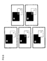
- Figure 5 shows a generated by means of an arrangement according to Figure 4 Overall picture, for the purpose of illustration one black first image M in the first active area A1 and a second white image S in the second active area A2 having.
- the weighting factors m1, m2 to represent the 5 are each 0.5, so that the Image information of the first image M and the second image S overlap in the overlap area A12 to form a gray image MS.
- Figure 6a illustrates another overall picture, in which the weighting factors m1, m2 are subject to a spatial change, that is, from the position of the one to be displayed Pixel in the overlap area A12.
- the Weighting factors m1, m2 are chosen so that they for successive pixels or a number of successive Alternating pixels of the overlap area A12 take the value one or zero, making a checkerboard Pattern is created in the overlap area A12, being in the fields where the first weighting factor m1 is one, the image information of the first video signal VM are shown, and in fields where the second weighting factor m2 is one, the image information of the second Video signal VS are shown.
- Figure 6b shows the time course of the first and second Weighting factor m1, m2 for that shown in Figure 6a Image.
- the signal MSS denotes the control signal for the third video signal, the time ranges in which the control signal MSS assumes an upper level, the temporal Marked areas where the image information each a line of the overlap area are transmitted.
- the time sections change, in which the first and second weighting factors m1, m2 each assume the value one or zero.
- FIG. 7 shows a further overall picture in which the first and second video signal VM, VS to form the third video signal VMS were added and weighted before addition.
- the value of the weighting factors is m1, m2 in this exemplary embodiment also from the position of the to be displayed Depending on the pixel in the overlap area A12. there applies that the first weighting factor m1 compared to the second Weighting factor m2 is greater, the further the Pixel in the upper left corner of the overlap area A12 lies and that the second weighting factor is m2 the first weighting factor m1 is greater, the further the pixel to be displayed in the lower right corner of the Overlap area A12.
- FIG 8 shows a further embodiment in which the Overlap area A12 as in the embodiment according to Figure 6 is divided into grids, with the weighting factors m1, m2 depending on the position of the grid areas in the Overlap area A12 vary.
- the weighting factors over time - namely over a period of time that spans multiple successive plots Single frames spans - to vary how is illustrated using the image sequence in FIG. 9.
- the first weighting factor m1 one, so that the Image information of the first image M in the overlap area A12 are shown and the first image M in the foreground stands. Starting from the first one in the foreground Image M takes place in the first overall image shown above a transition to the second one in the foreground Image S takes place at the last overall image shown below.
- the cross-fading takes place in a grid-shaped Pattern, starting with every second field of the grid the second weighting factor m2 increases and the first Weighting factor m1 decreases until the image information in these fields of the second image S is reproduced. Subsequently becomes the first weighting factor m1 in the rest Fields is reduced and the second weighting factor is m2 increases the image information of the reproduced second video signal VS or the second image is.
- the essential aspect of the method according to the invention is in that from the first and second video signals VM, that is the image information of the in the first active area A1, A2 contains the first image M, and from the second video signal VS, which contains the image information in the contains the second active area shown second image S, a third video signal VMS is formed which is like a third image channel treated in the formation of the output signal OUT becomes.
- the image information of the third video signal VMS are always shown in the foreground.
- Figure 10 shows another overall picture, in which a first Frame G around the first image M and a second frame F around that second image S is shown, the images M, S and the frames G, F surrounding the images partially overlap.
- Figure 11 shows an embodiment of an inventive Device 130 for providing an output signal OUT is suitable for displaying the overall picture.
- the device 130 are next to the first and second video signals VM, VS and the video signal VB for the background image B a video signal VG for the first frame G and a video signal VF for the second frame F supplied.
- a first multiplexer MUX1 supplied the output of the first multiplier MUL1 is connected downstream.
- the second video signal VS and the video signal VF for the second frame F one second multiplexer MUX2 supplied, the output of which second multiplier MUL2 is connected downstream.
- the first multiplexer MUX1 gives the depending on a control signal mux1 Image information of the first video signal VM or the video signal VG for the first frame G to its exit, where the control signal mux1 contains the information whether the Pixel to be displayed for the first active area A1 or belongs to the area of the first frame G.
- the second multiplexer MUX2 depending on a control signal mux2 the image information of the second video signal VS or the video signal VF for the first frame F on its Output continues, the control signal mux2 the information contains whether the pixel to be displayed corresponds to the second active one Area A1 or belongs to the area of the second frame F.
Landscapes
- Engineering & Computer Science (AREA)
- Multimedia (AREA)
- Signal Processing (AREA)
- Physics & Mathematics (AREA)
- Computer Hardware Design (AREA)
- General Physics & Mathematics (AREA)
- Theoretical Computer Science (AREA)
- Business, Economics & Management (AREA)
- Marketing (AREA)
- Studio Circuits (AREA)
- Television Systems (AREA)
- Transforming Electric Information Into Light Information (AREA)
Applications Claiming Priority (2)
| Application Number | Priority Date | Filing Date | Title |
|---|---|---|---|
| DE10126790A DE10126790A1 (de) | 2001-06-01 | 2001-06-01 | Verfahren und Vorrichtung zur Darstellung von wenigstens zwei Bildern in einem Gesamtbild |
| DE10126790 | 2001-06-01 |
Publications (2)
| Publication Number | Publication Date |
|---|---|
| EP1263221A2 true EP1263221A2 (fr) | 2002-12-04 |
| EP1263221A3 EP1263221A3 (fr) | 2004-03-31 |
Family
ID=7686936
Family Applications (1)
| Application Number | Title | Priority Date | Filing Date |
|---|---|---|---|
| EP02011839A Withdrawn EP1263221A3 (fr) | 2001-06-01 | 2002-05-28 | Méthode et dispositif d'affichage d'au moins deux images dans une image entière |
Country Status (3)
| Country | Link |
|---|---|
| US (1) | US7050112B2 (fr) |
| EP (1) | EP1263221A3 (fr) |
| DE (1) | DE10126790A1 (fr) |
Families Citing this family (19)
| Publication number | Priority date | Publication date | Assignee | Title |
|---|---|---|---|---|
| MXPA05005133A (es) | 2002-11-15 | 2005-07-22 | Thomson Licensing Sa | Metodo y aparato para composicion de subtitulos. |
| US8737810B2 (en) * | 2002-11-15 | 2014-05-27 | Thomson Licensing | Method and apparatus for cropping of subtitle elements |
| TWI282546B (en) * | 2004-04-02 | 2007-06-11 | Mstar Semiconductor Inc | Display controlling device capable of displaying multiple windows and related method |
| KR100609916B1 (ko) * | 2004-11-25 | 2006-08-08 | 삼성전자주식회사 | 디스플레이장치 및 그 제어방법 |
| JP4434973B2 (ja) * | 2005-01-24 | 2010-03-17 | 株式会社東芝 | 映像表示装置、映像合成配信装置、プログラム、システム及び方法 |
| US20070008338A1 (en) * | 2005-05-28 | 2007-01-11 | Young-Chan Kim | Display system, display apparatus, and method of controlling video source and display apparatus |
| JP4695474B2 (ja) * | 2005-09-21 | 2011-06-08 | 株式会社東芝 | 合成映像制御装置、合成映像制御方法およびプログラム |
| WO2007040045A1 (fr) * | 2005-09-30 | 2007-04-12 | Sharp Kabushiki Kaisha | Dispositif et méthode d’affichage d’image |
| US20090122188A1 (en) * | 2005-11-07 | 2009-05-14 | Toshiharu Hanaoka | Image display device and method |
| US9024966B2 (en) * | 2007-09-07 | 2015-05-05 | Qualcomm Incorporated | Video blending using time-averaged color keys |
| JP5116514B2 (ja) * | 2008-03-11 | 2013-01-09 | キヤノン株式会社 | 撮像装置および表示制御方法 |
| US20090309853A1 (en) * | 2008-06-13 | 2009-12-17 | Polyvision Corporation | Electronic whiteboard system and assembly with optical detection elements |
| US20100194789A1 (en) * | 2009-01-30 | 2010-08-05 | Craig Lin | Partial image update for electrophoretic displays |
| JP2011048040A (ja) * | 2009-08-26 | 2011-03-10 | Sony Corp | 映像信号処理装置、映像信号処理方法およびプログラム |
| WO2011149558A2 (fr) | 2010-05-28 | 2011-12-01 | Abelow Daniel H | Réalité alternée |
| TWI413960B (zh) * | 2010-10-12 | 2013-11-01 | Ite Tech Inc | 雙穩態光電顯示器及其驅動方法 |
| US9408958B2 (en) | 2010-12-17 | 2016-08-09 | Fresenius Medical Care Holdings, Inc. | User interfaces for dialysis devices |
| JP5427911B2 (ja) * | 2012-04-11 | 2014-02-26 | Eizo株式会社 | カーソル移動制御方法、コンピュータプログラム、カーソル移動制御装置及び画像表示システム |
| CN115152222A (zh) * | 2020-07-29 | 2022-10-04 | 谷歌有限责任公司 | 过度平滑渐进式图像 |
Family Cites Families (19)
| Publication number | Priority date | Publication date | Assignee | Title |
|---|---|---|---|---|
| US5594467A (en) * | 1989-12-06 | 1997-01-14 | Video Logic Ltd. | Computer based display system allowing mixing and windowing of graphics and video |
| JPH05323947A (ja) * | 1992-05-22 | 1993-12-07 | Pioneer Electron Corp | サブコードグラフィックス再生制御装置 |
| DE69315969T2 (de) * | 1992-12-15 | 1998-07-30 | Sun Microsystems Inc | Darstellung von Informationen in einem Anzeigesystem mit transparenten Fenstern |
| US5625764A (en) * | 1993-03-16 | 1997-04-29 | Matsushita Electric Industrial Co., Ltd. | Weighted average circuit using digit shifting |
| US5416529A (en) * | 1994-01-14 | 1995-05-16 | Immix | Method and system for digital video processing with combined downstream keyer and fade to black mixer |
| US5528290A (en) * | 1994-09-09 | 1996-06-18 | Xerox Corporation | Device for transcribing images on a board using a camera based board scanner |
| US5546518A (en) * | 1995-01-06 | 1996-08-13 | Microsoft Corporation | System and method for composing a display frame of multiple layered graphic sprites |
| US5896128A (en) * | 1995-05-03 | 1999-04-20 | Bell Communications Research, Inc. | System and method for associating multimedia objects for use in a video conferencing system |
| DE69635347T2 (de) * | 1995-07-10 | 2006-07-13 | Sarnoff Corp. | Verfahren und system zum wiedergeben und kombinieren von bildern |
| DE19546841C2 (de) | 1995-12-15 | 2000-06-15 | Sican Gmbh | Mehrfachoverlay mit einem Overlaycontroller |
| JPH10178564A (ja) * | 1996-10-17 | 1998-06-30 | Sharp Corp | パノラマ画像作成装置及び記録媒体 |
| US6912251B1 (en) * | 1998-09-25 | 2005-06-28 | Sarnoff Corporation | Frame-accurate seamless splicing of information streams |
| US6545685B1 (en) * | 1999-01-14 | 2003-04-08 | Silicon Graphics, Inc. | Method and system for efficient edge blending in high fidelity multichannel computer graphics displays |
| GB2348758B (en) | 1999-04-08 | 2003-10-29 | Ibm | Digital image processing |
| WO2001024518A1 (fr) * | 1999-09-25 | 2001-04-05 | Koninklijke Philips Electronics N.V. | Generation d'interface utilisateur |
| US6362854B1 (en) * | 1999-11-16 | 2002-03-26 | Media 100 Inc. | Effecting video transitions between video streams with a border |
| US6587155B1 (en) * | 1999-12-27 | 2003-07-01 | Lsi Logic Corporation | Fading of main video signal without affecting display of superimposed video signal |
| US6771304B1 (en) * | 1999-12-31 | 2004-08-03 | Stmicroelectronics, Inc. | Perspective correction device for panoramic digital camera |
| US20030122961A1 (en) * | 2001-12-28 | 2003-07-03 | Motorola, Inc. | Method for de-interlacing video information |
-
2001
- 2001-06-01 DE DE10126790A patent/DE10126790A1/de not_active Ceased
-
2002
- 2002-05-28 EP EP02011839A patent/EP1263221A3/fr not_active Withdrawn
- 2002-05-31 US US10/161,212 patent/US7050112B2/en not_active Expired - Fee Related
Also Published As
| Publication number | Publication date |
|---|---|
| US7050112B2 (en) | 2006-05-23 |
| EP1263221A3 (fr) | 2004-03-31 |
| DE10126790A1 (de) | 2003-01-02 |
| US20020196369A1 (en) | 2002-12-26 |
Similar Documents
| Publication | Publication Date | Title |
|---|---|---|
| EP1263221A2 (fr) | Méthode et dispositif d'affichage d'au moins deux images dans une image entière | |
| DE68926317T2 (de) | Bilderzeugungsgerät | |
| DE68928744T2 (de) | Verfahren zum senkrechten Filtern bei rasterabgetasteten Anzeigevorrichtungen | |
| DE60100645T2 (de) | Anzeigegerät zur Erzeugung von zwischenliegenden Graustufen und Verfahren zur Verarbeitung von Bildsignalen | |
| DE69522376T2 (de) | Verfahren und Vorrichtung zur graphischen Verarbeitung | |
| DE69835340T2 (de) | Verfahren zum mischen von bildern sowie anzeigevorrichtung | |
| DE19920812A1 (de) | Einrichtung zum Erzeugen einer interpolierten Videozeile | |
| EP0445336A1 (fr) | Méthode et dispositif de réduction du scintillement du bord d'une image de télévision | |
| DE3750862T2 (de) | Verarbeitung von Videobildsignalen. | |
| DE3842977C2 (de) | Mischeinrichtung für Videosignale | |
| DE10232372B3 (de) | Verfahren zur Interpolation eines Bildpunktes einer Zwischenzeile eines Halbbildes | |
| DE4143074A1 (de) | Verfahren und einrichtung zum umformatieren verschachtelter videodaten zur darstellung auf einem computer-ausgabedisplay | |
| DE10241353B4 (de) | Verfahren und Vorrichtung zum Umwandeln eines Farbbildes | |
| DE69215719T2 (de) | Digitaler Generator eines Randes um ein einem Hintergrund überlagertes Objekt | |
| EP2017784A2 (fr) | Procédé de traitement d'une suite d'images à l'aide d'images vidéo successives destinées à l'amélioration de la résolution spatiale | |
| DE102009026983A1 (de) | Bildverarbeitungsverfahren mit einer Bewegungsschätzung und Bildverarbeitungsanordnung | |
| DE69835413T2 (de) | Verfahren und Vorrichtung zur Flimmerdetektion in Fernsehbildern | |
| DE3639733C2 (de) | Schaltungsanordnung zur Verschärfung vertikaler Bildfeinheiten in einem Zeilensprung-Videosignalgemisch | |
| DE10327576A1 (de) | Verfahren und Vorrichtung zur bewegungsvektorgestützten Bildpunktinterpolation | |
| DE69825125T2 (de) | Verfahren und Vorrichtung zur Bildformatumwandlung | |
| DE102005063072B4 (de) | Verfahren und Vorrichtung zur Zwischenzeileninterpolation | |
| WO1996036175A1 (fr) | Procede et dispositif pour le traitement d'une image video | |
| DE69126478T2 (de) | Videosignalerzeugung | |
| DE19649651C1 (de) | Verfahren und Schaltungsanordnung zum Erzeugen einer Folge von progressiven Bildern | |
| EP1018264B1 (fr) | Procede et dispositif pour la production de cadres autour d'images video |
Legal Events
| Date | Code | Title | Description |
|---|---|---|---|
| PUAI | Public reference made under article 153(3) epc to a published international application that has entered the european phase |
Free format text: ORIGINAL CODE: 0009012 |
|
| AK | Designated contracting states |
Kind code of ref document: A2 Designated state(s): AT BE CH CY DE DK ES FI FR GB GR IE IT LI LU MC NL PT SE TR |
|
| AX | Request for extension of the european patent |
Free format text: AL;LT;LV;MK;RO;SI |
|
| PUAL | Search report despatched |
Free format text: ORIGINAL CODE: 0009013 |
|
| AK | Designated contracting states |
Kind code of ref document: A3 Designated state(s): AT BE CH CY DE DK ES FI FR GB GR IE IT LI LU MC NL PT SE TR |
|
| AX | Request for extension of the european patent |
Extension state: AL LT LV MK RO SI |
|
| AKX | Designation fees paid | ||
| REG | Reference to a national code |
Ref country code: DE Ref legal event code: 8566 |
|
| STAA | Information on the status of an ep patent application or granted ep patent |
Free format text: STATUS: THE APPLICATION IS DEEMED TO BE WITHDRAWN |
|
| 18D | Application deemed to be withdrawn |
Effective date: 20041001 |