EP1264740B1 - Mechanismus zum Verhindern einer Rückwärtsbewegung eines Fahrzeugsteuerpedals - Google Patents
Mechanismus zum Verhindern einer Rückwärtsbewegung eines Fahrzeugsteuerpedals Download PDFInfo
- Publication number
- EP1264740B1 EP1264740B1 EP02011691A EP02011691A EP1264740B1 EP 1264740 B1 EP1264740 B1 EP 1264740B1 EP 02011691 A EP02011691 A EP 02011691A EP 02011691 A EP02011691 A EP 02011691A EP 1264740 B1 EP1264740 B1 EP 1264740B1
- Authority
- EP
- European Patent Office
- Prior art keywords
- cowl top
- pedal
- vehicle
- bracket
- section
- Prior art date
- Legal status (The legal status is an assumption and is not a legal conclusion. Google has not performed a legal analysis and makes no representation as to the accuracy of the status listed.)
- Expired - Lifetime
Links
Images


Classifications
-
- B—PERFORMING OPERATIONS; TRANSPORTING
- B60—VEHICLES IN GENERAL
- B60T—VEHICLE BRAKE CONTROL SYSTEMS OR PARTS THEREOF; BRAKE CONTROL SYSTEMS OR PARTS THEREOF, IN GENERAL; ARRANGEMENT OF BRAKING ELEMENTS ON VEHICLES IN GENERAL; PORTABLE DEVICES FOR PREVENTING UNWANTED MOVEMENT OF VEHICLES; VEHICLE MODIFICATIONS TO FACILITATE COOLING OF BRAKES
- B60T7/00—Brake-action initiating means
- B60T7/02—Brake-action initiating means for personal initiation
- B60T7/04—Brake-action initiating means for personal initiation foot actuated
- B60T7/06—Disposition of pedal
-
- G—PHYSICS
- G05—CONTROLLING; REGULATING
- G05G—CONTROL DEVICES OR SYSTEMS INSOFAR AS CHARACTERISED BY MECHANICAL FEATURES ONLY
- G05G1/00—Controlling members, e.g. knobs or handles; Assemblies or arrangements thereof; Indicating position of controlling members
- G05G1/30—Controlling members actuated by foot
- G05G1/32—Controlling members actuated by foot with means to prevent injury
-
- B—PERFORMING OPERATIONS; TRANSPORTING
- B60—VEHICLES IN GENERAL
- B60R—VEHICLES, VEHICLE FITTINGS, OR VEHICLE PARTS, NOT OTHERWISE PROVIDED FOR
- B60R21/00—Arrangements or fittings on vehicles for protecting or preventing injuries to occupants or pedestrians in case of accidents or other traffic risks
- B60R21/02—Occupant safety arrangements or fittings, e.g. crash pads
- B60R21/09—Control elements or operating handles movable from an operative to an out-of-the way position, e.g. pedals, switch knobs, window cranks
-
- B—PERFORMING OPERATIONS; TRANSPORTING
- B60—VEHICLES IN GENERAL
- B60T—VEHICLE BRAKE CONTROL SYSTEMS OR PARTS THEREOF; BRAKE CONTROL SYSTEMS OR PARTS THEREOF, IN GENERAL; ARRANGEMENT OF BRAKING ELEMENTS ON VEHICLES IN GENERAL; PORTABLE DEVICES FOR PREVENTING UNWANTED MOVEMENT OF VEHICLES; VEHICLE MODIFICATIONS TO FACILITATE COOLING OF BRAKES
- B60T7/00—Brake-action initiating means
- B60T7/02—Brake-action initiating means for personal initiation
- B60T7/04—Brake-action initiating means for personal initiation foot actuated
- B60T7/06—Disposition of pedal
- B60T7/065—Disposition of pedal with means to prevent injuries in case of collision
-
- Y—GENERAL TAGGING OF NEW TECHNOLOGICAL DEVELOPMENTS; GENERAL TAGGING OF CROSS-SECTIONAL TECHNOLOGIES SPANNING OVER SEVERAL SECTIONS OF THE IPC; TECHNICAL SUBJECTS COVERED BY FORMER USPC CROSS-REFERENCE ART COLLECTIONS [XRACs] AND DIGESTS
- Y10—TECHNICAL SUBJECTS COVERED BY FORMER USPC
- Y10T—TECHNICAL SUBJECTS COVERED BY FORMER US CLASSIFICATION
- Y10T74/00—Machine element or mechanism
- Y10T74/20—Control lever and linkage systems
- Y10T74/20528—Foot operated
-
- Y—GENERAL TAGGING OF NEW TECHNOLOGICAL DEVELOPMENTS; GENERAL TAGGING OF CROSS-SECTIONAL TECHNOLOGIES SPANNING OVER SEVERAL SECTIONS OF THE IPC; TECHNICAL SUBJECTS COVERED BY FORMER USPC CROSS-REFERENCE ART COLLECTIONS [XRACs] AND DIGESTS
- Y10—TECHNICAL SUBJECTS COVERED BY FORMER USPC
- Y10T—TECHNICAL SUBJECTS COVERED BY FORMER US CLASSIFICATION
- Y10T74/00—Machine element or mechanism
- Y10T74/20—Control lever and linkage systems
- Y10T74/20576—Elements
- Y10T74/20888—Pedals
Definitions
- This invention relates to a rearward displacement prevention mechanism for a vehicle control pedal that moves toward the inner side of a vehicle compartment when impact load is applied to the front of the vehicle.
- Japanese Laid-Open Patent Publication (Kokai) No. 10-278760 has proposed a mechanism that prevents reward movement of a vehicle control pedal, which is constructed such that a rear end of a pedal bracket supporting the control pedal such that the control pedal is capable of pivotting is connected to a vehicle compartment side of a dash panel that separates an engine room and a vehicle compartment from each other, a rear end of the pedal bracket is mounted on a cowl top panel disposed at the upper side of the dash panel via a releasing mechanism.
- the dash panel is moved toward the inner side of the vehicle compartment due to impact load, the rear end of the pedal bracket is released from the cowl top panel by the releasing mechanism to inhibit rearward movement of the control pedal.
- Such a mechanism has a problem in that the moving direction of the rear end of the pedal bracket released from the cowl top is irregular.
- a releasing mechanism that has a guide member provided in a vehicle body component member disposed at an inner position in a vehicle compartment than a pedal bracket and that guides the pedal bracket, having been released from a cowl top panel, to a lower position when a dash panel is moved (rearward) to the inner side of the vehicle compartment due to an impact load applied to the vehicle.
- the releasing mechanism may not function in the case where the cowl top panel and the dash panel are moved toward the rear of the vehicle at the same time, i.e. in the case where the cowl top panel and the dash panel are displaced relatively to each other by only a small amount.
- JP-A-11-59351 discloses a vehicle pedal displacement control structure in which the movement of the pedal support is regulated by the pressing means.
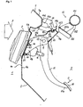
- a rearward displacement prevention mechanism in FIG. 1 is applied to a brake pedal 11 as a suspended control pedal.
- the rearward displacement prevention mechanism comprises a metal dash panel 5 that separates an engine room 1 and a vehicle compartment 3 from each other in a vehicle, a metal cowl top panel (cowl top section) 7 disposed at the upper side of the dash panel 5, a mounting bracket (cowl top section) 14 that is joined to a vehicle compartment side of the cowl top panel 7, a metal pedal bracket 9 that supports the brake pedal 11 such that the brake pedal 11 is capable of freely pivotting, and a regulating device 15 that is provided inside the vehicle compartment 3 such that it is opposed to the mounting bracket 14.
- the dash panel 5 extending in the direction of the vehicle width has an upper edge 5A thereof welded to a lower edge 7A of the cowl top panel 7 and has a lower edge thereof (not shown in the drawing), welded to a component member such as a floor panel (not shown in the drawing), of a vehicle body.
- a brake booster 2 is disposed in the engine room 1.
- the brake booster 2 is provided with a plurality of mounting bolts 22 that are designed to project into the vehicle compartment 3 through the dash panel 5 when the brake booster 2 is brought into contact with the dash panel 5.
- the bolts 22 fasten a flange portion 93 that is formed at a front end 9a of the pedal bracket 9.
- the brake booster 2 is mounted on a surface 5b at the engine room side of the dash panel 5 and the pedal bracket 9 is mounted on a surface 5a at the vehicle compartment side of the dash panel 5.
- the pedal bracket 9 is constructed to have a U-shaped section from the front end 9a to a central part 9c thereof, and is mounted on the dash panel 5 such that an opening of the U-shaped section is positioned in a lower place in FIG. 1.
- the pedal bracket 9 is also constructed to have a bag-shaped section at a rear end 9b where an upper panel 90 and a lower panel 91 are joined together.
- a base end 11a of the brake pedal 11 is supported on side walls of the pedal bracket 9, which are opposed to each other in the direction of the vehicle width, such that the brake pedal 11 is capable of freely pivotting about a pin 12.
- An operating rod 4 of the brake booster 2 is connected to the base end 11a of the brake pedal 11 by the pin12.
- the mounting bracket 14 is formed of a plate having a U-shaped section, and has a base end 14b thereof joined to a surface 7a at the vehicle compartment side of the cowl top panel 7.
- the mounting bracket 14 is formed with a wall-shaped contact surface 14a that is opposed to the regulating device 15.
- the mounting bracket 14 is formed with a cavity 14b from the center to the base end 14b thereof, so that the mounting bracket 14 can easily be collapsed.
- the rear end 9b of the pedal bracket 9 is mounted on the mounting bracket 14 via a releasing mechanism 13.
- the releasing mechanism comprises a release opening 20 formed in the upper panel 90, and a pin 17.
- the pin 17 comprises a shaft portion 17a and a pin head 17b that has a larger diameter than the shaft portion 17a.
- the release opening 20 extends in a direction in which the pedal bracket 9 moves as indicated by an arrow A.
- the opening 20 has an end 20a thereof positioned at the side of the regulating device 15 and is slightly larger than the shaft portion 17a, and an end 20b thereof having a size enough for the pin head 17b to pass through.
- the pin 17 goes through a mounting portion 14c of the mounting bracket 14 opposed to the upper panel 90 and the end 20a of the release opening 20.
- a shaft release member 19 such as an E ring
- the rear end 9b of the pedal bracket 9 is held on the mounting bracket 14 such that it is capable of being released from the mounting bracket 14.
- reference numeral 18 denotes a washer that is disposed between the floor panel 90 and the pin head 17b.
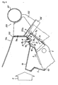
- the regulating device 15 comprises a cylindrical deck cross member 151 as a vehicle body component member extending in the direction of the vehicle width (vertical direction in FIG. 2), and a regulating member 152 that is integrated with the deck cross member 151 by welding or the like.
- the reason why the regulating member 152 is integrated with the deck cross member 151 is that the deck cross member 151 has a high stiffness since both ends thereof, not shown, positioned in the direction of the vehicle width are welded to the cowl top panel 7 and a front pillar, not shown.
- the deck cross member 151 is disposed at a slightly upper position than the center of the mounting bracket 14 such that it is opposed to the cowl top panel 7 and the mounting bracket 14.
- the regulating member 152 is formed with a regulating section 153 that is capable of being brought into contact with a contact surface 14a of the mounting bracket 14 moving toward the inner side of the vehicle compartment 3 due to an impact load F applied from the front of the vehicle, and a guiding section 155 that guides the rear end 9b of the pedal bracket 9 released from the mounting bracket 14 toward a lower place in FIG. 2, which corresponds to the lower part of the vehicle.
- the impact load F is an impact force that is applied to the front of the vehicle when the front of the vehicle collides with something.
- the regulating section 153 extends in the direction of the vehicle width, and a base end thereof has a U-shaped section.
- the regulating section 153 is disposed at such a position as to be brought into oblique contact with the contact surface 14a from above. Due to the integration with the deck cross member 151, the regulating section 153 has a higher stiffness than the mounting bracket 14.
- the regulating section 153 is preferably disposed on the track of the mounting bracket 14, i.e. the track of the contact surface 14 when the impact load F is applied to the front of the vehicle.
- the guiding section 155 has a U-shaped section, and comprises a flat inclined guide surface 155a that is obliquely inclined downward to the right from a position close to the regulating section 153.
- the regulating section 153 and the guiding section 155 are formed in the regulating member 152 integrated with the deck cross member 151, the regulating section 153 and the guiding section 155 may be provided as separate component parts in the deck cross member 151 or similar vehicle body component member.
- the guiding section 155 has the flat inclined guide surface 155a, the guide surface 155a may be formed as an arc extending from the regulating member 153 toward the dash panel 5.
- the contact surface 14a of the mounting bracket 14 is brought into contact with the regulating section 153 of the regulating device 15, which is provided inside the vehicle compartment 3 to be opposed to the cowl top panel 7. If a load applied to the mounting bracket 14 on this occasion is greater than the limit of the mounting bracket 14, the mounting bracket 14 is collapsed as a result of the contact with the regulating member 153, and if not, the mounting bracket 14 inhibits the cowl top panel 7 from moving toward the inner side of the vehicle compartment 3.
- the pin 17 of the releasing mechanism 13 is fixed, and thus, the pedal bracket 9 integrated with the dash panel 5 moves toward the inner side of the vehicle compartment 3 as indicated by an alternate long and short dash line in FIG. 2, so that the mounting bracket 14 and the dash panel 5 are displaced relatively to each other.
- the pin head 17b is positioned at the end 20b of the release opening 20 as shown in FIG. 4 due to the movement of the pedal bracket 9, the rear end 9b of the pedal bracket 9 is surely released from the mounting bracket 14 since the force for holding the pedal bracket 9 is lost.
- the released rear end 9b moves toward the inner side of the vehicle compartment 3 while lowering as indicated by an arrow B in FIG.
- FIG. 5 illustrates a rearward displacement prevention mechanism for a control pedal according to a second embodiment of the present invention.
- the second embodiment is characterized in that the rear end 9b of the pedal bracket 9 supporting the brake pedal 11 such that the pedal bracket 11 is capable of freely pivotting is mounted at the vehicle compartment side of a cowl top panel 70 via the releasing mechanism 13, and a regulating device 25 is provided inside a vehicle compartment 3 to be opposed to the cowl to panel 70.
- the second embodiment is different from the first embodiment shown in FIG. 1 in the shapes of the cowl top panel 70 and the regulating device 25 and in that there is not provided the mounting bracket 14.
- the cowl top panel 70 extends in the direction of the vehicle width, and has a lower end 70A thereof welded to the upper edge 5A of a dash panel 5 on which are commonly fastened a brake booster 2 and the front end 9a of the pedal bracket 9, so that the cowl top panel 70 is integrated with the dash panel 5.
- the cowl top panel 70 is formed with an expanding portion 70a that projects into the vehicle compartment 3.
- the rear end 9b of the pedal bracket 9 is mounted on a mounting portion 70c of the expanding portion 70a opposed to the upper panel 90 via the releasing mechanism 13.
- the release opening 20 constituting the releasing mechanism 13 is formed in the mounting portion 70c, and the pin 17 is mounted on the shaft release member 19 from the expanding section 70a through the mounting portion 70c and the end 20a of the release opening 20.
- the releasing mechanism 13 holds the rear end 9b of the pedal bracket 9 on the cowl top panel 70 such that the rear end 9b is capable of being released from the cowl top panel 70.
- the regulating device 25 comprises the deck cross member 151 disposed at an inner position in the vehicle compartment 3 than an end face 70b of the expanding portion 70a, and a regulating member 252 that is integrated with the deck cross member 151 by welding or the like.
- the reason why the regulating member 252 is integrated with the deck cross member 151 is that the deck cross member 151 has a high stiffness since both ends thereof, not shown, positioned in the direction of the vehicle width are welded to the cowl top panel 70 and a front pillar, not shown.
- the deck cross member 151 is opposed to the expanding portion 70a.
- the regulating member 252 is formed with a regulating section 253 that is capable of being brought into contact with the end face 70b of the expanding portion 70a moving toward the inner side of the vehicle compartment 3 due to an impact load F applied to the front of the vehicle, and a guiding section 255 that guides the rear end 9b of the pedal bracket 9 released from the expanding portion 70a to a lower position in FIG. 5, which corresponds to the lower part of the vehicle.
- the regulating section 253 is one surface of a U-shaped section extending in the direction of the vehicle width, and is disposed at such a position as to be brought into frontal contact with the end face 70b. Due to the integration with the deck cross member 151, the regulating section 253 has a higher stiffness than the expanding portion 70a. In order that the regulating section 253 is surely brought into contact with the end face 70b, the regulating section 253 is preferably disposed on the track of the expanding portion 70a, i.e. the track of the expanding portion 70a when the impact force F is applied to the front of the vehicle.
- the guiding section 255 has a U-shaped section, and comprises a flat inclined guide surface 255a that is inclined obliquely downward to the right from a position close to the regulating section 253 in FIG. 5.
- the regulating section 253 and the guiding section 255 are formed in the regulating member 252 integrated with the deck cross member 151, the regulating section 253 and the guiding section 255 may be provided as separate component parts in the deck cross member 151 or similar vehicle body component part.
- the guiding section 255 has the flat inclined guide surface 255a, the guide surface 255a be formed as an arc extending from the regulating member 253 toward the dash panel 5.
- the end face 70b of the cowl top panel 70 is brought into contact with the regulating section 253 of the regulating device 25, which is provided inside the vehicle compartment 3 to be opposed to the expanding portion 70a of the cowl top panel 70. If a load applied to the end face 70b on this occasion is greater than the limit of the expanding portion 70a, the expanding portion 70a is collapsed as a result of the contact with the regulating member 253, and if not, the expanding portion 70a inhibits the cowl top panel 70 from moving toward the inner side of the vehicle compartment 3.
- the pin 17 of the releasing mechanism 13 is fixed, and thus, the pedal bracket 9 integrated with the dash panel 5 moves toward the inner side of the vehicle compartment 3 as indicated by an alternate long and short dash line in FIG. 6, so that the expanding portion 70a and the dash panel 5 are displaced relatively to each other.
- the pin head 17b is positioned at the end 20b of the release opening 20 as shown in FIG. 4 due to the movement of the pedal bracket 9, the rear end 9b of the pedal bracket 9 is surely released from the expanding portion 70a since the force for holding the pedal bracket 9 is lost.
- the released rear end 9b moves toward the inner side of the vehicle compartment 3 while lowering as indicated by an arrow B in FIG.
- the releasing mechanism in the above-described embodiments utilizes the relative displacement of the dash panel 5 and the cowl top panel 7, and therefore, even if only the dash panel 5 moves toward the inner side of the vehicle compartment 3 due to the impact load F, the pin 17 is fixed on the mounting bracket 14 or the mounting portion 70c of the expanding portion 70a.
- the pin head 17b is positioned at the end 20b of the release opening 20 as a result of the movement of the pedal bracket 9
- the rear end 9b of the pedal bracket 9 can be surely released from the mounting bracket 14 or the expanding portion 70a.
- the brake pedal 11 is used as a control pedal, it goes without saying that the present invention may be applied to a rearward displacement prevention mechanism that prevents a clutch pedal that engages and disengages a clutch in the case where a transmission installed in a vehicle is a manual transmission from moving torward the inner side of a vehicle.
- the operating rod 4 of the brake booster 2 is directly connected to the brake pedal 11, a brake pedal for use in side braking may be used as the brake pedal 11.
Landscapes
- Engineering & Computer Science (AREA)
- Mechanical Engineering (AREA)
- Transportation (AREA)
- Physics & Mathematics (AREA)
- General Physics & Mathematics (AREA)
- Automation & Control Theory (AREA)
- Body Structure For Vehicles (AREA)
- Braking Elements And Transmission Devices (AREA)
- Mechanical Control Devices (AREA)
Claims (8)
- Mechanismus zur Verhinderung einer Rückwärtsbewegung eines Betätigungspedals, mit:einer Trennwand (5), die einen Motorraum (1) und einen Fahrgastraum (3) in einem Fahrzeug voneinander trennt;einem oberen Abdeckabschnitt, der an einer oberen Seite der Trennwand angeordnet ist;einem Pedalträger (9), der mit seinem vorderen Ende mit einer Fahrgastraumseite der Trennwand verbunden ist, und das Betätigungspedal (11) so lagert, dass das Betätigungspedal schwenken kann;einem Freigabemechanismus, der zwischen dem oberen Abdeckabschnitt und dem hinteren Ende des Pedalträgers vorgesehen und geeignet ist, das hintere Ende des Pedalträgers von dem oberen Abdeckabschnitt freizugeben bzw. zu lösen; undeiner Steuerungsvorrichtung (152), die innerhalb des Fahrgastraums vorgesehen ist und dem oberen Abdeckabschnitt gegenüberliegt, dadurch gekennzeichnet, dassim Falle einer auf die Vorderseite des Fahrzeugs ausgeübten Stoßbelastung sich die Trennwand rückwärts bewegt, und der Pedalträger von dem oberen Abdeckabschnitt durch den Kontakt des oberen Abdeckabschnittes mit der Steuerungsvorrichtung freigegeben bzw. gelöst wird, wobei der Kontakt eine relative Verschiebung zwischen dem oberen Abdeckabschnitt und dem Pedalträger bewirkt.
- Mechanismus zur Verhinderung einer Rückwärtsbewegung eines Betätigungspedals nach Anspruch 1, wobei:der obere Abdeckabschnitt ein oberes Abdeckblech (7) ist, und der Freigabemechanismus auf den Kontakt des oberen Abdeckbleches (7) mit der Steuerungsvorrichtung (152) reagiert, indem er das hintere Ende des Pedalträgers (9) von dem oberen Abdeckblech freigibt bzw. löst.
- Mechanismus zur Verhinderung einer Rückwärtsbewegung eines Betätigungspedals nach Anspruch 1, wobei:der obere Abdeckabschnitt ein oberes Abdeckblech (7) und einen Befestigungsträger (14) aufweist, der auf einer Fahrgastraumseite des oberen Abdeckbleches (7) vorgesehen ist, und der Freigabemechanismus auf den Kontakt des Befestigungsträgers (14) mit der Steuerungsvorrichtung (152) reagiert, indem er das hintere Ende des Pedalträgers (9) von dem Befestigungsträger (14) freigibt bzw. löst.
- Mechanismus zur Verhinderung einer Rückwärtsbewegung eines Betätigungspedals nach Anspruch 3, wobei:eine Aussparung (14b) in dem Befestigungsträger ausgebildet ist.
- Mechanismus zur Verhinderung einer Rückwärtsbewegung eines Betätigungspedals nach einem der Ansprüche 1 bis 4, wobei:die Steuerungsvorrichtung ein Element der Fahrzeugkarosseriekomponente (151) aufweist, das an einer in dem Fahrgastraum weiter innen liegenden Position als der obere Abdeckabschnitt angeordnet ist, um sich in einer Fahrzeugbreitenrichtung zu erstrecken, einen Steuerungsabschnitt (153) aufweist, der in dem Element der Fahrzeugkarosseriekomponente vorgesehen ist und mit dem oberen Abdeckabschnitt, der sich aufgrund einer Stoßbelastung in Richtung der Innenseite des Fahrgastraums bewegt in Kontakt gebracht wird, und einen Führungsabschnitt (155) aufweist, der in dem Element der Fahrzeugkarosseriekomponente vorgesehen ist, um den von dem oberen Abdeckabschnitt durch die Betätigung des Freigabemechanismus freigegebenen bzw. gelösten Pedalträger zu führen.
- Mechanismus zur Verhinderung einer Rückwärtsbewegung eines Betätigungspedals nach Anspruch 5, wobei:die Steuerungsvorrichtung an einer solchen Position angeordnet ist, dass sie mit dem Befestigungsträger (14) vor dem Führungsabschnitt der Steuerungsvorrichtung in Kontakt gebracht wird.
- Mechanismus zur Verhinderung einer Rückwärtsbewegung eines Betätigungspedals nach Anspruch 5 oder 6, wobei:der Führungsabschnitt (155) der Steuerungsvorrichtung einen U-förmigen Abschnitt besitzt und eine geneigte Führungsfläche (155a) aufweist, die schräg nach unten geneigt ist.
- Mechanismus zur Verhinderung einer Rückwärtsbewegung eines Betätigungspedals nach einem der Ansprüche 3 bis 7, wobei:die Steuerungsvorrichtung auf einer Bewegungsbahn des Befestigungsträgers (14) angeordnet ist.
Applications Claiming Priority (2)
| Application Number | Priority Date | Filing Date | Title |
|---|---|---|---|
| JP2001173422A JP2002362339A (ja) | 2001-06-08 | 2001-06-08 | 操作ペダルの後退変位抑制機構 |
| JP2001173422 | 2001-06-08 |
Publications (3)
| Publication Number | Publication Date |
|---|---|
| EP1264740A2 EP1264740A2 (de) | 2002-12-11 |
| EP1264740A3 EP1264740A3 (de) | 2003-08-27 |
| EP1264740B1 true EP1264740B1 (de) | 2005-11-30 |
Family
ID=19014879
Family Applications (1)
| Application Number | Title | Priority Date | Filing Date |
|---|---|---|---|
| EP02011691A Expired - Lifetime EP1264740B1 (de) | 2001-06-08 | 2002-06-03 | Mechanismus zum Verhindern einer Rückwärtsbewegung eines Fahrzeugsteuerpedals |
Country Status (8)
| Country | Link |
|---|---|
| US (1) | US7066047B2 (de) |
| EP (1) | EP1264740B1 (de) |
| JP (1) | JP2002362339A (de) |
| KR (1) | KR100494328B1 (de) |
| CN (1) | CN1211227C (de) |
| DE (1) | DE60207635T2 (de) |
| MY (1) | MY134415A (de) |
| TW (1) | TW544415B (de) |
Families Citing this family (14)
| Publication number | Priority date | Publication date | Assignee | Title |
|---|---|---|---|---|
| JP4029800B2 (ja) * | 2003-08-26 | 2008-01-09 | マツダ株式会社 | 自動車のペダル支持構造 |
| KR100527758B1 (ko) | 2003-11-03 | 2005-11-10 | 현대자동차주식회사 | 자동차용 스티어링컬럼의 장착구조 |
| KR100552747B1 (ko) * | 2003-11-13 | 2006-02-20 | 현대자동차주식회사 | 자동차 브레이크페달의 발목 상해 방지구조 |
| EP1640229B1 (de) * | 2004-09-27 | 2007-01-24 | Mazda Motor Corporation | Fahrzeugpedalabstützung |
| WO2006038333A1 (ja) * | 2004-09-30 | 2006-04-13 | Fuji Jukogyo Kabushiki Kaisha | 車両用ブレーキ装置 |
| JP2006273023A (ja) * | 2005-03-28 | 2006-10-12 | Mazda Motor Corp | 自動車のペダル支持構造 |
| JP2006273024A (ja) * | 2005-03-28 | 2006-10-12 | Mazda Motor Corp | 自動車のペダル支持構造 |
| JP4797540B2 (ja) * | 2005-09-26 | 2011-10-19 | マツダ株式会社 | ペダルの後退防止構造 |
| JP4466659B2 (ja) * | 2007-02-19 | 2010-05-26 | トヨタ自動車株式会社 | 車両用ペダル支持構造 |
| ITTO20090441A1 (it) * | 2009-06-10 | 2010-12-11 | Sistemi Comandi Meccanici S C M S P A | Pedaliera di comando di un veicolo provvista di un meccanismo di sgancio. |
| JP4696216B2 (ja) * | 2009-06-16 | 2011-06-08 | 三菱自動車工業株式会社 | ペダル装置 |
| JP5872808B2 (ja) * | 2011-07-20 | 2016-03-01 | 三菱自動車工業株式会社 | ペダル装置 |
| KR101406644B1 (ko) * | 2012-08-30 | 2014-06-11 | 현대자동차주식회사 | 차량용 페달의 상해 방지장치 |
| US8985630B2 (en) * | 2013-07-19 | 2015-03-24 | GM Global Technology Operations LLC | Cradle assembly attachable to a vehicle |
Family Cites Families (16)
| Publication number | Priority date | Publication date | Assignee | Title |
|---|---|---|---|---|
| JP2798467B2 (ja) * | 1990-02-27 | 1998-09-17 | マツダ株式会社 | 自動車の車体前部構造及び車体組付方法 |
| DE19522398C1 (de) * | 1995-06-23 | 1996-12-19 | Daimler Benz Ag | Sicherheitsanordnung im Fußraum eines Kraftwagens |
| JP3267182B2 (ja) * | 1996-05-29 | 2002-03-18 | トヨタ自動車株式会社 | 車両用ペダル変位制御構造 |
| JPH10175492A (ja) * | 1996-12-18 | 1998-06-30 | Toyota Motor Corp | 車両用ペダル変位制御構造 |
| JPH10181637A (ja) * | 1996-12-25 | 1998-07-07 | Toyota Motor Corp | 車両用ペダル変位制御構造 |
| JPH10278460A (ja) | 1997-04-09 | 1998-10-20 | Toppan Printing Co Ltd | 複製防止物品、物品の真偽判別方法および物品の真偽判別装置 |
| JP3795180B2 (ja) * | 1997-04-10 | 2006-07-12 | 日産自動車株式会社 | 自動車のペダルブラケット取付構造 |
| JP3781864B2 (ja) * | 1997-04-21 | 2006-05-31 | 日産自動車株式会社 | 自動車のブレーキペダル装置 |
| JP4015226B2 (ja) * | 1997-05-13 | 2007-11-28 | 本田技研工業株式会社 | 自動車のブレーキペダル支持構造 |
| JP3125715B2 (ja) * | 1997-05-23 | 2001-01-22 | トヨタ自動車株式会社 | 車両用ペダル変位制御構造 |
| BR9803209A (pt) * | 1997-08-27 | 1999-10-13 | Scharwaechter Ed Gmbh | Conjunto de segurança para montagem de pedais em veículos automotores |
| JPH1159351A (ja) * | 1997-08-27 | 1999-03-02 | Toyota Motor Corp | 車両用ペダル変位制御構造 |
| JPH11139346A (ja) * | 1997-11-06 | 1999-05-25 | Toyota Motor Corp | 車両用ペダル変位制御構造 |
| JP3542709B2 (ja) * | 1998-01-13 | 2004-07-14 | 株式会社ヨロズ | 自動車のブレーキペダル装置 |
| JP3792465B2 (ja) * | 1999-07-02 | 2006-07-05 | 株式会社エフテック | 自動車のブレーキペダル装置 |
| KR100316950B1 (ko) * | 1999-08-10 | 2001-12-22 | 이계안 | 자동차의 브레이크페달 지지구조 |
-
2001
- 2001-06-08 JP JP2001173422A patent/JP2002362339A/ja active Pending
-
2002
- 2002-05-27 KR KR10-2002-0029150A patent/KR100494328B1/ko not_active Expired - Fee Related
- 2002-05-28 TW TW091111351A patent/TW544415B/zh active
- 2002-06-03 EP EP02011691A patent/EP1264740B1/de not_active Expired - Lifetime
- 2002-06-03 DE DE60207635T patent/DE60207635T2/de not_active Expired - Lifetime
- 2002-06-06 MY MYPI20022105A patent/MY134415A/en unknown
- 2002-06-07 CN CNB021227306A patent/CN1211227C/zh not_active Expired - Fee Related
- 2002-06-07 US US10/163,336 patent/US7066047B2/en not_active Expired - Fee Related
Also Published As
| Publication number | Publication date |
|---|---|
| DE60207635D1 (de) | 2006-01-05 |
| CN1390726A (zh) | 2003-01-15 |
| CN1211227C (zh) | 2005-07-20 |
| MY134415A (en) | 2007-12-31 |
| US7066047B2 (en) | 2006-06-27 |
| KR20020095080A (ko) | 2002-12-20 |
| KR100494328B1 (ko) | 2005-06-13 |
| JP2002362339A (ja) | 2002-12-18 |
| EP1264740A2 (de) | 2002-12-11 |
| DE60207635T2 (de) | 2006-07-13 |
| TW544415B (en) | 2003-08-01 |
| US20030000334A1 (en) | 2003-01-02 |
| EP1264740A3 (de) | 2003-08-27 |
Similar Documents
| Publication | Publication Date | Title |
|---|---|---|
| EP1264740B1 (de) | Mechanismus zum Verhindern einer Rückwärtsbewegung eines Fahrzeugsteuerpedals | |
| US6655489B2 (en) | Pedal displacement prevention structure for a vehicle and a vehicle thereof | |
| KR100302033B1 (ko) | 차량용페달변위제어구조 | |
| JP4221160B2 (ja) | 操作ペダルの後退変位抑制機構 | |
| US7111703B2 (en) | Vehicular pedal supporting structure | |
| EP0805080A2 (de) | Tragkonstruktion einer Fahrzeugpedalvorrichtung | |
| EP1738982B1 (de) | Vorrichtung zum Verhindern einer Rückwärtsbewegung eines Fahrzeugpedals | |
| JP3897216B2 (ja) | ペダル支持構造 | |
| JP3932702B2 (ja) | ペダルブラケットの構造 | |
| JP4106549B2 (ja) | ペダル支持構造 | |
| EP1038720A2 (de) | Pedalgehäuse für Fahrzeug | |
| JPH11268667A (ja) | 車両用ペダル変位制御構造 | |
| JP2003112614A (ja) | ブレーキペダルの取り付け構造 | |
| JP3804651B2 (ja) | 車両用ペダル変位制御構造 | |
| JP5052180B2 (ja) | 自動車用ペダル支持構造 | |
| JP3631418B2 (ja) | フットペダルの後退防止構造 | |
| JP2000264180A (ja) | 車両用ペダル取付構造 | |
| JP7803525B2 (ja) | 車両構造 | |
| JP6352229B2 (ja) | 車両用ペダル装置の後退防止装置 | |
| JPS6216387Y2 (de) | ||
| JP4360251B2 (ja) | トルクロッドの取付け構造 | |
| JP2004066853A (ja) | ブレーキペダルの支持構造 | |
| JPH10278760A (ja) | 自動車のペダルブラケット取付構造 | |
| JPH06255536A (ja) | 車体前部構造 | |
| JPH07165088A (ja) | 車両のステアリング支持装置およびその組み付け方法 |
Legal Events
| Date | Code | Title | Description |
|---|---|---|---|
| PUAI | Public reference made under article 153(3) epc to a published international application that has entered the european phase |
Free format text: ORIGINAL CODE: 0009012 |
|
| 17P | Request for examination filed |
Effective date: 20020703 |
|
| AK | Designated contracting states |
Kind code of ref document: A2 Designated state(s): AT BE CH CY DE DK ES FI FR GB GR IE IT LI LU MC NL PT SE TR |
|
| AX | Request for extension of the european patent |
Free format text: AL;LT;LV;MK;RO;SI |
|
| PUAL | Search report despatched |
Free format text: ORIGINAL CODE: 0009013 |
|
| AK | Designated contracting states |
Designated state(s): AT BE CH CY DE DK ES FI FR GB GR IE IT LI LU MC NL PT SE TR |
|
| AX | Request for extension of the european patent |
Extension state: AL LT LV MK RO SI |
|
| RAP1 | Party data changed (applicant data changed or rights of an application transferred) |
Owner name: MITSUBISHI JIDOSHA KOGYO KABUSHIKI KAISHA Owner name: MITSUBISHI JIDOSHA ENGINEERING KABUSHIKI KAISHA |
|
| AKX | Designation fees paid |
Designated state(s): DE FR GB |
|
| 17Q | First examination report despatched |
Effective date: 20040419 |
|
| GRAP | Despatch of communication of intention to grant a patent |
Free format text: ORIGINAL CODE: EPIDOSNIGR1 |
|
| GRAS | Grant fee paid |
Free format text: ORIGINAL CODE: EPIDOSNIGR3 |
|
| GRAA | (expected) grant |
Free format text: ORIGINAL CODE: 0009210 |
|
| AK | Designated contracting states |
Kind code of ref document: B1 Designated state(s): DE FR GB |
|
| REG | Reference to a national code |
Ref country code: GB Ref legal event code: FG4D |
|
| REF | Corresponds to: |
Ref document number: 60207635 Country of ref document: DE Date of ref document: 20060105 Kind code of ref document: P |
|
| ET | Fr: translation filed | ||
| PLBE | No opposition filed within time limit |
Free format text: ORIGINAL CODE: 0009261 |
|
| STAA | Information on the status of an ep patent application or granted ep patent |
Free format text: STATUS: NO OPPOSITION FILED WITHIN TIME LIMIT |
|
| 26N | No opposition filed |
Effective date: 20060831 |
|
| REG | Reference to a national code |
Ref country code: FR Ref legal event code: CA |
|
| PGFP | Annual fee paid to national office [announced via postgrant information from national office to epo] |
Ref country code: FR Payment date: 20110621 Year of fee payment: 10 |
|
| PGFP | Annual fee paid to national office [announced via postgrant information from national office to epo] |
Ref country code: GB Payment date: 20110601 Year of fee payment: 10 |
|
| PGFP | Annual fee paid to national office [announced via postgrant information from national office to epo] |
Ref country code: DE Payment date: 20110601 Year of fee payment: 10 |
|
| GBPC | Gb: european patent ceased through non-payment of renewal fee |
Effective date: 20120603 |
|
| REG | Reference to a national code |
Ref country code: FR Ref legal event code: ST Effective date: 20130228 |
|
| REG | Reference to a national code |
Ref country code: DE Ref legal event code: R119 Ref document number: 60207635 Country of ref document: DE Effective date: 20130101 |
|
| PG25 | Lapsed in a contracting state [announced via postgrant information from national office to epo] |
Ref country code: DE Free format text: LAPSE BECAUSE OF NON-PAYMENT OF DUE FEES Effective date: 20130101 Ref country code: GB Free format text: LAPSE BECAUSE OF NON-PAYMENT OF DUE FEES Effective date: 20120603 Ref country code: FR Free format text: LAPSE BECAUSE OF NON-PAYMENT OF DUE FEES Effective date: 20120702 |