EP1265334A2 - Chargeur pour terminal portable - Google Patents
Chargeur pour terminal portable Download PDFInfo
- Publication number
- EP1265334A2 EP1265334A2 EP02012563A EP02012563A EP1265334A2 EP 1265334 A2 EP1265334 A2 EP 1265334A2 EP 02012563 A EP02012563 A EP 02012563A EP 02012563 A EP02012563 A EP 02012563A EP 1265334 A2 EP1265334 A2 EP 1265334A2
- Authority
- EP
- European Patent Office
- Prior art keywords
- portable terminal
- charger
- receptacle
- walls
- insertion groove
- Prior art date
- Legal status (The legal status is an assumption and is not a legal conclusion. Google has not performed a legal analysis and makes no representation as to the accuracy of the status listed.)
- Withdrawn
Links
Images



Classifications
-
- H—ELECTRICITY
- H02—GENERATION; CONVERSION OR DISTRIBUTION OF ELECTRIC POWER
- H02J—ELECTRIC POWER NETWORKS; CIRCUIT ARRANGEMENTS OR SYSTEMS FOR SUPPLYING OR DISTRIBUTING ELECTRIC POWER; SYSTEMS FOR STORING ELECTRIC ENERGY
- H02J7/00—Circuit arrangements for charging or discharging batteries or for supplying loads from batteries
-
- H—ELECTRICITY
- H02—GENERATION; CONVERSION OR DISTRIBUTION OF ELECTRIC POWER
- H02J—ELECTRIC POWER NETWORKS; CIRCUIT ARRANGEMENTS OR SYSTEMS FOR SUPPLYING OR DISTRIBUTING ELECTRIC POWER; SYSTEMS FOR STORING ELECTRIC ENERGY
- H02J7/00—Circuit arrangements for charging or discharging batteries or for supplying loads from batteries
- H02J7/70—Circuit arrangements for charging or discharging batteries or for supplying loads from batteries characterised by the mechanical construction
- H02J7/731—Circuit arrangements for charging or discharging batteries or for supplying loads from batteries characterised by the mechanical construction specially adapted for holding portable devices containing batteries
-
- G—PHYSICS
- G06—COMPUTING OR CALCULATING; COUNTING
- G06F—ELECTRIC DIGITAL DATA PROCESSING
- G06F1/00—Details not covered by groups G06F3/00 - G06F13/00 and G06F21/00
- G06F1/16—Constructional details or arrangements
- G06F1/1613—Constructional details or arrangements for portable computers
- G06F1/1632—External expansion units, e.g. docking stations
Definitions
- the present invention relates to a charger for a portable terminal.
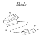
- FIG 1 illustrates a portable terminal 100, a charger 200 for charging the portable terminal 100 and a plug-socket 300 for supplying power in the related art.
- the charger 200 is constructed with a terminal fixed board 200A for fixing the portable terminal 100 during charging, an adapter 200B for applying DC power to the terminal fixed board 200A, and a wire 200C for connecting the terminal fixed board 200A to the adapter 200B.
- the terminal fixed board 200A is constructed with an upper casing 210 formed with a certain internal space, a lower casing 220 for supporting the upper casing 210, a PCB (printed circuit board) 230 installed within the internal space of the terminal fixed board 200A.
- a mounting groove 211 is formed on the upper portion of the upper casing 210 in order to mount the portable terminal 100 and a locking pin 212 projected from both internal sides of the mounting groove 211 of the portable terminal 100.
- the upper casing also has a fixed protrusion 213 projecting from both sides on the lower end of the terminal fixed board 200A so as to match with a fixation groove formed on the both sides of the portable terminal 100, a lamp 214 for indicating a charge state of the portable terminal 100, and a charge terminal 215 contacting a connector on the portable terminal 100.
- the portable terminal 100 is connected through an adapter 200B of the charger 200 to a plug socket 300 supplying power. Charging begins when the lower end of the portable terminal 100 is placed into the upper end (entrance) of the mounting groove 211 in the portable terminal 100.
- a fixed protrusion 213 formed at the terminal fixed board 200A is inserted into a fixed groove formed at the lower end of the portable terminal 100.
- a locking pin 212 of the terminal fixed board 200A is inserted into a locking groove formed at the sides of the portable terminal 100.
- the portable terminal 100 is mounted in the charger 200, where the charger 200 is connected via a wire 200C to the adaptor 200B. Additionally, the lamp 214 of the charger 200 often emits a red light indicating the charging of the portable terminal 100.
- the lamp 214 After a certain time has passed in that state, the lamp 214 often emits a green light indicating the end of the charging. At this point, the user separates the portable terminal 100 from the charger 200 by reversing the above-described mounting processes.
- the portable terminal 100 can not be charged while connected to a computer. As such, a data communication with the computer while the portable terminal 100 is charging can not be accomplished.
- An object of the invention is to solve at least the above problems and/or disadvantages and to provide at least the advantages described hereinafter.
- a charger for a portable terminal which is capable of making a portable terminal perform a data communication with a computer during charge by connecting a communication cable to the computer and the portable terminal through the charger.
- a charger for a portable terminal including a fixation unit for mounting a portable terminal and a connector insertion groove which allows connection of a communication cable to a portable terminal.
- a charger of a portable terminal including an upper casing connectable to a portable terminal, a communication cable of an information processing system connectable to a portable terminal and an information processing system, a lower casing supporting the upper casing, and a printed circuit board (PCB) including soldered electrical parts for charging a portable terminal.
- PCB printed circuit board
- a charger and data communicator for a portable terminal including a mounting unit capable of connection to a power source and a groove in the mounting unit capable of allowing a connector portion of a cable to be attached thereto, wherein a connector portion of a cable is attached to a portable terminal through the groove when a portable terminal is supported by the mounting unit.
- a method of charging and utilizing a mobile telephone with an information processing system including mounting a mobile telephone to a charging unit, directly connecting the mobile telephone to a data communication device while the mobile telephone is mounted to the charging unit, connecting an information processing system to a data communication device, and transferring data to a mobile telephone from an information processing system, wherein the transferring of the data and a charging of a mobile telephone occur concurrently while a mobile telephone is mounted to the charging unit.
- FIG 3 illustrates a charger for a portable terminal in accordance with a preferred embodiment of the present invention.
- a communication cable or any other connecting device must be connected between the data device and the portable terminal while the portable terminal is also connected to the charger 200.
- the charger 200 for a portable terminal in accordance with a preferred embodiment of the present invention includes a connector insertion groove 216 formed in the terminal fixed board 200A to allow for space for the connector.
- the connector insertion groove 216 can be formed at a lower portion of the upper casing 210 of the terminal fixed board 200A or any appropriate position that aligns with the portable terminal's communication receptacle 110.
- a connector 420 of a communication cable or other communicating device can be connected to both the computer 400 and the portable terminal 100.
- the connector insertion groove 216 can be placed at a reciprocal position to the position of a receiving receptacle 110 for the connector of the portable terminal 100.
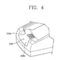
- FIG 4 is an enlarged view illustrating the charger 200 for the portable terminal 100 in accordance with a preferred embodiment of the present invention.
- the connector insertion groove 216 can be constructed with two walls 216a and a bottom surface 216b between the walls 216a.
- the walls 216a can be spaced apart from each other by a distance which allows for inserting the connector 420 into the receptacle 110 of the portable terminal 100, as also illustrated in Figure 6.
- the bottom surface 216b can be formed to slant so as to allow easier insertion of the connector 420 into the receptacle 110 of the portable terminal 100 if the portable terminal 100 is slanted-mounted onto the terminal fixed board 200A.
- the walls 216a can be spaced apart at a top section to provide a receptacle 110 region which is about the same width as the connector 420 for a tight fit of the connector 420.
- the walls can also have a bottom section wider than the top section to allow for easier insertion of the connector 420 into the receptacle 110.
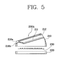
- FIG. 5 is a sectional view illustrating the charger 200 for the portable terminal 100 taken along the line A-A' of Figure 3.
- the terminal fixed board 200A of the charger 200 is constructed with the upper casing 210, the lower casing 220, the PCB 230, the mounting groove 211, the locking pin 212, the walls 216a and the bottom surface 216b of the connector insertion groove 216.
- Figure 6 illustrates the portable terminal 100 mounted onto the charger 200 and connected to a connector of a computer while being charged.
- Figure 6 illustrates a computer 400 with a communication cable 410 for connecting the computer 400 to the portable terminal 100 and a connector 420 for connecting to the portable terminal 100 through a receptacle 110 of the portable terminal 100 connected to the connector 420.
- Figure 6 includes the portable terminal 100, the charger 200 for charging the portable terminal 100, and a plug socket 300.
- the charger 200 illustrates the connector insertion groove large enough to accommodate the connection of the connector 420 to the receptacle 110, but the shape of the groove is better illustrated in Figures 3 and 4.
- the user of the portable terminal 100 can contact the adapter 200C of the charger 200 to the plug socket 300 by slide-mounting the portable terminal 100 onto the mounting groove 211 formed at the upper surface of the terminal fixed board 200A of the charger 200. After that, in order to connect the portable terminal 100 to the computer 400, the user can insert the connector 420 of the communication cable 410, which is connected to the computer 400, into the receptacle 110 of the portable terminal 100 through the connector insertion groove 216 formed at the terminal fixed board 200A.
- the portable terminal 100 When the connector 420 connected to the computer 400 is inserted into the receptacle 110 of the portable terminal 100, data transfer capability starts, and the user can start a data communication using the computer 400 while charging occurs with the connector 420 and charger 200 securely in place. As such, the portable terminal 100 can perform a data communication while being charged with a low likelihood for disturbance of either the data communication or the charging.
Landscapes
- Engineering & Computer Science (AREA)
- Theoretical Computer Science (AREA)
- Power Engineering (AREA)
- General Physics & Mathematics (AREA)
- Physics & Mathematics (AREA)
- General Engineering & Computer Science (AREA)
- Human Computer Interaction (AREA)
- Computer Hardware Design (AREA)
- Charge And Discharge Circuits For Batteries Or The Like (AREA)
- Telephone Set Structure (AREA)
- Telephone Function (AREA)
- Mobile Radio Communication Systems (AREA)
- Secondary Cells (AREA)
Applications Claiming Priority (2)
| Application Number | Priority Date | Filing Date | Title |
|---|---|---|---|
| KR1020010032064A KR20020093348A (ko) | 2001-06-08 | 2001-06-08 | 휴대용 단말기의 충전장치 |
| KR2001032064 | 2001-06-08 |
Publications (2)
| Publication Number | Publication Date |
|---|---|
| EP1265334A2 true EP1265334A2 (fr) | 2002-12-11 |
| EP1265334A3 EP1265334A3 (fr) | 2006-06-14 |
Family
ID=19710557
Family Applications (1)
| Application Number | Title | Priority Date | Filing Date |
|---|---|---|---|
| EP02012563A Withdrawn EP1265334A3 (fr) | 2001-06-08 | 2002-06-05 | Chargeur pour terminal portable |
Country Status (5)
| Country | Link |
|---|---|
| US (1) | US20020195991A1 (fr) |
| EP (1) | EP1265334A3 (fr) |
| JP (1) | JP2003069490A (fr) |
| KR (1) | KR20020093348A (fr) |
| CN (1) | CN1391417A (fr) |
Cited By (5)
| Publication number | Priority date | Publication date | Assignee | Title |
|---|---|---|---|---|
| GB2419472A (en) * | 2004-01-28 | 2006-04-26 | Milwaukee Electric Tool Corp | Electrical appliance with detachable battery charger |
| GB2410619B (en) * | 2004-01-28 | 2008-04-16 | Milwaukee Electric Tool Corp | Radio with a removably connectable battery charger |
| US7471063B2 (en) | 2001-11-09 | 2008-12-30 | Milwaukee Electric Tool Corporation | Electrical combination, electrical component and battery charger |
| US7557537B2 (en) | 2001-11-09 | 2009-07-07 | Milwaukee Electric Tool Corporation | Electrical component having a selectively connectable battery charger |
| US7741809B2 (en) | 2006-01-06 | 2010-06-22 | Milwaukee Electric Tool Corporation | Electrical component including a battery receptacle for including a battery |
Families Citing this family (6)
| Publication number | Priority date | Publication date | Assignee | Title |
|---|---|---|---|---|
| KR100677394B1 (ko) | 2004-11-16 | 2007-02-02 | 엘지전자 주식회사 | 냉각패드를 구비한 충전거치대 |
| KR100703408B1 (ko) * | 2004-12-06 | 2007-04-03 | 삼성전자주식회사 | 가로 거치 겸용 세로 거치 유형 충전 거치대 |
| EP3203008B1 (fr) * | 2006-03-27 | 2019-10-23 | VKR Holding A/S | Élément de support pour supporter un dispositif d'écran dans un cadre de fenêtre ou de porte |
| JP5094309B2 (ja) * | 2007-09-26 | 2012-12-12 | 三洋電機株式会社 | 通信装置及び充電器 |
| TWI550382B (zh) * | 2012-12-24 | 2016-09-21 | 鴻海精密工業股份有限公司 | 可擕式充電裝置 |
| DK3205808T3 (da) * | 2016-02-10 | 2021-03-15 | Vkr Holding As | Afskærmningsanordning med monteringsbeslag |
Family Cites Families (4)
| Publication number | Priority date | Publication date | Assignee | Title |
|---|---|---|---|---|
| US5479479A (en) * | 1991-10-19 | 1995-12-26 | Cell Port Labs, Inc. | Method and apparatus for transmission of and receiving signals having digital information using an air link |
| JPH11355407A (ja) * | 1998-06-08 | 1999-12-24 | Mitsubishi Electric Corp | 充電装置および充電装置用アタッチメント |
| JP2000315529A (ja) * | 1999-05-06 | 2000-11-14 | Matsushita Electric Ind Co Ltd | 充電器 |
| JP3420127B2 (ja) * | 1999-08-17 | 2003-06-23 | 埼玉日本電気株式会社 | 電池パックを用いた携帯電話機内蔵充電器給電システム及び方法 |
-
2001
- 2001-06-08 KR KR1020010032064A patent/KR20020093348A/ko not_active Withdrawn
-
2002
- 2002-05-23 CN CN02120616A patent/CN1391417A/zh active Pending
- 2002-05-29 JP JP2002156526A patent/JP2003069490A/ja active Pending
- 2002-05-30 US US10/156,789 patent/US20020195991A1/en not_active Abandoned
- 2002-06-05 EP EP02012563A patent/EP1265334A3/fr not_active Withdrawn
Cited By (6)
| Publication number | Priority date | Publication date | Assignee | Title |
|---|---|---|---|---|
| US7471063B2 (en) | 2001-11-09 | 2008-12-30 | Milwaukee Electric Tool Corporation | Electrical combination, electrical component and battery charger |
| US7557537B2 (en) | 2001-11-09 | 2009-07-07 | Milwaukee Electric Tool Corporation | Electrical component having a selectively connectable battery charger |
| US7609027B2 (en) | 2001-11-09 | 2009-10-27 | Milwaukee Electric Tool Corporation | Electrical component, audio component, or electrical combination having a selectively connectable battery charger |
| GB2419472A (en) * | 2004-01-28 | 2006-04-26 | Milwaukee Electric Tool Corp | Electrical appliance with detachable battery charger |
| GB2410619B (en) * | 2004-01-28 | 2008-04-16 | Milwaukee Electric Tool Corp | Radio with a removably connectable battery charger |
| US7741809B2 (en) | 2006-01-06 | 2010-06-22 | Milwaukee Electric Tool Corporation | Electrical component including a battery receptacle for including a battery |
Also Published As
| Publication number | Publication date |
|---|---|
| KR20020093348A (ko) | 2002-12-16 |
| EP1265334A3 (fr) | 2006-06-14 |
| JP2003069490A (ja) | 2003-03-07 |
| CN1391417A (zh) | 2003-01-15 |
| US20020195991A1 (en) | 2002-12-26 |
Similar Documents
| Publication | Publication Date | Title |
|---|---|---|
| EP0892468A2 (fr) | Assemblage de connecteur électrique avec moyen de polarisation | |
| KR960016775B1 (ko) | 일체형 행-업 및 배터리 충전 장치 | |
| US5020090A (en) | Apparatus for removably connecting a cellular portable telephone to a computer | |
| US9134761B2 (en) | Attachable charger | |
| EP1265334A2 (fr) | Chargeur pour terminal portable | |
| JP2001512893A (ja) | 表面に取り付け可能な電気的コネクタ装置 | |
| FI109562B (fi) | Sähköliittimien asennusjärjestelmä | |
| KR100387910B1 (ko) | 부동 가이드 커넥터 및 방법 | |
| US5947752A (en) | Video data transmission connector and transmission cable mounting arrangement | |
| US6231390B1 (en) | Connector for use in portable phone | |
| JP2003234925A (ja) | 監視カメラ装置 | |
| CN110098544A (zh) | 一种可调插头的手机充电器 | |
| US6354870B1 (en) | Apparatus and method for mounting small electrical connector | |
| US7581992B1 (en) | Power adapter | |
| US11398737B2 (en) | Charging station for telecommunication or small electronic devices | |
| US6102714A (en) | Electrical connectors having dual biased contact pins | |
| US6960099B2 (en) | Low profile interface connector | |
| US20030013332A1 (en) | Structure of plug-in power supply apparatus | |
| US6120307A (en) | Modular connector with printed circuit board | |
| CN212304807U (zh) | 移动电源及电子设备 | |
| KR100629533B1 (ko) | 영상표시기기의 거치 및 충전구조 | |
| WO2004105197A1 (fr) | Ensemble de connexion electrique comprenant des moyens de verrouillage ameliores | |
| US5755590A (en) | Line cord strain relief attachment for telephone test set | |
| US20060138998A1 (en) | Battery charger | |
| CN213705191U (zh) | 连接装置、无人机的无线充电发射装置与系统 |
Legal Events
| Date | Code | Title | Description |
|---|---|---|---|
| PUAI | Public reference made under article 153(3) epc to a published international application that has entered the european phase |
Free format text: ORIGINAL CODE: 0009012 |
|
| AK | Designated contracting states |
Kind code of ref document: A2 Designated state(s): AT BE CH CY DE DK ES FI FR GB GR IE IT LI LU MC NL PT SE TR |
|
| AX | Request for extension of the european patent |
Free format text: AL;LT;LV;MK;RO;SI |
|
| PUAL | Search report despatched |
Free format text: ORIGINAL CODE: 0009013 |
|
| AK | Designated contracting states |
Kind code of ref document: A3 Designated state(s): AT BE CH CY DE DK ES FI FR GB GR IE IT LI LU MC NL PT SE TR |
|
| AX | Request for extension of the european patent |
Extension state: AL LT LV MK RO SI |
|
| RIC1 | Information provided on ipc code assigned before grant |
Ipc: G06F 1/16 20060101ALI20060511BHEP Ipc: H02J 7/00 20060101AFI20021002BHEP |
|
| AKX | Designation fees paid | ||
| STAA | Information on the status of an ep patent application or granted ep patent |
Free format text: STATUS: THE APPLICATION IS DEEMED TO BE WITHDRAWN |
|
| 18D | Application deemed to be withdrawn |
Effective date: 20061215 |
|
| REG | Reference to a national code |
Ref country code: DE Ref legal event code: 8566 |