EP1265459A2 - Alimentation électrique de commande de magnétron - Google Patents
Alimentation électrique de commande de magnétron Download PDFInfo
- Publication number
- EP1265459A2 EP1265459A2 EP02012327A EP02012327A EP1265459A2 EP 1265459 A2 EP1265459 A2 EP 1265459A2 EP 02012327 A EP02012327 A EP 02012327A EP 02012327 A EP02012327 A EP 02012327A EP 1265459 A2 EP1265459 A2 EP 1265459A2
- Authority
- EP
- European Patent Office
- Prior art keywords
- power supply
- voltage
- zero
- frequency
- frequency inverter
- Prior art date
- Legal status (The legal status is an assumption and is not a legal conclusion. Google has not performed a legal analysis and makes no representation as to the accuracy of the status listed.)
- Granted
Links
Images


Classifications
-
- H—ELECTRICITY
- H05—ELECTRIC TECHNIQUES NOT OTHERWISE PROVIDED FOR
- H05B—ELECTRIC HEATING; ELECTRIC LIGHT SOURCES NOT OTHERWISE PROVIDED FOR; CIRCUIT ARRANGEMENTS FOR ELECTRIC LIGHT SOURCES, IN GENERAL
- H05B6/00—Heating by electric, magnetic or electromagnetic fields
- H05B6/64—Heating using microwaves
- H05B6/66—Circuits
- H05B6/68—Circuits for monitoring or control
-
- H—ELECTRICITY
- H05—ELECTRIC TECHNIQUES NOT OTHERWISE PROVIDED FOR
- H05B—ELECTRIC HEATING; ELECTRIC LIGHT SOURCES NOT OTHERWISE PROVIDED FOR; CIRCUIT ARRANGEMENTS FOR ELECTRIC LIGHT SOURCES, IN GENERAL
- H05B6/00—Heating by electric, magnetic or electromagnetic fields
- H05B6/64—Heating using microwaves
- H05B6/66—Circuits
- H05B6/666—Safety circuits
Definitions
- This invention relates to a magnetron drive power supply with a magnetron of a microwave oven, etc., as a load.
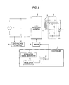
- FIG. 8 is a circuit block diagram of a magnetron drive power supply in a related art.
- a semiconductor switch in a high-frequency inverter 2 is controlled by controller 7, whereby a commercial power supply 1 is converted into radio-frequency power of 20 to 50 kHz and the radio-frequency power is supplied to a high-voltage transformer 3.
- a high-voltage rectification circuit 4 and a magnetron 5 are connected to the secondary side of the high-voltage transformer 3 and a DC high voltage is applied to the magnetron 5 for generating a 2.45-GHz radio wave.
- Zero-voltage detector 6 detects a zero voltage point of the power supply voltage 1 and causes modulation signal generator 9 to generate a modulation wave form responsive to the power supply phase.
- the modulation signal generator 9 Upon reception of input of zero voltage detection from the zero-voltage detector 6, the modulation signal generator 9 outputs a modulation waveform of one period of the power supply voltage 1 as a peak value responsive to the setup value of input current.
- the controller 7 can control the input current to the form close to a sine wave.
- the controller 7 performs 20 to 50-kHz PWM modulation of the modulation signal by oscillator 10 and transmits the signal to driver 8, thereby controlling the on-duration of the semiconductor switch in the high-frequency inverter 2.
- voltage detection with a transformer using a photocoupler, etc. is available.
- the controller 7, control of a microcomputer, etc. is used.
- FIGS. 9A to 9D are waveform charts of the magnetron drive power supply in the related art.
- a signal of commercial power supply Fig. 9A
- a signal of zero voltage detection Fig. 9B
- the rising edge of the signal of the zero-voltage detector 6 is detected and a modulation signal (Fig. 9C) preset so that the input current becomes a predetermined value and moreover the power factor of the input current becomes close to 1 is output for one period of the commercial power supply 1.
- the modulation signal (Fig. 9C) is compared with the oscillation frequency of oscillator output (Fig.
- the controller 7 performs such control, whereby electric power having a current waveform with a less harmonic component with a good power factor can be supplied.
- the modulation waveform deviates from the essential timing and a possibility of leading to a failure of the high-frequency inverter because of overvoltage, overcurrent, etc., occurs.
- a magnetron drive power supply comprising: a commercial power supply; a high-frequency inverter which converts electric power of the commercial power supply into high-frequency power and supplies the high-frequency power to a high-voltage transformer; a high-voltage rectification circuit and a magnetron being connected to secondary output of the high-voltage transformer; zero-voltage detector which detects zero voltage of the commercial power supply; and controller which controls the high-frequency inverter in response to output of the zero-voltage detector, wherein the controller predicts the detection timing of zero voltage by the zero-voltage detector in each period and enables the output from the zero-voltage detector to be received only for a given time before and after the predicted detection timing.
- the zero-voltage detector or the power supply voltage carries noise, the voltage zero point is not largely mistaken, so that overcurrent, overvoltage, etc., does not occur and the magnetron drive power supply that can stably operate can be realized.
- the given time before and after the predicted detection timing contains a period in which the output from the zero-voltage detector is not received, it is assumed that the output from the zero-voltage detector is received, and controlling the high-frequency inverter is continued.
- the controller stops the high-frequency inverter if a period in which the output from the zero-voltage detector is not received occurs successively a stipulated number of times in the given time before and after the predicted detection timing.
- a magnetron drive power supply comprising: a commercial power supply; a high-frequency inverter which converts electric power of the commercial power supply into high-frequency power and supplies the high-frequency power to a high-voltage transformer; a high-voltage rectification circuit and a magnetron being connected to secondary output of the high-voltage transformer; input current detector which detects the current value of the high-frequency inverter; and controller which controls the high-frequency inverter, wherein if the detection value of the input current detector has a predetermined difference from a target value continuously for a given time, the controller stops the high-frequency inverter.
- the predetermined difference between the detection value of the input current detector and the target value is set in response to the target value.
- the reference numerals defines as follow, 1, Commercial power supply; 2, High-frequency inverter; 3, High-voltage transformer; 4, High-voltage rectification circuit; 5, Magnetron; 6, Zero-voltage detector; 7, Controller; 8, Driver; 9, Modulation signal generator; 10, Oscillator; 11, Comparator; 12, Zero-voltage detection permission means; 13, Input current detector; 14, Command value signal; 15, Error determination means; and 16, Modulation signal MAX definition means.
- FIG. 1 shows the circuit configuration of a magnetron drive power supply of the first embodiment of the invention. Partsidentical with those previously described with reference to FIG. 8 are denoted by the same reference numerals in FIG. 1 and will not be discussed again in detail.
- a commercial power supply 1 transmits high-frequency power through a high-frequency inverter 2 to a high-voltage transformer 3.
- a high-voltage rectification circuit 4 is connected to secondary winding output of the high-voltage transformer 3 for applying a DC high voltage to a magnetron 5.
- the magnetron 5 generates a 2.45-GHz radio wave based on the DC high voltage.
- Zero-voltage detector 6 which detects the timing of zero voltage of the commercial power supply is connected to an output section of the commercial power supply 1 and further controller 7 which controls the on-time of a semiconductor switch in the high-frequency inverter 2 in accordance with a signal of the zero-voltage detector 6 and a current command value is connected to output of the zero-voltage detector 6.
- driver 8 which actually giving a drive signal to the semiconductor switch in the high-frequency inverter 2 upon reception of a signal from the controller 7 is connected to the controller 7.
- the controller 7 is made up of modulation signal generator 9 which determines a modulation signal of the on-time of the semiconductor switch in the high-frequency inverter 2 in accordance with the signal of the zero-voltage detector 6, zero-voltage detection permission means 12 for permitting reception of the signal of the zero-voltage detector 6, oscillator 10 which outputs an oscillation waveform for determining the operation frequency of the semiconductor switch, comparator 11 which compares between signals from the modulation signal generator 9 and the oscillator 10 and generates a drive signal supplied to the semiconductor switch, and the like.
- Electric power supplied from the commercial power supply 1 is supplied through the semiconductor switch in the high-frequency inverter 2 to the high-voltage transformer 3 as high-frequency power of 20 to 50 kHz.
- the high-frequency power is rectified by the high-voltage rectification circuit 4 connected to the secondary side of the high-voltage transformer 3 for supplying a high DC voltage to a magnetron 5.
- the magnetron 5 oscillates at 2.45 GHz based on the DC voltage.
- the controller 7 receives the zero phase timing from the zero-voltage detector 6 detecting the timing of zero voltage of the commercial power supply 1 and outputs a modulation waveform preset so that the target current value, the input current, and the power factor become good for one period of the power supply by the modulation signal generator 9.
- the controller 7 receives the zero phase timing from the zero-voltage detector 6 detecting the timing of zero voltage of the commercial power supply 1 and outputs a modulation waveform preset so that the target current value, the input current, and the power factor become good for one period of the power supply by the modulation signal generator 9.
- the timing at which zero voltage occurs is almost preknown from the period of the commercial power supply 1 and thus signal is accepted only for 1 to 2 msec before and after it is predicted that zero voltage will come by the zero-voltage detection permissionmeans 12. Accordingly, it is made possible to prevent erroneous detection of the zero-voltage timing because of restoration from instantaneous power interruption, noise, etc.
- the comparator 11 compares the modulation signal output from the modulation signal generator 9 with the oscillation waveform at a frequency of 20 to 50 kHz output from the oscillator 10 and supplies a drive signal to the driver 8 as a PWM signal.
- the zero-voltage detector 6 a method of using a transformer, a method of using a photocoupler, etc., is possible, but the zero-voltage detector 6 is not limited.
- FIGS. 2A to 2D are waveform charts of the magnetron drive power supply of the embodiment.
- a signal of commercial power supply Fig. 2A
- a signal of zero voltage detection Fig. 2B
- the rising edge of the signal of the zero-voltage detector 6 is detected and a modulation signal (d) preset so that the input current becomes a predetermined value and moreover the power factor of the input current becomes close to 1 is output for one period of the commercial power supply 1.
- the modulation signal (Fig. 2D) is compared with the oscillation frequency of oscillator output by comparator 11, whereby the signal is subjected to PWM modulation and is supplied to the driver 8 as a drive signal.
- the zero-voltage detector 6 or the power supply voltage 1 carries noise, the voltage zero point is not largely mistaken, so that overcurrent, overvoltage, etc., does not occur and the magnetron drive power supply that can stably operate can be realized.
- FIGS. 3A to 3D show operation waveforms of a magnetron drive power supply of the second embodiment of the invention.
- the circuit configuration of the embodiment is similar to that previously described with reference to FIG. 1 and detailed description of reference numerals, etc., is not given.
- controller 7 predicts the timing at which the zero-voltage detection signal comes, and outputs a modulation signal (Fig. 3D) by assuming that the zero-voltage signal comes at the timing. Accordingly, it is made possible to continue the operation with safety if short instantaneous power interruption of about several msec occurs.
- FIGS. 4A to 4E show operation waveforms of a magnetron drive power supply of the third embodiment of the invention.
- the circuit configuration of the embodiment is similar to that previously described with reference to FIG. 1 and detailed description of reference numerals, etc., is not given..
- controller 7 determines that instantaneous power interruption occurs, and stops a high-frequency inverter 2. Accordingly, it is made possible to stop the inverter with safety when comparatively long instantaneous power interruption occurs.
- the system of determining the on-time waveform for power supply period with the zero voltage, etc., as the reference as in the system is excellent in stability and the operation continues with safety if comparatively long instantaneous power interruption occurs, but there is a possibility that power supply, etc., of the controller 7 will become unstable, and thus the inverter is stopped.
- the embodiment it is made possible to stop the inverter with safety if comparatively long-time instantaneous power interruption of the commercial power supply occurs, and the magnetron drive power supply that can operate without a failure caused by a power outage can be realized.
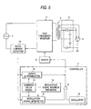
- FIG. 5 shows the circuit configuration of a magnetron drive power supply of the fourth embodiment of the invention. Parts identical with those previously described with reference to FIG. 8 are denoted by the same reference numerals in FIG. 1 and will not be discussed again in detail.
- a commercial power supply 1 transmits high-frequency power through a high-frequency inverter 2 to a high-voltage transformer 3.
- a high-voltage rectification circuit 4 is connected to secondary winding output of the high-voltage transformer 3 for applying a DC high voltage to a magnetron 5.
- the magnetron 5 generates a 2.45-GHz radio wave based on the DC high voltage.
- Input current detector 13 for detecting an input current is connected to an output section of the commercial power supply 1 and further controller 7 for controlling the on time of a semiconductor switch in the high-frequency inverter 2 in accordance with a command value signal 14 determining the command current value of the input current is connected to output of the input current detector 13.
- driver 8 for actually giving a drive signal to the semiconductor switch in the high-frequency inverter 2 upon reception of a signal from the controller 7 is connected to the controller 7.
- the controller 7 is made up of modulation signal generator 9 for determining a modulation signal of the on time of the semiconductor switch in the high-frequency inverter 2 in accordance with the command value signal 14, modulation signal MAX definition means 16 for determining the upper limit value of the modulation signal generator 9, oscillator 10 for outputting an oscillation waveform for determining the operation frequency of the semiconductor switch, comparator 11 for making a comparison between signals from the modulation signal generator 9 and the oscillator 10 and generating a drive signal supplied to the semiconductor switch, error determination means 15 which determines the error between the command value signal 14 and the detection value of the input current detector 13, and the like.
- Electric power supplied from the commercial power supply 1 is supplied through the semiconductor switch in the high-frequency inverter 2 to the high-voltage transformer 3 as high-frequency power of 20 to 50 kHz.
- the high-frequency power is rectified by the high-voltage rectification circuit 4 connected to the secondary side of the high-voltage transformer 3 for supplying a high DC voltage to a magnetron 5.
- the magnetron 5 oscillates at 2.45 GHz based on the DC voltage.
- the controller 7 generates a modulation signal by the modulation signal generator 9 so that the command current value set by the command value signal 14 is reached.
- the comparator 11 compares the modulation signal output from the modulation signal generator 9 with the oscillation waveform at a frequency of 20 to 50 kHz output from the oscillator 10 and supplies a drive signal to the driver 8 as a PWM signal. If the voltage of the commercial power supply 1 lowers, when an attempt is made to ensure the current value of the command value, it is necessary to set long the on time of the semiconductor switch in the high-frequency inverter 2 and it becomes difficult to ensure the voltage resistance of the semiconductor switch.
- the upper limit of the on time is defined by the modulation signal MAX definition means 16, whereby if the voltage of the commercial power supply 1 lowers, the input current can be suppressed and it is made possible to prevent exceeding the voltage resistance of the semiconductor switch, etc. If an error of a given value or more remains between the input current and the command value, it is seen that the voltage of the commercial power supply 1 lowers. Seeing the error, it is made possible to recognize that the power supply voltage lowers without detecting the voltage of the commercial power supply 1.
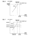
- FIG. 6 shows the relationship of the error between the input current value and the command value (target value) when the voltage of the commercial power supply 1 lowers. From the figure, it is seen that if the current value decreases as the power supply voltage lowers and an error of a given value or more continues, it is assumed that the voltage of the commercial power supply 1 decreases.
- the magnetron drive power supply having the voltage lowering protection function can be realized at low cost.
- FIG. 7 shows the characteristic of a magnetron drive power supply of the fifth embodiment of the invention.
- the circuit configuration of the embodiment is similar to that of the fourth embodiment previously described with reference to FIG. 5 and detailed description of reference numerals, etc., is not given.
- the tolerance (predetermined difference) of an error from the current value detected by current detector 13 according to the command value of a command value signal 14 is changed for each command value (target value).
- a modulation signal reaches the maximum value early and thus the error of the current value exceeds predetermined tolerance where the voltage is comparatively high.
- the modulation signal reaches the maximum value late and thus the error is hard to exceed the tolerance and unless the commercial power supply 1 lowers considerably, the commercial power supply 1 lowering cannot be detected.
- the tolerance is changed for each command value, whereby the voltage lowering detection level of the commercial power supply 1 can be made almost constant.
- several levels may be provided for each command value or replacement with a function involves no problem; as the command current value increases, the tolerance needs to be set larger.
- the embodiment it is made possible to detect the input voltage of the commercial power supply 1 lowering almost at constant voltage independently of the input current, and the magnetron drive power supply having the voltage lowering protection function can be realized at low cost.
- the zero-voltage detect or or the power supply voltage carries noise, the voltage zero point is not largely mistaken, so that overcurrent, overvoltage, etc., does not occur and the magnetron drive power supply that can stably operate can be realized.
Landscapes
- Physics & Mathematics (AREA)
- Electromagnetism (AREA)
- Control Of High-Frequency Heating Circuits (AREA)
- Power Conversion In General (AREA)
Priority Applications (1)
| Application Number | Priority Date | Filing Date | Title |
|---|---|---|---|
| EP06012975A EP1705958A1 (fr) | 2001-06-04 | 2002-06-04 | Alimentation électrique de commande de magnétron |
Applications Claiming Priority (2)
| Application Number | Priority Date | Filing Date | Title |
|---|---|---|---|
| JP2001167985 | 2001-06-04 | ||
| JP2001167985A JP2002367768A (ja) | 2001-06-04 | 2001-06-04 | マグネトロン駆動用電源 |
Related Child Applications (1)
| Application Number | Title | Priority Date | Filing Date |
|---|---|---|---|
| EP06012975A Division EP1705958A1 (fr) | 2001-06-04 | 2002-06-04 | Alimentation électrique de commande de magnétron |
Publications (3)
| Publication Number | Publication Date |
|---|---|
| EP1265459A2 true EP1265459A2 (fr) | 2002-12-11 |
| EP1265459A3 EP1265459A3 (fr) | 2005-08-10 |
| EP1265459B1 EP1265459B1 (fr) | 2007-09-12 |
Family
ID=19010283
Family Applications (2)
| Application Number | Title | Priority Date | Filing Date |
|---|---|---|---|
| EP06012975A Withdrawn EP1705958A1 (fr) | 2001-06-04 | 2002-06-04 | Alimentation électrique de commande de magnétron |
| EP02012327A Expired - Lifetime EP1265459B1 (fr) | 2001-06-04 | 2002-06-04 | Alimentation électrique de commande de magnétron |
Family Applications Before (1)
| Application Number | Title | Priority Date | Filing Date |
|---|---|---|---|
| EP06012975A Withdrawn EP1705958A1 (fr) | 2001-06-04 | 2002-06-04 | Alimentation électrique de commande de magnétron |
Country Status (6)
| Country | Link |
|---|---|
| US (2) | US6624401B2 (fr) |
| EP (2) | EP1705958A1 (fr) |
| JP (1) | JP2002367768A (fr) |
| KR (1) | KR100859444B1 (fr) |
| CN (2) | CN1250048C (fr) |
| DE (1) | DE60222325T2 (fr) |
Cited By (2)
| Publication number | Priority date | Publication date | Assignee | Title |
|---|---|---|---|---|
| WO2005109957A1 (fr) | 2004-05-10 | 2005-11-17 | Matsushita Electric Industrial Co., Ltd. | Appareil de chauffage à haute-fréquence |
| EP1742512A4 (fr) * | 2004-04-28 | 2014-08-13 | Panasonic Corp | Appareil de chauffage haute frequence |
Families Citing this family (20)
| Publication number | Priority date | Publication date | Assignee | Title |
|---|---|---|---|---|
| KR100453242B1 (ko) * | 2002-10-10 | 2004-10-15 | 삼성전자주식회사 | 전자렌지 및 그 제어방법 |
| JP4301867B2 (ja) * | 2003-05-30 | 2009-07-22 | 田淵電機株式会社 | 高周波加熱装置のインバータ電源制御回路 |
| KR100656804B1 (ko) * | 2005-01-31 | 2006-12-13 | 주식회사 동성실리콘 | 실리콘을 포함하는 기능성 카페트 |
| CN1838849B (zh) * | 2005-03-23 | 2011-05-11 | 新巨企业股份有限公司 | 应用于变动电压的反流器控制方法 |
| GB0526626D0 (en) * | 2005-12-30 | 2006-02-08 | Microgen Energy Ltd | A method of regulating an AC signal |
| US7224589B2 (en) * | 2005-08-12 | 2007-05-29 | Zippy Technology Corp. | Inverter circuit for producing power factor correction effect |
| GB0526635D0 (en) * | 2005-12-30 | 2006-02-08 | Microgen Energy Ltd | Switching controller |
| GB0526625D0 (en) * | 2005-12-30 | 2006-02-08 | Microgen Energy Ltd | Power supply |
| US8193797B2 (en) * | 2008-04-16 | 2012-06-05 | Nxp B.V. | Self-oscillating switched mode converter with valley detection |
| JP2011060566A (ja) * | 2009-09-10 | 2011-03-24 | Panasonic Corp | 高周波加熱装置 |
| IT1398695B1 (it) * | 2010-03-09 | 2013-03-08 | Tci Telecomunicazioni Italia Srl | Rivelatore presenza rete ac per lampade a led provviste di modalita' emergenza |
| WO2013175620A1 (fr) * | 2012-05-25 | 2013-11-28 | 三菱電機株式会社 | Dispositif de conversion de puissance |
| JP5945723B2 (ja) * | 2012-07-24 | 2016-07-05 | パナソニックIpマネジメント株式会社 | 炊飯器 |
| CN104868764B (zh) * | 2014-02-26 | 2017-08-04 | 全汉企业股份有限公司 | 逆变装置及其电源转换方法 |
| CN104613516B (zh) * | 2014-12-17 | 2016-11-09 | 美的集团股份有限公司 | 调节逆变器功率的控制系统及控制方法及微波炉 |
| CN105188178B (zh) * | 2015-10-10 | 2017-11-03 | 沈阳东软医疗系统有限公司 | 一种磁控管退灯丝电压的控制系统及方法 |
| CN108449821B (zh) * | 2018-02-23 | 2021-03-02 | 广东美的厨房电器制造有限公司 | 用于调节微波设备电磁兼容性的装置和方法以及微波设备 |
| CN110579720B (zh) | 2018-06-08 | 2022-08-30 | 台达电子工业股份有限公司 | 电源监控器 |
| CN110505726B (zh) * | 2019-08-07 | 2022-09-06 | 广东美的厨房电器制造有限公司 | 磁控管驱动电源及其控制方法和微波烹饪设备 |
| JP7700505B2 (ja) * | 2021-05-12 | 2025-07-01 | オムロン株式会社 | 複合共振回路の駆動制御装置及び非接触給電システム |
Family Cites Families (17)
| Publication number | Priority date | Publication date | Assignee | Title |
|---|---|---|---|---|
| KR890007224Y1 (ko) * | 1987-04-01 | 1989-10-20 | 주식회사 금성사 | 전자레인지의 순간 정전 보상회로 |
| AU592262B2 (en) * | 1987-04-30 | 1990-01-04 | Matsushita Electric Industrial Co., Ltd. | Magnetron feeding apparatus and method of controlling the same |
| KR910006174B1 (ko) * | 1987-07-27 | 1991-08-16 | 마쯔시다덴기산교 가부시기가이샤 | 고주파가열장치 |
| JPH07111918B2 (ja) * | 1987-07-28 | 1995-11-29 | 三菱電機株式会社 | マイクロ波放電光源装置 |
| US4900884A (en) * | 1987-11-28 | 1990-02-13 | Kabushiki Kaisha Toshiba | Composite cooking system having microwave heating and induction heating |
| JP2603984B2 (ja) * | 1988-02-16 | 1997-04-23 | 株式会社東芝 | 調理器 |
| JPH01302688A (ja) * | 1988-05-30 | 1989-12-06 | Toshiba Corp | 調理器 |
| JP3191053B2 (ja) * | 1990-11-27 | 2001-07-23 | 株式会社日立製作所 | 回生インバータの制御方法 |
| US5222015A (en) * | 1991-05-31 | 1993-06-22 | Kabushiki Kaisha Toshiba | Inverter power supply with input power detection means |
| KR930004375Y1 (ko) * | 1991-08-21 | 1993-07-12 | 주식회사 금성사 | 마이크로 웨이브 오븐의 인버터 보호회로 |
| KR930010608B1 (ko) * | 1991-09-18 | 1993-10-30 | 주식회사 금성사 | 인버터 전자 레인지의 순간 정전 보호회로 |
| KR100307732B1 (ko) * | 1994-06-02 | 2001-12-15 | 구자홍 | 고주파가열장치의제어회로 |
| KR0138209B1 (ko) * | 1994-11-17 | 1998-06-15 | 문정환 | 고주파 가열장치 |
| JP2001357970A (ja) * | 2000-06-16 | 2001-12-26 | Sharp Corp | 高周波加熱装置 |
| KR100399135B1 (ko) * | 2000-07-27 | 2003-09-26 | 삼성전자주식회사 | 전자렌지 및 그 제어방법 |
| KR20020044500A (ko) * | 2000-12-06 | 2002-06-15 | 윤종용 | 전자렌지 및 그 제어방법 |
| KR100586510B1 (ko) * | 2000-12-06 | 2006-06-07 | 삼성전자주식회사 | 전자렌지 및 그 제어방법 |
-
2001
- 2001-06-04 JP JP2001167985A patent/JP2002367768A/ja active Pending
-
2002
- 2002-06-03 US US10/161,368 patent/US6624401B2/en not_active Expired - Lifetime
- 2002-06-04 CN CNB021263884A patent/CN1250048C/zh not_active Expired - Fee Related
- 2002-06-04 KR KR1020020031281A patent/KR100859444B1/ko not_active Expired - Fee Related
- 2002-06-04 CN CNA2004100587356A patent/CN1592505A/zh active Pending
- 2002-06-04 EP EP06012975A patent/EP1705958A1/fr not_active Withdrawn
- 2002-06-04 DE DE60222325T patent/DE60222325T2/de not_active Expired - Lifetime
- 2002-06-04 EP EP02012327A patent/EP1265459B1/fr not_active Expired - Lifetime
-
2003
- 2003-07-23 US US10/625,266 patent/US7060954B2/en not_active Expired - Lifetime
Cited By (3)
| Publication number | Priority date | Publication date | Assignee | Title |
|---|---|---|---|---|
| EP1742512A4 (fr) * | 2004-04-28 | 2014-08-13 | Panasonic Corp | Appareil de chauffage haute frequence |
| WO2005109957A1 (fr) | 2004-05-10 | 2005-11-17 | Matsushita Electric Industrial Co., Ltd. | Appareil de chauffage à haute-fréquence |
| EP1737273A4 (fr) * | 2004-05-10 | 2009-06-03 | Panasonic Corp | Appareil de chauffage à haute-fréquence |
Also Published As
| Publication number | Publication date |
|---|---|
| KR100859444B1 (ko) | 2008-09-23 |
| EP1705958A1 (fr) | 2006-09-27 |
| DE60222325D1 (de) | 2007-10-25 |
| CN1395448A (zh) | 2003-02-05 |
| CN1250048C (zh) | 2006-04-05 |
| KR20020092826A (ko) | 2002-12-12 |
| JP2002367768A (ja) | 2002-12-20 |
| EP1265459A3 (fr) | 2005-08-10 |
| US20050189348A1 (en) | 2005-09-01 |
| US6624401B2 (en) | 2003-09-23 |
| EP1265459B1 (fr) | 2007-09-12 |
| US7060954B2 (en) | 2006-06-13 |
| US20020179597A1 (en) | 2002-12-05 |
| CN1592505A (zh) | 2005-03-09 |
| DE60222325T2 (de) | 2007-12-27 |
Similar Documents
| Publication | Publication Date | Title |
|---|---|---|
| US6624401B2 (en) | Magnetron drive power supply | |
| US5321235A (en) | Half-bridge converter switching power supply for magnetron | |
| US4727469A (en) | Control for a series resonant power converter | |
| EP1835608B1 (fr) | Procédé et dispositif pour fournir une source de puissance de courant continu | |
| US6091049A (en) | Power supply apparatus for use with arc utilizing device | |
| EP4420229B1 (fr) | Convertisseur de puissance c.c.-c.c. à résonance en série basé sur une commande multimode et méthode de commande | |
| US11936203B2 (en) | Method for operating a device for wireless transfer of energy in the direction of an electrical consumer by means of inductive coupling and device | |
| KR20020010195A (ko) | 전자렌지 및 그 제어방법 | |
| US7190596B2 (en) | Resonant converter with phase controlled switching | |
| EP1739819A1 (fr) | Appareil d'alimentation électrique | |
| US7768215B1 (en) | Method and system for controlling transient current signals in an electronic ballast | |
| JP2003109743A (ja) | マグネトロン駆動用電源 | |
| KR0164233B1 (ko) | 전자레인지 | |
| JP3446554B2 (ja) | 高周波加熱装置 | |
| JP3092482B2 (ja) | 高周波加熱装置 | |
| TWI839659B (zh) | 電力轉換裝置、電力轉換裝置的控制裝置以及控制方法 | |
| JP2653202B2 (ja) | 高周波加熱装置 | |
| JPH05251174A (ja) | 高周波加熱装置 | |
| JP3206512B2 (ja) | 高周波加熱装置 | |
| JP2000333447A (ja) | 圧電トランスコンバータの過電流保護方式 | |
| JP2021114807A (ja) | アーク加工電源装置 | |
| JPH11187646A (ja) | 交流電流制御装置及びその制御方法 | |
| JPH0935867A (ja) | 複合加熱調理器 | |
| JPH04111191U (ja) | 高周波加熱装置 | |
| JPH04111192U (ja) | 高周波加熱装置 |
Legal Events
| Date | Code | Title | Description |
|---|---|---|---|
| PUAI | Public reference made under article 153(3) epc to a published international application that has entered the european phase |
Free format text: ORIGINAL CODE: 0009012 |
|
| AK | Designated contracting states |
Kind code of ref document: A2 Designated state(s): AT BE CH CY DE DK ES FI FR GB GR IE IT LI LU MC NL PT SE TR |
|
| AX | Request for extension of the european patent |
Free format text: AL;LT;LV;MK;RO;SI |
|
| PUAL | Search report despatched |
Free format text: ORIGINAL CODE: 0009013 |
|
| AK | Designated contracting states |
Kind code of ref document: A3 Designated state(s): AT BE CH CY DE DK ES FI FR GB GR IE IT LI LU MC NL PT SE TR |
|
| AX | Request for extension of the european patent |
Extension state: AL LT LV MK RO SI |
|
| 17P | Request for examination filed |
Effective date: 20051021 |
|
| AKX | Designation fees paid |
Designated state(s): DE FR GB |
|
| GRAP | Despatch of communication of intention to grant a patent |
Free format text: ORIGINAL CODE: EPIDOSNIGR1 |
|
| GRAS | Grant fee paid |
Free format text: ORIGINAL CODE: EPIDOSNIGR3 |
|
| GRAA | (expected) grant |
Free format text: ORIGINAL CODE: 0009210 |
|
| AK | Designated contracting states |
Kind code of ref document: B1 Designated state(s): DE FR GB |
|
| REG | Reference to a national code |
Ref country code: GB Ref legal event code: FG4D |
|
| REF | Corresponds to: |
Ref document number: 60222325 Country of ref document: DE Date of ref document: 20071025 Kind code of ref document: P |
|
| ET | Fr: translation filed | ||
| PLBE | No opposition filed within time limit |
Free format text: ORIGINAL CODE: 0009261 |
|
| STAA | Information on the status of an ep patent application or granted ep patent |
Free format text: STATUS: NO OPPOSITION FILED WITHIN TIME LIMIT |
|
| 26N | No opposition filed |
Effective date: 20080613 |
|
| REG | Reference to a national code |
Ref country code: FR Ref legal event code: PLFP Year of fee payment: 15 |
|
| REG | Reference to a national code |
Ref country code: FR Ref legal event code: PLFP Year of fee payment: 16 |
|
| REG | Reference to a national code |
Ref country code: FR Ref legal event code: PLFP Year of fee payment: 17 |
|
| PGFP | Annual fee paid to national office [announced via postgrant information from national office to epo] |
Ref country code: FR Payment date: 20180327 Year of fee payment: 17 |
|
| PGFP | Annual fee paid to national office [announced via postgrant information from national office to epo] |
Ref country code: DE Payment date: 20180320 Year of fee payment: 17 |
|
| PGFP | Annual fee paid to national office [announced via postgrant information from national office to epo] |
Ref country code: GB Payment date: 20180530 Year of fee payment: 17 |
|
| REG | Reference to a national code |
Ref country code: DE Ref legal event code: R119 Ref document number: 60222325 Country of ref document: DE |
|
| GBPC | Gb: european patent ceased through non-payment of renewal fee |
Effective date: 20190604 |
|
| PG25 | Lapsed in a contracting state [announced via postgrant information from national office to epo] |
Ref country code: DE Free format text: LAPSE BECAUSE OF NON-PAYMENT OF DUE FEES Effective date: 20200101 Ref country code: GB Free format text: LAPSE BECAUSE OF NON-PAYMENT OF DUE FEES Effective date: 20190604 |
|
| PG25 | Lapsed in a contracting state [announced via postgrant information from national office to epo] |
Ref country code: FR Free format text: LAPSE BECAUSE OF NON-PAYMENT OF DUE FEES Effective date: 20190630 |