EP1266746A2 - Verfahren zur Herstellung von Pulverpresslingen und folienartigen Formteilen zur Verwendung in dem Verfahren - Google Patents
Verfahren zur Herstellung von Pulverpresslingen und folienartigen Formteilen zur Verwendung in dem Verfahren Download PDFInfo
- Publication number
- EP1266746A2 EP1266746A2 EP02012406A EP02012406A EP1266746A2 EP 1266746 A2 EP1266746 A2 EP 1266746A2 EP 02012406 A EP02012406 A EP 02012406A EP 02012406 A EP02012406 A EP 02012406A EP 1266746 A2 EP1266746 A2 EP 1266746A2
- Authority
- EP
- European Patent Office
- Prior art keywords
- foil
- film
- mold member
- mold
- powder
- Prior art date
- Legal status (The legal status is an assumption and is not a legal conclusion. Google has not performed a legal analysis and makes no representation as to the accuracy of the status listed.)
- Withdrawn
Links
Images


Classifications
-
- B—PERFORMING OPERATIONS; TRANSPORTING
- B30—PRESSES
- B30B—PRESSES IN GENERAL
- B30B15/00—Details of, or accessories for, presses; Auxiliary measures in connection with pressing
- B30B15/02—Dies; Inserts therefor; Mounting thereof; Moulds
- B30B15/022—Moulds for compacting material in powder, granular of pasta form
- B30B15/024—Moulds for compacting material in powder, granular of pasta form using elastic mould parts
-
- B—PERFORMING OPERATIONS; TRANSPORTING
- B30—PRESSES
- B30B—PRESSES IN GENERAL
- B30B11/00—Presses specially adapted for forming shaped articles from material in particulate or plastic state, e.g. briquetting presses, tabletting presses
- B30B11/001—Presses specially adapted for forming shaped articles from material in particulate or plastic state, e.g. briquetting presses, tabletting presses using a flexible element, e.g. diaphragm, urged by fluid pressure; Isostatic presses
Definitions
- the present invention relates to a method of producing powder compacts in which a powder packed in an intended space is compressed into a powder compact, and a foil or film-like mold member for use in the method.
- the resultant powder compact may be used as it is or as a sintered compact after sintering.
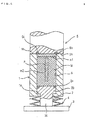
- a cylindrical die is denoted by the numeral 1.
- a lower punch 2 is provided at its upper end portion with an annular recess into which a ring-shaped backup ring 2a, made of a hard synthetic resin or the like, is fitted and is inserted into the die 1.
- An internally extending edge part 1a, formed at the lower end portion of the die 1 is engaged with a tiered part between the upper larger diameter portion 2b and a lower smaller diameter portion 2c of the lower punch 2 to prevent the die 1 from moving upward with respect to the lower punch 2.
- a support table on which the lower punch 2 is mounted is denoted by numeral 3.
- An appropriate number of disc springs 4 is provided at the smaller diameter portion 2c of the lower punch 2 between the bottom face of the die 1 and the upper surface of the support table 3.
- An upper punch 5 is provided such that the bottom face 5a thereof is placed on the upper surface 1b of the die 1.
- a backup ring 5c made of hard synthetic resin is fitted into an annular groove 5b formed in the bottom face 5a of the upper punch 5.
- the backup ring 5c is arranged so that it covers the boundary area between the die 1 and a rubber cover m1 for covering a rubber mold M described later.
- Rubber mold M can be loaded into a space formed by the die 1 and the lower punch 2 inserted therein.
- the rubber mold M has an elongated cylindrical cavity m2 to accommodate a powder P to be packed therein to produce an elongated bar-like powder compact.
- the powder P is packed into the cavity m2 of the rubber mold M.
- the rubber cover m1 is then attached.
- the upper punch 5 is lowered and placed on the upper surface 1b of the die 1.
- the upper pun ch 5 is then further lowered so that the die 1 descends together with the upper punch 5, resisting the disc springs 4 provided between the die 1 and the support table 3. While the upper punch 5 and the die 1 descend as discussed above, the lower punch 2, being held by the support table 3, does not move.
- the space 6 formed by the die 1 and the lower punch 2 is reduced in depth so that the powder particles P packed in the cavity m3 of the rubber mold M are compressed in a pseudo-isostatic manner through the rubber mold M, thereby forming an elongated cylindrical powder compact.
- the upper punch 5 is lifted and the cover m1 is detached.
- the resultant powder compact is then taken out of the rubber mold M. Meanwhile, the compact shaped in the above manner can be sintered in an appropriate manner to obtain a sintered compact.
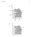
- Fig. 5 (a) illustrates for example, the rubber mold M has not yet been caught in the spaces s formed between the powder particles P, which are in contact with the rubber mold M before the pressing process is carried out by the upper punch 5 and the lower punch 2.
- Fig. 5 (b) illustrates for example, in the final pressing step by the upper punch 5 and lower punch 2, the rubber mold M is caught in the spaces s formed between the powder particles P that is in contact with the rubber mold M.
- the upper punch 5 is lifted and the pressure on the rubber mold M is released, the rubber mold M moves in the direction away from the powder compact which has been compressed while contained in the cavity m2 of the rubber mold M. Since stress is generated when the rubber mold M, which has been caught in the spaces s formed between the powder particles P in contact with the rubber mold M, is separated from the powder compact, the powder compact is cracked or chipped.
- the rubber mold M enters and leaves the spaces s formed by the powder particles P in contact with the rubber mold M.
- the rubber mold M repeatedly enters and leaves the space s, the areas of the rubber mold M which are in contact with the powder particles P are damaged. This shortens the life of the rubber mold M.
- the primary, but not sole, object of the present invention is to solve the problems mentioned above which the conventional method of producing powder compacts has suffered.
- the present invention provides a method of producing powder compacts comprising disposing a foil or film-like-like mold member packed with a powder in a cavity of a rubber mold which is loaded in a die; compressing the rubber mold, the foil or film-like type mold member and the powder packed in the foil or film-like mold member with a punch to obtain a powder compact; and subsequently using pressure to remove the powder compact with the foil or film-like mold member still being attached thereto from the rubber mold.
- the present invention also provides a method of producing powder compacts comprising disposing a foil or film-like mold member packed with a powder in a cavity of a rubber mold which is loaded in a die; compressing the rubber mold, the foil or film-like type mold member and the powder packed in the foil or film-like mold member with a punch to obtain a powder compact; subsequently removing the powder compact with the foil or film-like mold member being attached thereto by pressure from the rubber mold; and thereafter removing the foil or film-like mold member that is attached to the powder compact.
- the invention further provides a foil or film-like mold member for use in the aforementioned method of producing powder compacts, the foil or film-like mold member being provided inside a space portion into which powder can be packed.
- Figs. 1(a) and 1(b) are a perspective views of an example mold member used in the method of producing powder compacts according to the invention.
- Fig. 2 shows an elevational cross section of an apparatus for producing powder compacts for use in the method of producing powder compacts according to this invention.
- Fig. 3 shows an elevational cross section of the apparatus shown in Fig. 2.
- Fig. 4 shows an elevational cross section of an apparatus used in a conventional method of producing powder compacts.
- Figs. 5(a) and 5(b) illustrate contact states between the rubber mold and powder in the conventional apparatus for producing powder compacts shown in Fig. 4.
- foil or film-like mold members T1 and T2 are shown. These mold members are made of a soft, low melting point metal and are capable of holding a packed powder. These mold members are configured to be inserted into the cavity m2 of the rubber mold M. Specifically, Fig. 1(a) shows a foil or film-like mold member T1 made of a soft, low melting point metal and formed integrally with a bottom. Fig.
- FIG. 1(b) shows a foil or film-like mold member T2 having an integrally formed, jointless pipe t1 made of a soft, low melting point metal, and a bottom plug t2, which is made of a material such as rubber or synthetic resin or the like, is fitted into the lower opening of the bottomless pipe t1.
- the foil or film-like mold member T1 or T2 (hereinafter simply referred to as T) is inserted into the cavity m2 of the rubber mold M in the manner shown in Fig. 2 either before or after the mold member T is filled with powder P.
- the mold member T is packed with the powder P after being inserted into the cavity m2 of the rubber mold M. Then, the rubber cover m1 is mounted on the rubber mold M.
- the upper punch 5 is lowered so as to pseudo-isostatically compress the foil or film-like mold member T which has been packed with the powder P and inserted into the cavity m2 formed within the rubber mold M, thereby forming the powder P packed in the foil or film-like mold member T into a powder compact.
- the upper punch 5 is then lifted and the cover m1 is detached.
- the powder compact having the foil or film-like mold member T attached by pressure is taken out of the cavity m2 of the rubber mold M.
- the powder compact obtained through the above-mentioned process and contained in the foil or film-like mold member T may be used as it is. Otherwise, the powder compact contained in the foil or film-like mold member T may be heated at an appropriate temperature above the melting point of the foil or film-like mold member T to melt and remove the foil or film-like mold member T.
- the powder compact may be sintered to be used as a sintered compact. It is possible to heat the powder compact contained in the foil or film-like mold member T at a temperature below the melting point of the foil or film-like mold member T to obtain a presintered compact with the foil or film-like mold member T tightly attached thereto. Then, the foil or film-like mold member T can be mechanically removed from the presintered compact so that the presintered compact is fully sintered thereafter and used as a sintered compact formed in a desired shape.
- the powder P to be compressed into a compact is not packed directly in the cavity m2 of the rubber mold M. Rather, the powder P is packed in the foil or film-like mold member T. Accordingly, the problem where a part of the rubber mold M is caught in the space s formed by the powder P that is in contact with the rubber mold M does not arise during the compression by the upper punch 5. It is therefore possible to prevent the powder compact from cracking or chipping even when the rubber mold M is restored to its initial shape when the pressure is released by lifting the upper punch 5.
- the shape of the foil or film-like mold member T is designed such that a compact with a desired shape can be obtained after compaction.
- a wide variety of materials may be employed for the foil or film-like mold member T including metals such as tin, aluminum, copper, iron, nickel and stainless steel, paper and synthetic resin. The most appropriate material will be determined according to the properties, treatment temperature, or proposed use of the desired compact.
- the thickness of the foil or film-like mold member T, when it is metal is in the range of about 0.01 to 1.50 mm, and preferably, it is about 0.03 mm to 1.00 mm.
- the thickness of the foil or film-like mold member T, when it is paper or synthetic resin is in the range of about 0.05 to 3.0 mm, and preferably it is about 0.1 to 2.0 mm.
- a flat foil or film is wound around a master mold with the desired shape and bonded at the ends.
- any kind of plastic working process may be employed such as pressing, forging, drawing, and extrusion. The most appropriate process is determined according to the shape and material of the metal foil mold member T. When it is made of synthetic resin, injection molding or casting may be used.
- the foil or film-like mold member T is formed so as to closely fit into the cavity m2 of the rubber mol d M, and may or may not have a bottom.
- the above-described embodiment is arranged such that the upper punch 5 is lowered to be mounted on the upper surface of the die 1, and further lowered so as to compress the rubber mold M, foil or film-like mold member T and powder P packed in the foil or film-like mold member T.
- the arrangement may be such that with the upper punch 5 being fixed, the support table 3 provided with the lower punch 2 and die 1 is moved up and down, thereby compressing the powder into a powder compact.
- the example above shows an apparatus for compacting powder, which comprises the die 1, the lower punch 2 inserted into the die 1, the upper punch 5 to be mounted on the upper surface of the die 1, and the disc springs 4 provided at the smaller diameter portion 2c of the lower punch 2 between the bottom face of the die 1 and the upper surface of the support table 3.
- an apparatus for compacting powder which comprises a die having an opening in its upper part and a bottom, and an upper punch to be inserted into the die, in which the lower punch 2 and disc springs 4 in the above apparatus are omitted.
- the present invention provides the following effects.
- the powder to be compressed into a compact is not packed directly in the cavity of the rubber mold, but is packed in the mold member, the problem where a part of the rubber mold is caught in the space formed by the powder that is in contact with the rubber mold will not arise. Accordingly, cracking or shipping of the powder compact can be prevented even when the rubber mold is restored to its initial shape. Thus, the ranges of shape and size variations possible for the powder compact can be largely expanded.
- this invention allows coarse powders with large grain sizes to be compressed into various powder compacts, product cost can be reduced and the variety of products can be increased.
- the powder does not directly come into contact with the rubber mold in this invention. Therefore, damage to the rubber mold due to the direct contact with the powder P does not occur, thereby extending the life of the rubber mold.
- the powder compact since the powder compact is protected by the mold member, it does not suffer damage when it is ejected from the rubber mold or loaded into a sintering furnace. Handling the powder compact is therefore made easier.
Landscapes
- Engineering & Computer Science (AREA)
- Mechanical Engineering (AREA)
- Physics & Mathematics (AREA)
- Fluid Mechanics (AREA)
- Moulds For Moulding Plastics Or The Like (AREA)
- Powder Metallurgy (AREA)
- Press-Shaping Or Shaping Using Conveyers (AREA)
- Casting Or Compression Moulding Of Plastics Or The Like (AREA)
Applications Claiming Priority (4)
| Application Number | Priority Date | Filing Date | Title |
|---|---|---|---|
| JP2001175016 | 2001-06-11 | ||
| JP2001175016 | 2001-06-16 | ||
| JP2002134830 | 2002-05-10 | ||
| JP2002134830A JP2003062697A (ja) | 2001-06-11 | 2002-05-10 | 圧粉体製造方法及び該方法に使用する箔状モールド部材 |
Publications (2)
| Publication Number | Publication Date |
|---|---|
| EP1266746A2 true EP1266746A2 (de) | 2002-12-18 |
| EP1266746A3 EP1266746A3 (de) | 2003-05-02 |
Family
ID=26616664
Family Applications (1)
| Application Number | Title | Priority Date | Filing Date |
|---|---|---|---|
| EP02012406A Withdrawn EP1266746A3 (de) | 2001-06-11 | 2002-06-07 | Verfahren zur Herstellung von Pulverpresslingen und folienartigen Formteilen zur Verwendung in dem Verfahren |
Country Status (3)
| Country | Link |
|---|---|
| US (1) | US20020192102A1 (de) |
| EP (1) | EP1266746A3 (de) |
| JP (1) | JP2003062697A (de) |
Cited By (3)
| Publication number | Priority date | Publication date | Assignee | Title |
|---|---|---|---|---|
| CN102173092A (zh) * | 2011-01-27 | 2011-09-07 | 济南易久自动化技术有限公司 | 刹车片等密度多腔移动式模具 |
| CN102179951A (zh) * | 2011-01-27 | 2011-09-14 | 济南易久自动化技术有限公司 | 用于盘式刹车片等密度压制工艺和配方试验的压制机 |
| CN105856613A (zh) * | 2016-05-06 | 2016-08-17 | 江苏金泽重型机械有限公司 | 一种基于多工位粉末液压机的催泪弹传爆药柱成型模具 |
Families Citing this family (1)
| Publication number | Priority date | Publication date | Assignee | Title |
|---|---|---|---|---|
| EP1997574A1 (de) * | 2007-06-01 | 2008-12-03 | ABB Technology AG | Verfahren zur Herstellung eines Kontaktteils für eine Schaltanlage sowie eines Kontaktteils an sich |
Family Cites Families (9)
| Publication number | Priority date | Publication date | Assignee | Title |
|---|---|---|---|---|
| US3956452A (en) * | 1973-08-16 | 1976-05-11 | Shinagawa Firebrick, Co., Ltd. | Dry-type isostatic pressing method involving minimization of breaks or cracks in the molded bodies |
| JPS62191104A (ja) * | 1986-02-17 | 1987-08-21 | 株式会社神戸製鋼所 | 冷間静水圧加圧装置 |
| JPH02192470A (ja) * | 1989-01-20 | 1990-07-30 | Kobe Steel Ltd | 静水圧成形による成形体の製造方法 |
| JPH04135095A (ja) * | 1990-09-25 | 1992-05-08 | Kobe Steel Ltd | 乾式静水圧加圧成形方法及び装置 |
| JPH06100903A (ja) * | 1992-09-24 | 1994-04-12 | Kobe Steel Ltd | 粉末の等方加圧成形方法 |
| JPH09241704A (ja) * | 1996-03-12 | 1997-09-16 | Nisshin Steel Co Ltd | 粉末の冷間静水圧成形による異形成形体の作製方法 |
| JPH1046203A (ja) * | 1996-08-02 | 1998-02-17 | Inter Metallics Kk | 圧粉体成形装置 |
| JPH1080910A (ja) * | 1996-09-09 | 1998-03-31 | Ishikawajima Harima Heavy Ind Co Ltd | 薄肉成形品の成形方法 |
| JPH10216991A (ja) * | 1997-01-30 | 1998-08-18 | Kobe Steel Ltd | 粉末成形方法および装置 |
-
2002
- 2002-05-10 JP JP2002134830A patent/JP2003062697A/ja active Pending
- 2002-06-06 US US10/163,005 patent/US20020192102A1/en not_active Abandoned
- 2002-06-07 EP EP02012406A patent/EP1266746A3/de not_active Withdrawn
Cited By (5)
| Publication number | Priority date | Publication date | Assignee | Title |
|---|---|---|---|---|
| CN102173092A (zh) * | 2011-01-27 | 2011-09-07 | 济南易久自动化技术有限公司 | 刹车片等密度多腔移动式模具 |
| CN102179951A (zh) * | 2011-01-27 | 2011-09-14 | 济南易久自动化技术有限公司 | 用于盘式刹车片等密度压制工艺和配方试验的压制机 |
| CN102173092B (zh) * | 2011-01-27 | 2013-06-12 | 济南易久自动化技术有限公司 | 刹车片等密度多腔移动式模具 |
| CN105856613A (zh) * | 2016-05-06 | 2016-08-17 | 江苏金泽重型机械有限公司 | 一种基于多工位粉末液压机的催泪弹传爆药柱成型模具 |
| CN105856613B (zh) * | 2016-05-06 | 2018-11-06 | 江苏金泽重型机械有限公司 | 一种基于多工位粉末液压机的催泪弹传爆药柱成型模具 |
Also Published As
| Publication number | Publication date |
|---|---|
| US20020192102A1 (en) | 2002-12-19 |
| EP1266746A3 (de) | 2003-05-02 |
| JP2003062697A (ja) | 2003-03-05 |
Similar Documents
| Publication | Publication Date | Title |
|---|---|---|
| US3356496A (en) | Method of producing high density metallic products | |
| US4526748A (en) | Hot consolidation of powder metal-floating shaping inserts | |
| GB2125434A (en) | Producing a composite sintered article such as a compound valve seat | |
| JPH09502767A (ja) | 加圧成形品の製造方法および装置 | |
| US5490969A (en) | Mould for isostatic pressing | |
| US6592807B2 (en) | Method of making a porous tire tread mold | |
| EP1266746A2 (de) | Verfahren zur Herstellung von Pulverpresslingen und folienartigen Formteilen zur Verwendung in dem Verfahren | |
| JP2001252793A (ja) | 圧粉体の成形方法 | |
| US4255103A (en) | Hot consolidation of powder metal-floating shaping inserts | |
| KR20100014078A (ko) | 무 바인더 브리켓의 제조 방법 및 장치와, 금속 칩 및 금속분진들로 만들어진 브리켓 | |
| US4441874A (en) | Apparatus for differential expansion volume compaction | |
| US20090257904A1 (en) | Device and method for pressing a metal powder compact | |
| JP3869072B2 (ja) | 圧粉体の成形方法 | |
| JPH08302403A (ja) | 加圧成形方法 | |
| JPH0610007A (ja) | 熱間静水圧加圧成形用のカプセルおよび熱間静水圧加圧成形方法 | |
| JP2594691B2 (ja) | セラミックス管成形素地体の成形方法 | |
| JPS63286502A (ja) | 焼結成形品の圧粉成型方法 | |
| JPH0726094U (ja) | 粉末成形装置 | |
| JP2008012540A (ja) | ホットプレス | |
| JPS638728Y2 (de) | ||
| JPH01119604A (ja) | 粉末成形法 | |
| SU1595630A1 (ru) | Способ получени изделий из стружковых отходов | |
| JP2002361496A (ja) | 圧粉体成形方法及び焼結体製造方法並びに前記方法に使用する金属箔モールド | |
| JP3078356B2 (ja) | 粉末加圧成形方法 | |
| JPH10230508A (ja) | 複雑形状面を有するセッターの製造方法 |
Legal Events
| Date | Code | Title | Description |
|---|---|---|---|
| PUAI | Public reference made under article 153(3) epc to a published international application that has entered the european phase |
Free format text: ORIGINAL CODE: 0009012 |
|
| AK | Designated contracting states |
Kind code of ref document: A2 Designated state(s): AT BE CH CY DE DK ES FI FR GB GR IE IT LI LU MC NL PT SE TR |
|
| AX | Request for extension of the european patent |
Free format text: AL;LT;LV;MK;RO;SI |
|
| PUAL | Search report despatched |
Free format text: ORIGINAL CODE: 0009013 |
|
| AK | Designated contracting states |
Designated state(s): AT BE CH CY DE DK ES FI FR GB GR IE IT LI LU MC NL PT SE TR |
|
| AX | Request for extension of the european patent |
Extension state: AL LT LV MK RO SI |
|
| AKX | Designation fees paid | ||
| REG | Reference to a national code |
Ref country code: DE Ref legal event code: 8566 |
|
| STAA | Information on the status of an ep patent application or granted ep patent |
Free format text: STATUS: THE APPLICATION IS DEEMED TO BE WITHDRAWN |
|
| 18D | Application deemed to be withdrawn |
Effective date: 20031104 |