EP1266818A2 - Structure avant de véhicule - Google Patents
Structure avant de véhicule Download PDFInfo
- Publication number
- EP1266818A2 EP1266818A2 EP02013458A EP02013458A EP1266818A2 EP 1266818 A2 EP1266818 A2 EP 1266818A2 EP 02013458 A EP02013458 A EP 02013458A EP 02013458 A EP02013458 A EP 02013458A EP 1266818 A2 EP1266818 A2 EP 1266818A2
- Authority
- EP
- European Patent Office
- Prior art keywords
- vehicle body
- carrier
- frame
- fitting
- vehicle
- Prior art date
- Legal status (The legal status is an assumption and is not a legal conclusion. Google has not performed a legal analysis and makes no representation as to the accuracy of the status listed.)
- Granted
Links
- 238000001816 cooling Methods 0.000 claims abstract description 6
- 230000035939 shock Effects 0.000 claims description 34
- 239000006096 absorbing agent Substances 0.000 claims description 33
- 210000002414 leg Anatomy 0.000 description 18
- 210000003195 fascia Anatomy 0.000 description 6
- 238000000034 method Methods 0.000 description 5
- 238000005187 foaming Methods 0.000 description 4
- 210000000629 knee joint Anatomy 0.000 description 4
- 239000004033 plastic Substances 0.000 description 4
- 229920003023 plastic Polymers 0.000 description 4
- 238000005452 bending Methods 0.000 description 3
- 238000005516 engineering process Methods 0.000 description 3
- 230000008569 process Effects 0.000 description 3
- 238000004378 air conditioning Methods 0.000 description 2
- 210000003141 lower extremity Anatomy 0.000 description 2
- 239000004743 Polypropylene Substances 0.000 description 1
- 229920005830 Polyurethane Foam Polymers 0.000 description 1
- 208000027418 Wounds and injury Diseases 0.000 description 1
- 230000015572 biosynthetic process Effects 0.000 description 1
- 230000008859 change Effects 0.000 description 1
- 230000006378 damage Effects 0.000 description 1
- 239000006260 foam Substances 0.000 description 1
- 208000014674 injury Diseases 0.000 description 1
- 238000003780 insertion Methods 0.000 description 1
- 230000037431 insertion Effects 0.000 description 1
- 239000003562 lightweight material Substances 0.000 description 1
- 239000000463 material Substances 0.000 description 1
- 230000002093 peripheral effect Effects 0.000 description 1
- -1 polypropylene Polymers 0.000 description 1
- 229920001155 polypropylene Polymers 0.000 description 1
- 239000011496 polyurethane foam Substances 0.000 description 1
- 230000009467 reduction Effects 0.000 description 1
- 230000007480 spreading Effects 0.000 description 1
- 239000013585 weight reducing agent Substances 0.000 description 1
- 238000003466 welding Methods 0.000 description 1
Images

Classifications
-
- B—PERFORMING OPERATIONS; TRANSPORTING
- B62—LAND VEHICLES FOR TRAVELLING OTHERWISE THAN ON RAILS
- B62D—MOTOR VEHICLES; TRAILERS
- B62D25/00—Superstructure or monocoque structure sub-units; Parts or details thereof not otherwise provided for
- B62D25/08—Front or rear portions
- B62D25/082—Engine compartments
- B62D25/084—Radiator supports
-
- B—PERFORMING OPERATIONS; TRANSPORTING
- B60—VEHICLES IN GENERAL
- B60R—VEHICLES, VEHICLE FITTINGS, OR VEHICLE PARTS, NOT OTHERWISE PROVIDED FOR
- B60R19/00—Wheel guards; Radiator guards, e.g. grilles; Obstruction removers; Fittings damping bouncing force in collisions
- B60R19/02—Bumpers, i.e. impact receiving or absorbing members for protecting vehicles or fending off blows from other vehicles or objects
- B60R19/04—Bumpers, i.e. impact receiving or absorbing members for protecting vehicles or fending off blows from other vehicles or objects formed from more than one section in a side-by-side arrangement
- B60R19/12—Bumpers, i.e. impact receiving or absorbing members for protecting vehicles or fending off blows from other vehicles or objects formed from more than one section in a side-by-side arrangement vertically spaced
-
- B—PERFORMING OPERATIONS; TRANSPORTING
- B60—VEHICLES IN GENERAL
- B60R—VEHICLES, VEHICLE FITTINGS, OR VEHICLE PARTS, NOT OTHERWISE PROVIDED FOR
- B60R19/00—Wheel guards; Radiator guards, e.g. grilles; Obstruction removers; Fittings damping bouncing force in collisions
- B60R19/02—Bumpers, i.e. impact receiving or absorbing members for protecting vehicles or fending off blows from other vehicles or objects
- B60R19/24—Arrangements for mounting bumpers on vehicles
-
- B—PERFORMING OPERATIONS; TRANSPORTING
- B60—VEHICLES IN GENERAL
- B60R—VEHICLES, VEHICLE FITTINGS, OR VEHICLE PARTS, NOT OTHERWISE PROVIDED FOR
- B60R19/00—Wheel guards; Radiator guards, e.g. grilles; Obstruction removers; Fittings damping bouncing force in collisions
- B60R19/02—Bumpers, i.e. impact receiving or absorbing members for protecting vehicles or fending off blows from other vehicles or objects
- B60R19/18—Bumpers, i.e. impact receiving or absorbing members for protecting vehicles or fending off blows from other vehicles or objects characterised by the cross-section; Means within the bumper to absorb impact
- B60R2019/1806—Structural beams therefor, e.g. shock-absorbing
- B60R2019/1813—Structural beams therefor, e.g. shock-absorbing made of metal
-
- B—PERFORMING OPERATIONS; TRANSPORTING
- B60—VEHICLES IN GENERAL
- B60R—VEHICLES, VEHICLE FITTINGS, OR VEHICLE PARTS, NOT OTHERWISE PROVIDED FOR
- B60R19/00—Wheel guards; Radiator guards, e.g. grilles; Obstruction removers; Fittings damping bouncing force in collisions
- B60R19/02—Bumpers, i.e. impact receiving or absorbing members for protecting vehicles or fending off blows from other vehicles or objects
- B60R19/18—Bumpers, i.e. impact receiving or absorbing members for protecting vehicles or fending off blows from other vehicles or objects characterised by the cross-section; Means within the bumper to absorb impact
- B60R2019/186—Additional energy absorbing means supported on bumber beams, e.g. cellular structures or material
- B60R2019/1873—Cellular materials
-
- B—PERFORMING OPERATIONS; TRANSPORTING
- B60—VEHICLES IN GENERAL
- B60R—VEHICLES, VEHICLE FITTINGS, OR VEHICLE PARTS, NOT OTHERWISE PROVIDED FOR
- B60R21/00—Arrangements or fittings on vehicles for protecting or preventing injuries to occupants or pedestrians in case of accidents or other traffic risks
- B60R21/34—Protecting non-occupants of a vehicle, e.g. pedestrians
Definitions
- the present invention relates to a front end structure of a vehicle, more particularly to the front end structure of a vehicle body frame equipped with a module carrier.
- a front end of the vehicle body frame is joined to and incorporated into front side members provided on right and left sides of a vehicle body and a front wheel apron by welding. Accordingly, an engine room is formed into a box shape with opening provided on top and bottom sides thereof. For this reason, in an assembly process, an operator is forced to perform the prosess in uncomfortable positions such as looking into the engine room from above or below the vehicle body.
- radiator panel constituting the front end is damaged by a light collision on a front side, it is not possible to replace just only the radiator panel because the front end is formed integrally with the vehicle body frame. As a consequence, work procedures for replacement of components are increased and the number of components for replacement is also increased, whereby too much expense is incurred upon such replacement.
- the front end panel is provided separately from the vehicle body frame and the front end panel is detached from the vehicle body frame in the assembly process so as to effectuate the assembly operations from the front of the vehicle body into an engine room.
- assembled components such as a radiator and headlamps are fitted onto the front end panel to form a modularized front end panel.
- the modularized front end panel is fixed onto the vehicle body frame by bolts or the like.
- Japanese Patent Application Laid-Open No. Hei. 7-172345 discloses a technology, in which the front end panel is fixed onto a bumper beam extending in a widthwise direction of the vehicle, and bosses protruding backward from both ends of the bumper beam are fastened to front side members with the bolts, whereby the front end panel is sandwiched and fixed between the bumper beam and a vehicle body frame.
- the front end panel is just sandwiched and fixed between front end faces of the front side members and the bumper beam. Therefore, if an impact is applied from the front to a lower end of the front end panel, a large bending moment is generated at a portion sandwiched between the front side members and the bumper beam as a pivot. Therefore, the prior art has a problem of weak strength because sufficient resistance against an impact load cannot be obtained.
- a front end structure of a vehicle including at least a part of a front end panel being modularized as separate components, in which rigidity against an impact load to be applied from a front side of a vehicle body to a lower end of the modularized part is enhanced so as to receive the impact load positively, and the front end structure being capable of protecting a leg of a pedestrian.
- an aspect of the present invention is characterized by the front end structure of the vehicle, in which a module carrier is formed with a carrier upper frame and a carrier lower frame each extending in a widthwise direction of the vehicle and a stay extending in a vertical direction to connect both side ends of the two frames, and the module carrier is fixed onto a front part of a vehicle body frame to constitute at least a part of a front end.
- the front end structure includes a first fitting face which is provided on the stay, and a second fitting face which is provided on a side closer to a rear end of the vehicle body than the first fitting face, and the both fitting faces are fixed onto the vehicle body frame.
- the first fitting face provided on the stay which constitutes the module carrier, and the second fitting face positioned closer to the rear end of the vehicle body than the first fitting face are fixed onto the vehicle body frame, whereby a lower part of the module carrier is supported on the vehicle body frame with a truss structure. Accordingly, the module carrier can receive an impact load being applied from the front of the vehicle body to the carrier lower frame.
- the present invention is characterized by a front bumper beam extending in the widthwise direction of the vehicle and being fastened to the vehicle body frame so as to sandwich the first fitting face together with the vehicle body frame.
- the front bumper beam being temporarily fitted onto the first fitting face with a temporary fastener, and a pilot pin being provided on a tip of the temporary fastener so as to be engaged into a pilot hole formed on a front portion of the vehicle body frame.
- the front bumper beam being temporarily fitted onto the first fitting face with a temporary fastener, a pilot member being formed to protrude from a front edge of the vehicle body frame, and a pilot hole to be engaged with the pilot member being formed on at least any one of the first fitting face and the front bumper beam.
- a front part of the carrier lower frame protruded further forward of the vehicle body than a front part of the carrier upper frame, an upper stage shock absorber being provided on a front face of the front bumper beam, a lower stage shock absorber being provided on a front face of the carrier lower frame, and rigidity in a longitudinal(back-to-front) direction of the lower stage shock absorber being setted higher than the rigidity of the upper stage shock absorber.
- auxiliary components of a cooling system being integrated on the module carrier.
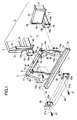
- Fig. 1 is an exploded perspective view of a front end of a vehicle
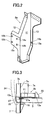
- Fig. 2 is a perspective view of a stay on a right side of a vehicle body
- Fig. 3 is a cross-sectional view taken along the line III-III in Fig 1
- Fig. 4 is a cross-sectional view taken along the line IV-IV in Fig. 1.
- Reference numeral 1 in Fig. 1 denotes a frontal vehicle body frame constituting a vehicle body frame.
- Front wheel aprons 2 are formed on both sides of the frontal vehicle body frame 1 in a widthwise direction of the vehicle so as to define both sides of an engine room.
- front side members 3 are provided on the right and the left at bottoms of the front wheel aprons 2.
- front end portions 2c including headlamp fitting portions 2b are joined to the front of the front wheel aprons 2 on the right and the left sides.
- An opening 4 is formed between the front end portions 2c.
- a frontal edge of the front side member 3 protrudes further forward than the front end portion 2c, and a module carrier 5, which constitutes a front end panel together with the front end portions 2c, is fitted and fixed onto the both front side members 3 so as to place at the opening 4.
- the module carrier 5 includes a carrier upper frame 6 and a carrier lower frame 7 on the top and the bottom thereof.
- the carrier upper frame 6 and the carrier lower frame 7 are joined with a pair of stays 8a and 8b disposed on both sides of the frames 6 and 7, thus constituting an integrated frame structure.
- the module carrier 5 may be also an integrally molded member using plastics or the like.
- the module carrier 5 is fitted onto the frontal vehicle body frame 1 so as to place at the opening 4 between the front end portions 2c.
- auxiliary components for a cooling system which are represented by a radiator unit 9 including a radiator and an air-conditioning condenser, a cooling fan 10 to be fixed at the back of the foregoing members, and the like, are fixed thereto in an assembled state.
- the module carrier 5 is modularized in advance.
- the stays 8a and 8b of the module carrier 5 have mutually symmetrical shapes, each of which is bent and formed into a Z-shaped cross section.
- frontal flanges 12 are formed to bend outward.
- back flanges 13 are formed behind the vertical wall surfaces 11 so as to bend inward.
- a front fitting face 12a as a first fitting face is formed on the midway of each of the frontal flanges 12.
- an upper portion of the frontal flange 12 of each of the stays 8a and 8b is formed into a tapered shape spreading downward, so that the upper portion is formed continuously to the front fitting face 12a.
- a lower portion of the frontal flange 12 extends vertically downward from the front fitting face 12a.
- a portion of the back flange 13 which is lower than a position corresponding to the front fitting face 12a is formed into a tapered shape extending downward. Therefore, regarding the vertical wall surface 11, a second width W2 between the front fitting face 12a and a back fitting face 13a is formed wider than a first width W1 of a lower part of the vertical wall surface 11.
- the back flange 13 positioned on the back of the front fitting face 12a constitutes the back fitting face 13a as a second fitting face, and a bolt inserting hole 13b as shown in Fig. 2 is drilled on the second fitting face 13a.
- the bolt inserting holes 12b are drilled on upper and lower outsides of the front fitting face 12a and on a lower inside thereof.
- a screw hole 12c is drilled on an upper inside thereof.
- the carrier upper frame 6 is formed to have a groove cross section and a downward opening, and upper ends of the stays 8a and 8b are fitted and joined inside the opening.
- the carrier lower frame 7 is formed to have the groove cross section and the backward opening.
- a bottom frame 7a of the carrier lower frame 7 extends further backward than an upper frame 7b thereof.
- the radiator unit 9 is mounted on the bottom frame 7a.
- a flange 7c is formed on a back end of the upper frame 7b of the carrier lower frame 7 so as to bend upward.
- hatched regions on upper ends of the stays 8a and 8b are joined to an inner surface of the carrier upper frame 6. Moreover, hatched regions on lower parts of the stays 8a and 8b are joined to the flange 7c formed on the carrier lower frame 7.
- Radiator fitting brackets 15 for fixing an upper surface of the radiator unit 9 are fixed onto a front face of the carrier upper frame 6.
- a latch fitting bracket 16 is fixed in the center of the carrier upper frame 6.
- a latch to be fixed onto the latch fitting bracket 16 and a hood striker (not shown) to be fixed onto a front end of an engine hood 17 (see Fig. 4) collectively constitute a hood locking system.
- a closed state of the engine hood is maintained by retaining the hood striker with the latch.
- member plates 18 for abutting on the front fitting face 12a are fixed on the respective front side members 3.
- screw holes 18a which correspond to the bolt-inserting holes 12b drilled on the front fitting face 12a, and a pilot hole 18b corresponding to the screw hole 12c.
- a lower end of a frame 19 with a hat-shaped cross section is fixed on each of side faces of the front side members 3 opposite to each other.
- An upper end of the frame 19- is fixed onto an opposite end of the headlamp fitting portion 2b.
- a member bracket 20 On mutually opposite faces at lower parts of the both frames 19, fixed is a member bracket 20 to abut on the second fitting faces 13a provided on the back flanges 13, which constitute the stays 8a and 8b.
- a distance between the member plate 18 fixed onto the front face of the front side member 3 and the member bracket 20 is setted to an almost equal dimension as the second width W2 of the stay 8a or 8b. Accordingly, when the module carrier 5 is placed in the opening 4, a back face of the front fitting face 12a abuts on the member plate 18 and a back face of the second fitting face 13a abuts on the member bracket 20. A weld nut 20a is fixed onto a back face of the member bracket 20 (see Fig. 4). Note that bolt-inserting holes 21 are drilled on the carrier upper frame 6 so that the carrier upper frame 6 is fastened to an upper face of the headlamp fitting portion 2b directly or via a bracket (not shown) with bolts.
- a bolt 27 with a pilot pin 27a formed integrally at its tip is passed through and screwed into the bolt-inserting hole 25a drilled on the beam bracket 25 of the front bumper beam 24, whereby a tip of the pilot pin 27a protrudes out-of the back face of the front fitting face 12a backward.
- an upper-stage shock absorber 28 and a lower-stage shock absorber 29 abut on front faces of the front bumper beam 24 and the carrier lower frame 7, respectively.
- Front sides of the shock absorbers 28 and 29 are covered with a bumper fascia 30 made of an elastic member such as plastics.
- the shock absorbers 28 and 29 are made of foamed materials having given foaming factors, such as polyurethane foam or polypropylene foam.
- the upper-stage shock absorber 28 is disposed in a position almost corresponding to a knee joint of a leg of a pedestrian (a leg impacter K for hitting test is illustrated as a model of a human leg in the drawing).
- a foaming factor and a cross-sectional area of the upper stage shock absorber 28 are setted such that the shock absorber 28 is deformed to absorb the shock applied to the knee joint when the front of the vehicle body hits the leg of the pedestrian.
- the lower stage shock absorber 29 absorbs an impact energy against rigid members such as wall faces and the vehicle, a foaming factor and a cross-sectional area of the lower stage shock absorber 29 are setted to create higher rigidity than that of the upper stage shock absorber 28 in a longitudinal direction of the vehicle body, so as to scoop up a lower leg of the pedestrian responsive to an impact.
- an impact load to be transmitted from the lower stage shock absorber 29 is received by the carrier lower frame 7 which supports the lower stage shock absorber 29. Accordingly, a front part of the carrier lower frame 7 protrudes forward so that a sufficient reactive force can be transferred to the lower stage shock absorber 29. Note that a front edge of the carrier lower frame 7 is setted at a slightly backward position from a front end of the front bumper beam 24 in this embodiment.
- radiator unit 9 including the radiator and the air-conditioning condenser are fitted onto the module carrier 5 in advance, whereby these components are modularized beforehand.
- the front bumper beam 24 is fitted temporarily to a front part of the module carrier 5. Now, procedures for temporarily fitting the front bumper beam 24 will be described in the following.
- the beam brackets 25 fixed onto both sides of the front bumper beam 24 are allowed to abut on the front fitting faces 12a formed in front of the stays 8a and 8b arranged on the both sides of the module carrier 5.
- the bolts 27 are inserted from the front side of the vehicle body into the bolt-inserting holes 25a drilled on the upper part of the inner side thereof out of the bolt-inserting holes 25a drilled on the beam bracket 25.
- the bolt 27 is screwed into the screw hole 12c drilled on the front fitting faces 12a of each of the stays 8a and 8b, and the front bumper beam 24 is thereby fitted temporarily to the module carrier 5.
- the pilot pin 27a formed on the tip of each bolt 27 protrudes backward from the back face of the second fitting face 12a.
- the vehicle body frame traveling on an assembly line has the opening 4, which is provided between the front end portions 2c. Accordingly, it is possible to perform inserting into an engine room not only from top and bottom directions of the vehicle body but also from a frontal direction thereof.
- the module carrier 5 in which the peripheral auxiliary components for the cooling system are integrated and modularized in advance, is placed at the opening 4 provided between the front end portions 2c.
- the pilot pins 27a of the bolt 27 protruding from the back faces of the second fitting faces 12a provided on the module carrier 5 are inserted into the pilot holes 18b on the member plates 18 fixed onto the front ends of the front side members 3 of the front vehicle body frame 1.
- the module carrier 5 is piloted to the space between the front end portions 2c, whereby the back faces of the front fitting faces 12a abut on the member plates 18 provided on the tips of the front side members 3, and the back faces of the second fitting faces 13a abut on the member brackets 20 fixed onto the side faces of the front side members 3.
- the respective bolt-inserting holes 25a drilled on the beam brackets 25 and the respective bolt-inserting holes 12b drilled on the front fitting faces 12a coincide with the screw holes 18a drilled on the member plates 18.
- the bolt-inserting holes 13b drilled on the second fitting faces 13a coincide with the weld nuts 20a fixed onto the member brackets 20.
- the relatively rigid front bumper beam 24 supports the bolts 27 with the pilot pin. Accordingly, if a distance between the pair of the front side members 3 is fluctuated to some extent, such fluctuation can be corrected by inserting the pilot pins 27a on the module carrier 5 into the pilot holes 18b on the front bumper beam 24.
- bolts (not shown) are inserted into three bolt-inserting holes 25a drilled on each of the beam brackets 25 except the bolt-inserting hole 25a where the bolt 27 is inserted, and into the bolt-inserting holes 12b drilled on each of the front fitting faces 12a, whereby the bolts are further screwed into the screw holes 18a provided on each of the member plates 18.
- the front fitting faces 12a of the modular carrier 5 are attached and fixed between the member plates 18 and the beam brackets 25.
- the bolts inserted into the bolt-inserting holes 13b drilled on the back fitting faces 13a are further screwed into the weld nuts 20a fixed onto the member brackets 20 in order to fix the back fitting faces 13a.
- both ends of the carrier upper frame 6 are fixed onto the front end portions 2c either directly or via brackets (not shown).
- the both shock absorbers 28 and 29 are covered with the bumper fascia 30, which constitutes a part of a shape of the vehicle body.
- an upper part and a lower part of the bumper fascia 30 are fixed onto the module carrier 5 and to the front end portions 2c to complete assembly around the front end panel.
- the lower part of the bumper fascia 30 may be allowed to extend downward under the bottom frame 7a of the carrier lower frame 7 and fixed onto the bottom frame 7a with clips or bolts.
- the leg impacter K hits the front of the vehicle body, a part of the upper stage shock absorber 28 colliding on the vicinity of the knee joint of the leg impacter K is subjected to plastic deformation, whereby the impact energy upon collision is absorbed.
- the lower stage shock absorber 29 has more rigidity than that of the upper stage shock absorber 28, which is attributable to a formation under a lower foaming factor than the upper stage shock absorber 28.
- the front end face of the carrier lower frame 7 abutting on the back face of the lower stage shock absorber 29 protrudes to the position being slightly setted back from the front end face of the front bumper beam 24. Accordingly, a thickness of the lower stage shock absorber 29 is reduced and an amount of the deformation upon receipt of the impact is thereby suppressed.
- the front end face of the carrier lower frame 7 can receive the impact load received by the lower stage shock absorber 29, and a sufficient reactive force against the leg can be generated.
- the rigidity on the lower part of the bumper fascia 30 can be enhanced by fixing the lower part to the bottom frame 7a with the clips or the bolts. Accordingly, the bumper fascia 30 can also generate some reactive force by its own rigidity.
- an upper part of the leg impacter K is inclined onto the engine hood 17 of the vehicle body owing to the deformation of the upper stage shock absorber 28, and a lower part of the leg impacter K is scooped up by the reactive force of the lower stage shock absorber 29. Accordingly, it is possible to protect the lower leg of the pedestrian from injury.
- the impact load eventually causes bending moments on the stays 8a and 8b fixing the carrier lower frame 7 on the lower ends thereof, in a counterclockwise direction according to Fig. 4 while taking the front fitting faces 12a as pivots.
- the back fitting faces 13a which are formed closer to the rear end than that of the front fitting faces 12a, are fixed onto the member brackets 20 being fixed onto the front side members 3.
- the second width W2 between the front fitting face 12a and the back fitting face 13a is formed wider than the first width W1 at the lower part of the vertical wall surface 11. Therefore, the lower parts of the stays 8a and 8b are supported by truss structures against the front side members 3, and the stays 8a and 8b can receive the impact load applied from the carrier lower frame 7 securely with an increased strength.
- the bolt 27 may be substituted by an eyebolt associated with a pilot pin. Use of such eyebolt can impart a pulling function as well. Otherwise, a screw hole may be provided on a head of the bolt 27 so as to effectively engage the eyebolt.
- the module carrier may include an entire front end panel including the headlamp fitting portions.
- pins or bolts having piloting functions may be provided on the front ends of the front side members 3 in a protruding manner, and the pilot holes for allowing insertions of the foregoing pins or bolts may be drilled on the front fitting faces 12a formed on the stays 8a and 8b constituting the module carrier 5 and on the beam brackets 25.
- the part of the front end panel is composed of the module carrier of separate components, rigidity against the impact load applied from the front side of the vehicle body to the lower end of the module carrier can be enhanced so as to receive the impact load firmly.
- the rigidity against the impact load is enhanced, the sufficient reactive force can be generated against the impact load if the front of the vehicle body hits the leg of the pedestrian. Such reactive force is effective for scooping up the leg of the pedestrian, and the leg can be thereby protected.
Landscapes
- Engineering & Computer Science (AREA)
- Mechanical Engineering (AREA)
- Chemical & Material Sciences (AREA)
- Combustion & Propulsion (AREA)
- Transportation (AREA)
- Body Structure For Vehicles (AREA)
Applications Claiming Priority (2)
| Application Number | Priority Date | Filing Date | Title |
|---|---|---|---|
| JP2001182043 | 2001-06-15 | ||
| JP2001182043A JP4762444B2 (ja) | 2001-06-15 | 2001-06-15 | 車両のフロントエンド構造 |
Publications (3)
| Publication Number | Publication Date |
|---|---|
| EP1266818A2 true EP1266818A2 (fr) | 2002-12-18 |
| EP1266818A3 EP1266818A3 (fr) | 2003-03-12 |
| EP1266818B1 EP1266818B1 (fr) | 2006-08-09 |
Family
ID=19022211
Family Applications (1)
| Application Number | Title | Priority Date | Filing Date |
|---|---|---|---|
| EP02013458A Expired - Lifetime EP1266818B1 (fr) | 2001-06-15 | 2002-06-13 | Structure avant de véhicule |
Country Status (4)
| Country | Link |
|---|---|
| US (1) | US6672652B2 (fr) |
| EP (1) | EP1266818B1 (fr) |
| JP (1) | JP4762444B2 (fr) |
| DE (1) | DE60213714T2 (fr) |
Cited By (20)
| Publication number | Priority date | Publication date | Assignee | Title |
|---|---|---|---|---|
| FR2849422A1 (fr) * | 2002-12-26 | 2004-07-02 | Renault Sa | Partie extreme avant du chassis d'un vehicule automobile |
| EP1527957A1 (fr) * | 2003-10-28 | 2005-05-04 | Mitsubishi Fuso Truck and Bus Corporation | Structure de véhicule amortissant l'impact |
| WO2007011238A1 (fr) * | 2005-07-22 | 2007-01-25 | Norsk Hydro Asa | Systeme de protection contre les accidents |
| EP1754652A1 (fr) * | 2005-08-18 | 2007-02-21 | MAN Nutzfahrzeuge Aktiengesellschaft | Câssis du véhicule pour une véhicule utilitaire. |
| EP1754650A1 (fr) * | 2005-08-20 | 2007-02-21 | HBPO GmbH | Face avant technique avec support d'assemblage avec poutre basse |
| WO2007085582A1 (fr) * | 2006-01-26 | 2007-08-02 | Faurecia Kunststoffe Automobilsysteme Gmbh | Longeron de véhicule automobile et unité frontale de véhicule automobile |
| EP1754654A3 (fr) * | 2005-08-20 | 2008-06-25 | HBPO GmbH | Raccord à brides pour visser un boîtier absorbeur d'énergie et un porte-montage à un longeron de véhicule |
| FR2910865A1 (fr) * | 2006-12-28 | 2008-07-04 | Plastic Omnium Cie | Piece d'appui pour systeme d'absorption de chocs destinee a etre montee en bout d'un longeron d'un vehicule automobile |
| WO2009013416A1 (fr) * | 2007-07-26 | 2009-01-29 | Peugeot Citroën Automobiles SA | Procede de montage d'un pare-chocs sur une structure de vehicule automobile. |
| DE102004030794B4 (de) * | 2004-06-25 | 2009-05-07 | Hbpo Gmbh | Fahrzeugfrontendmodul mit Fußgängerschutzvorrichtung |
| EP1800960A3 (fr) * | 2005-12-21 | 2009-05-13 | Kojima Press Industry Co., Ltd. | Appareil de protection de piéton pour véhicule |
| EP2138381A1 (fr) * | 2008-06-26 | 2009-12-30 | MAN Nutzfahrzeuge Aktiengesellschaft | Support transversal frontal d'un véhicule utilitaire |
| DE102011119542A1 (de) * | 2011-11-26 | 2013-05-29 | Volkswagen Aktiengesellschaft | Frontendmodul für ein Kraftfahrzeug |
| WO2016120011A1 (fr) * | 2015-01-27 | 2016-08-04 | Daimler Ag | Module avant pour une voiture particulière |
| EP3040255A4 (fr) * | 2013-08-30 | 2017-06-21 | Honda Motor Co., Ltd. | Structure pour l'avant d'une carrosserie de véhicule |
| US20220212724A1 (en) * | 2021-01-06 | 2022-07-07 | Hyundai Motor Company | Radiator support assembly |
| FR3119129A1 (fr) * | 2021-01-28 | 2022-07-29 | Psa Automobiles Sa | Structure avant de véhicule automobile comportant une traverse supérieure et véhicule comportant une telle structure avant |
| US20220314911A1 (en) * | 2021-03-30 | 2022-10-06 | Subaru Corporation | Vehicle shock absorbing structure |
| US20220379965A1 (en) * | 2021-05-25 | 2022-12-01 | Mazda Motor Corporation | Vehicle front body structure |
| FR3137044A1 (fr) * | 2022-06-23 | 2023-12-29 | Psa Automobiles Sa | Structure avant d’un véhicule automobile et véhicule automobile pourvu d’une telle structure avant |
Families Citing this family (46)
| Publication number | Priority date | Publication date | Assignee | Title |
|---|---|---|---|---|
| JP2001121941A (ja) * | 1999-10-28 | 2001-05-08 | Denso Corp | 熱交換器の車両搭載構造 |
| FR2800695B1 (fr) * | 1999-11-08 | 2001-12-07 | Renault | Vehicule, notamment de tourisme, a structure d'encaissement de choc anti-chevauchement |
| JP4605849B2 (ja) * | 2000-03-30 | 2011-01-05 | 富士重工業株式会社 | 車体前部構造 |
| GB0114684D0 (en) * | 2001-06-15 | 2001-08-08 | Dow Chemical Co | Automobile assembly |
| JP4192452B2 (ja) * | 2001-09-18 | 2008-12-10 | トヨタ自動車株式会社 | 車両のフェンダ構造 |
| US6974166B2 (en) * | 2002-01-18 | 2005-12-13 | Transfreight Technology, Llc | Adjustable safety bumper |
| JP2003252242A (ja) * | 2002-02-26 | 2003-09-10 | Denso Corp | 車両のフロントエンド構造 |
| JP4026465B2 (ja) * | 2002-03-11 | 2007-12-26 | 株式会社デンソー | 車両の前端構造 |
| JP4349115B2 (ja) * | 2003-02-26 | 2009-10-21 | 日産自動車株式会社 | フレーム車の車体前部構造 |
| US6935669B2 (en) * | 2003-11-04 | 2005-08-30 | Jay Staines | Retrofittable storage container adapted for placement under the hood of a motorized vehicle |
| JP4586477B2 (ja) * | 2003-12-22 | 2010-11-24 | マツダ株式会社 | シュラウドの支持構造および組付け方法 |
| US6948769B2 (en) * | 2003-12-22 | 2005-09-27 | Nissan Technical Center North America, Inc. | Vehicle front end structure |
| KR100577814B1 (ko) * | 2004-05-17 | 2006-05-11 | 현대모비스 주식회사 | 자동차의 프런트엔드모듈(FEM;front endmodule)상부판넬의 수평래치 결합구조 |
| US7066533B2 (en) * | 2004-06-03 | 2006-06-27 | Ford Global Technologies, Llc | Tubular front end structure for automobiles and method for making the same |
| JP4424208B2 (ja) * | 2005-01-17 | 2010-03-03 | トヨタ自動車株式会社 | 車体の前部構造 |
| JP4207904B2 (ja) * | 2005-02-28 | 2009-01-14 | トヨタ自動車株式会社 | 車両端部構造 |
| KR101160355B1 (ko) | 2005-03-15 | 2012-06-26 | 한라공조주식회사 | 자동차용 충격흡수 프로텍터 |
| JP4434081B2 (ja) | 2005-06-07 | 2010-03-17 | トヨタ自動車株式会社 | 車両端部構造 |
| US20070150482A1 (en) * | 2005-08-12 | 2007-06-28 | Jacob Taylor | Customer relationship management system and method |
| DE102005059447A1 (de) * | 2005-12-13 | 2007-06-14 | GM Global Technology Operations, Inc., Detroit | Stoßfängersystem für ein Kraftfahrzeug |
| US7419208B2 (en) * | 2006-02-03 | 2008-09-02 | Halla Climate Control Corp. | Carrier for front end module of vehicle |
| US8141918B2 (en) * | 2006-02-24 | 2012-03-27 | Honda Motor Co., Ltd. | Pedestrian bumper system and method |
| US20070236049A1 (en) * | 2006-03-31 | 2007-10-11 | Dow Global Technologies Inc. | Modular assembly for a vehicle |
| US20070267241A1 (en) * | 2006-05-05 | 2007-11-22 | Textron Inc. | Small utility vehicle frame with prevailing torque weld nuts |
| US7926870B2 (en) * | 2006-05-26 | 2011-04-19 | Dow Global Technologies Llc | Modular assembly for a vehicle |
| ITBO20060487A1 (it) * | 2006-06-23 | 2007-12-24 | Ferrari Spa | Paraurti anteriore per una automobile |
| US7571957B2 (en) * | 2007-02-01 | 2009-08-11 | Magna International | Component integration panel system with closed box section |
| JP2008195094A (ja) * | 2007-02-08 | 2008-08-28 | Honda Motor Co Ltd | 車両の車体前部構造 |
| KR100867700B1 (ko) * | 2007-07-27 | 2008-11-10 | 현대자동차주식회사 | 보행자 보호를 위한 차량 전방의 구조물 |
| JP5077541B2 (ja) * | 2007-08-29 | 2012-11-21 | スズキ株式会社 | 車体前部構造 |
| FR2931417B1 (fr) * | 2008-05-22 | 2011-02-25 | Valeo Systemes Thermiques Branche Thermique Moteur | Dispositif d'absorption de choc et face avant comportant un tel dispositif |
| DE102008039972A1 (de) * | 2008-08-27 | 2010-03-04 | Dr.Ing.H.C.F.Porsche Aktiengesellschaft | Frontstruktur eines Kraftfahrzeugs |
| US7878579B2 (en) * | 2008-10-22 | 2011-02-01 | Honda Motor Co., Ltd. | Vehicle front end assembly and method |
| DE102009009882B4 (de) * | 2009-02-20 | 2022-10-13 | Dr. Ing. H.C. F. Porsche Aktiengesellschaft | Frontenmodul für ein Kraftfahrzeug |
| DE102009031777A1 (de) * | 2009-07-06 | 2011-01-13 | GM Global Technology Operations, Inc., Detroit | Vorderteil für eine Kraftfahrzeugkarosserie |
| KR101606474B1 (ko) * | 2009-11-23 | 2016-03-25 | 현대모비스 주식회사 | 보행자 보호장치 |
| JP5440207B2 (ja) * | 2010-01-22 | 2014-03-12 | スズキ株式会社 | 車体前部構造 |
| DE102010021574A1 (de) * | 2010-05-26 | 2011-12-01 | Gm Global Technology Operations Llc (N.D.Ges.D. Staates Delaware) | Vorderbau für ein Kraftfahrzeug |
| KR101781921B1 (ko) * | 2012-02-23 | 2017-09-26 | 한온시스템 주식회사 | 차량용 캐리어 |
| CN105235753B (zh) * | 2015-10-27 | 2017-09-12 | 奇瑞商用车(安徽)有限公司 | 一种前保安装结构 |
| JP6278996B2 (ja) * | 2016-03-18 | 2018-02-14 | 本田技研工業株式会社 | 車体前部構造 |
| JP6236111B2 (ja) * | 2016-03-18 | 2017-11-22 | 本田技研工業株式会社 | 車体前部構造 |
| KR102417245B1 (ko) * | 2017-11-06 | 2022-07-06 | 주식회사 성우하이텍 | 프론트 엔드 모듈 용 캐리어 유닛 |
| KR102896199B1 (ko) * | 2020-11-17 | 2025-12-04 | 현대자동차 주식회사 | 라디에이터 사이드 멤버 및 이를 포함하는 전방 차체 구조 |
| JP2023183129A (ja) * | 2022-06-15 | 2023-12-27 | トヨタ自動車株式会社 | 車両 |
| CN117302361A (zh) * | 2023-09-28 | 2023-12-29 | 浙江吉利控股集团有限公司 | 一种汽车前端模块、前机舱结构及汽车 |
Citations (1)
| Publication number | Priority date | Publication date | Assignee | Title |
|---|---|---|---|---|
| JPH07172345A (ja) | 1993-12-21 | 1995-07-11 | Honda Motor Co Ltd | 車両の前部構造 |
Family Cites Families (25)
| Publication number | Priority date | Publication date | Assignee | Title |
|---|---|---|---|---|
| US4054045A (en) * | 1975-01-17 | 1977-10-18 | King John O Jun | Two-piece mandrel assembly for deforming |
| JPS63312279A (ja) * | 1987-03-24 | 1988-12-20 | Mitsubishi Motors Corp | 車体構造及びその車体の製造方法 |
| JPH0296364A (ja) * | 1988-09-30 | 1990-04-09 | Matsushita Electric Ind Co Ltd | 半導体装置およびその製造方法 |
| JP2605891B2 (ja) * | 1989-10-20 | 1997-04-30 | 日産自動車株式会社 | バンパフェイシアの取付構造 |
| JPH05170135A (ja) * | 1991-12-18 | 1993-07-09 | Mazda Motor Corp | 自動車の前部車体構造 |
| DE4437083C2 (de) * | 1993-10-25 | 1996-10-17 | Fuji Heavy Ind Ltd | Modulträgerstruktur |
| US5499690A (en) * | 1994-02-03 | 1996-03-19 | Paccar Inc. | Integral hood, radiator and bumper support apparatus |
| JP3266735B2 (ja) * | 1994-05-11 | 2002-03-18 | 本田技研工業株式会社 | 自動車の前部車体構造 |
| JPH10264855A (ja) * | 1997-03-26 | 1998-10-06 | Aisin Seiki Co Ltd | 車両フロントエンドモジュール構造 |
| JP3307857B2 (ja) * | 1997-07-28 | 2002-07-24 | ダイハツ工業株式会社 | 自動車の車体前端部構造 |
| JP3870503B2 (ja) * | 1997-09-01 | 2007-01-17 | 日産自動車株式会社 | 自動車用バンパ構造 |
| JPH11139345A (ja) * | 1997-11-05 | 1999-05-25 | Aisin Seiki Co Ltd | 車両前方部位の組付け方法 |
| JPH11165653A (ja) * | 1997-11-30 | 1999-06-22 | Isuzu Motors Ltd | フレーム付ボディ車のバンパ取付構造 |
| FR2783794B1 (fr) * | 1998-09-30 | 2001-01-26 | Valeo Thermique Moteur Sa | Facade avant composite metal/plastique surmoulee pour vehicule automobile |
| JP2000190869A (ja) * | 1998-12-25 | 2000-07-11 | Nissan Motor Co Ltd | 自動車の車体構造 |
| DE19919258C2 (de) * | 1999-04-28 | 2002-01-17 | Porsche Ag | Frontend-Modul für eine Fahrzeugkarosserie |
| JP3740901B2 (ja) * | 1999-06-28 | 2006-02-01 | マツダ株式会社 | 車両の前部車体構造 |
| JP2001018838A (ja) * | 1999-07-09 | 2001-01-23 | Nissan Motor Co Ltd | フロントエンドモジュール取付構造 |
| US6450276B1 (en) * | 1999-07-30 | 2002-09-17 | Valeo Inc. | Modular vehicle front end |
| DE10051568A1 (de) * | 1999-10-20 | 2001-04-26 | Denso Corp | Vordere Fahtzeug-Endwand mit Hupenabdeckung |
| WO2001034452A1 (fr) * | 1999-11-10 | 2001-05-17 | Denso Corporation | Panneau de calandre |
| JP2001277963A (ja) * | 2000-03-30 | 2001-10-10 | Fuji Heavy Ind Ltd | 自動車用バンパ構造 |
| JP4113659B2 (ja) * | 2000-07-21 | 2008-07-09 | カルソニックカンセイ株式会社 | フロントエンドパネル |
| ATE238180T1 (de) * | 2000-10-19 | 2003-05-15 | Benteler Automobiltechnik Gmbh | Stossfängeranordnung |
| JP2002155981A (ja) * | 2000-11-21 | 2002-05-31 | Aisin Seiki Co Ltd | 衝撃吸収部材及びバンパ |
-
2001
- 2001-06-15 JP JP2001182043A patent/JP4762444B2/ja not_active Expired - Fee Related
-
2002
- 2002-06-13 DE DE60213714T patent/DE60213714T2/de not_active Expired - Lifetime
- 2002-06-13 US US10/172,343 patent/US6672652B2/en not_active Expired - Lifetime
- 2002-06-13 EP EP02013458A patent/EP1266818B1/fr not_active Expired - Lifetime
Patent Citations (1)
| Publication number | Priority date | Publication date | Assignee | Title |
|---|---|---|---|---|
| JPH07172345A (ja) | 1993-12-21 | 1995-07-11 | Honda Motor Co Ltd | 車両の前部構造 |
Cited By (34)
| Publication number | Priority date | Publication date | Assignee | Title |
|---|---|---|---|---|
| FR2849422A1 (fr) * | 2002-12-26 | 2004-07-02 | Renault Sa | Partie extreme avant du chassis d'un vehicule automobile |
| EP1527957A1 (fr) * | 2003-10-28 | 2005-05-04 | Mitsubishi Fuso Truck and Bus Corporation | Structure de véhicule amortissant l'impact |
| DE102004030794B4 (de) * | 2004-06-25 | 2009-05-07 | Hbpo Gmbh | Fahrzeugfrontendmodul mit Fußgängerschutzvorrichtung |
| WO2007011238A1 (fr) * | 2005-07-22 | 2007-01-25 | Norsk Hydro Asa | Systeme de protection contre les accidents |
| EP1754652A1 (fr) * | 2005-08-18 | 2007-02-21 | MAN Nutzfahrzeuge Aktiengesellschaft | Câssis du véhicule pour une véhicule utilitaire. |
| RU2408492C2 (ru) * | 2005-08-18 | 2011-01-10 | Ман Нутцфарцойге Акциенгезелльшафт | Рама для грузового автомобиля |
| EP1754650A1 (fr) * | 2005-08-20 | 2007-02-21 | HBPO GmbH | Face avant technique avec support d'assemblage avec poutre basse |
| EP1754654A3 (fr) * | 2005-08-20 | 2008-06-25 | HBPO GmbH | Raccord à brides pour visser un boîtier absorbeur d'énergie et un porte-montage à un longeron de véhicule |
| US7699383B2 (en) | 2005-12-21 | 2010-04-20 | Kojima Press Industry Co., Ltd. | Pedestrian protection apparatus for vehicle |
| EP1800960A3 (fr) * | 2005-12-21 | 2009-05-13 | Kojima Press Industry Co., Ltd. | Appareil de protection de piéton pour véhicule |
| WO2007085582A1 (fr) * | 2006-01-26 | 2007-08-02 | Faurecia Kunststoffe Automobilsysteme Gmbh | Longeron de véhicule automobile et unité frontale de véhicule automobile |
| EP1942033A1 (fr) * | 2006-12-28 | 2008-07-09 | Compagnie Plastic Omnium | Pièce d'appui pour système d'absorption de chocs destinée à être montée en bout d'un longeron d'un véhicule automobile |
| WO2008087346A3 (fr) * | 2006-12-28 | 2008-10-23 | Plastic Omnium Cie | Piece d'appui pour systeme d'absorption de chocs destinee a etre montee en bout d'un longeron d'un vehicule automobile |
| FR2910865A1 (fr) * | 2006-12-28 | 2008-07-04 | Plastic Omnium Cie | Piece d'appui pour systeme d'absorption de chocs destinee a etre montee en bout d'un longeron d'un vehicule automobile |
| US8118346B2 (en) | 2006-12-28 | 2012-02-21 | Compagnie Plastic Omnium | Support mount for an impact absorbing system intended to be mounted at the end of a motor vehicle side member |
| FR2919263A1 (fr) * | 2007-07-26 | 2009-01-30 | Peugeot Citroen Automobiles Sa | Procede de montage d'un pare-chocs sur une structure de vehicule automobile. |
| WO2009013416A1 (fr) * | 2007-07-26 | 2009-01-29 | Peugeot Citroën Automobiles SA | Procede de montage d'un pare-chocs sur une structure de vehicule automobile. |
| EP2138381A1 (fr) * | 2008-06-26 | 2009-12-30 | MAN Nutzfahrzeuge Aktiengesellschaft | Support transversal frontal d'un véhicule utilitaire |
| RU2435690C2 (ru) * | 2008-06-26 | 2011-12-10 | Ман Трак Унд Бас Аг | Передняя поперечная балка колесного транспортного средства |
| CN101612955B (zh) * | 2008-06-26 | 2012-10-03 | 曼卡车和巴士股份公司 | 商用汽车的前横梁 |
| DE102011119542A1 (de) * | 2011-11-26 | 2013-05-29 | Volkswagen Aktiengesellschaft | Frontendmodul für ein Kraftfahrzeug |
| DE102011119542B4 (de) | 2011-11-26 | 2026-04-23 | Volkswagen Aktiengesellschaft | Frontendmodul für ein Kraftfahrzeug |
| EP3040255A4 (fr) * | 2013-08-30 | 2017-06-21 | Honda Motor Co., Ltd. | Structure pour l'avant d'une carrosserie de véhicule |
| US10023045B2 (en) | 2015-01-27 | 2018-07-17 | Daimler Ag | Front module for a passenger vehicle |
| WO2016120011A1 (fr) * | 2015-01-27 | 2016-08-04 | Daimler Ag | Module avant pour une voiture particulière |
| US20220212724A1 (en) * | 2021-01-06 | 2022-07-07 | Hyundai Motor Company | Radiator support assembly |
| US11613311B2 (en) * | 2021-01-06 | 2023-03-28 | Hyundai Motor Company | Radiator support assembly |
| FR3119129A1 (fr) * | 2021-01-28 | 2022-07-29 | Psa Automobiles Sa | Structure avant de véhicule automobile comportant une traverse supérieure et véhicule comportant une telle structure avant |
| WO2022162287A1 (fr) * | 2021-01-28 | 2022-08-04 | Psa Automobiles Sa | Structure avant de véhicule automobile comportant une traverse supérieure et véhicule comportant une telle structure avant |
| US20220314911A1 (en) * | 2021-03-30 | 2022-10-06 | Subaru Corporation | Vehicle shock absorbing structure |
| US11691579B2 (en) * | 2021-03-30 | 2023-07-04 | Subaru Corporation | Vehicle shock absorbing structure |
| US20220379965A1 (en) * | 2021-05-25 | 2022-12-01 | Mazda Motor Corporation | Vehicle front body structure |
| US12384240B2 (en) * | 2021-05-25 | 2025-08-12 | Mazda Motor Corporation | Vehicle front body structure |
| FR3137044A1 (fr) * | 2022-06-23 | 2023-12-29 | Psa Automobiles Sa | Structure avant d’un véhicule automobile et véhicule automobile pourvu d’une telle structure avant |
Also Published As
| Publication number | Publication date |
|---|---|
| DE60213714D1 (de) | 2006-09-21 |
| EP1266818A3 (fr) | 2003-03-12 |
| US20020190542A1 (en) | 2002-12-19 |
| JP4762444B2 (ja) | 2011-08-31 |
| EP1266818B1 (fr) | 2006-08-09 |
| US6672652B2 (en) | 2004-01-06 |
| DE60213714T2 (de) | 2007-08-02 |
| JP2002370674A (ja) | 2002-12-24 |
Similar Documents
| Publication | Publication Date | Title |
|---|---|---|
| EP1266818B1 (fr) | Structure avant de véhicule | |
| JP7785894B2 (ja) | 電気車の車体 | |
| US6086141A (en) | Body structure for motor vehicle | |
| EP0990577B1 (fr) | Structure de la partie avant pour un véhicule | |
| US7032961B2 (en) | Frame structure for vehicle | |
| US10870403B2 (en) | Bumper cross member system for a motor vehicle, modular system, and motor vehicle having such a bumper cross member system | |
| US20070144851A1 (en) | Energy absorber system for a motor vehicle | |
| EP4159546B1 (fr) | Structure avant de véhicule | |
| JP4006894B2 (ja) | 車両の前部車体構造 | |
| KR101703612B1 (ko) | 전방 차체 보강구조 및 그 조립방법 | |
| KR20200117277A (ko) | 차량용 프론트필러구조 | |
| JPH10203411A (ja) | 車体の前部構造 | |
| JPH07187003A (ja) | 自動車の車体前部構造 | |
| KR101096052B1 (ko) | 보행자 보호를 위한 차량용 범퍼 장치 | |
| JP4736030B2 (ja) | 衝突検知センサの取付構造 | |
| JP4894270B2 (ja) | 自動車の前部車体構造 | |
| JP4589543B2 (ja) | バンパ取付構造 | |
| JP7052332B2 (ja) | 車両前部構造 | |
| US12325465B2 (en) | Front structure of vehicle | |
| JP3540879B2 (ja) | 車両の前部フレーム構造 | |
| JP2005161888A (ja) | 車体前部構造 | |
| KR100256541B1 (ko) | 자동차의 리어범퍼 부착용 범퍼스테이 | |
| JPH0730461Y2 (ja) | 自動車の前部車体構造 | |
| JP2581156Y2 (ja) | 自動車の車体前部構造 | |
| KR100299620B1 (ko) | 자동차의프론트엔드스트럭쳐구조 |
Legal Events
| Date | Code | Title | Description |
|---|---|---|---|
| PUAI | Public reference made under article 153(3) epc to a published international application that has entered the european phase |
Free format text: ORIGINAL CODE: 0009012 |
|
| AK | Designated contracting states |
Kind code of ref document: A2 Designated state(s): AT BE CH CY DE DK ES FI FR GB GR IE IT LI LU MC NL PT SE TR |
|
| AX | Request for extension of the european patent |
Free format text: AL;LT;LV;MK;RO;SI |
|
| PUAL | Search report despatched |
Free format text: ORIGINAL CODE: 0009013 |
|
| AK | Designated contracting states |
Kind code of ref document: A3 Designated state(s): AT BE CH CY DE DK ES FI FR GB GR IE IT LI LU MC NL PT SE TR |
|
| AX | Request for extension of the european patent |
Extension state: AL LT LV MK RO SI |
|
| 17P | Request for examination filed |
Effective date: 20030620 |
|
| AKX | Designation fees paid |
Designated state(s): DE FR GB |
|
| 17Q | First examination report despatched |
Effective date: 20041208 |
|
| GRAP | Despatch of communication of intention to grant a patent |
Free format text: ORIGINAL CODE: EPIDOSNIGR1 |
|
| GRAS | Grant fee paid |
Free format text: ORIGINAL CODE: EPIDOSNIGR3 |
|
| GRAA | (expected) grant |
Free format text: ORIGINAL CODE: 0009210 |
|
| AK | Designated contracting states |
Kind code of ref document: B1 Designated state(s): DE FR GB |
|
| REG | Reference to a national code |
Ref country code: GB Ref legal event code: FG4D |
|
| REF | Corresponds to: |
Ref document number: 60213714 Country of ref document: DE Date of ref document: 20060921 Kind code of ref document: P |
|
| EN | Fr: translation not filed | ||
| PLBE | No opposition filed within time limit |
Free format text: ORIGINAL CODE: 0009261 |
|
| STAA | Information on the status of an ep patent application or granted ep patent |
Free format text: STATUS: NO OPPOSITION FILED WITHIN TIME LIMIT |
|
| 26N | No opposition filed |
Effective date: 20070510 |
|
| GBPC | Gb: european patent ceased through non-payment of renewal fee |
Effective date: 20070613 |
|
| PG25 | Lapsed in a contracting state [announced via postgrant information from national office to epo] |
Ref country code: FR Free format text: LAPSE BECAUSE OF FAILURE TO SUBMIT A TRANSLATION OF THE DESCRIPTION OR TO PAY THE FEE WITHIN THE PRESCRIBED TIME-LIMIT Effective date: 20070511 |
|
| PG25 | Lapsed in a contracting state [announced via postgrant information from national office to epo] |
Ref country code: GB Free format text: LAPSE BECAUSE OF NON-PAYMENT OF DUE FEES Effective date: 20070613 |
|
| PG25 | Lapsed in a contracting state [announced via postgrant information from national office to epo] |
Ref country code: FR Free format text: LAPSE BECAUSE OF FAILURE TO SUBMIT A TRANSLATION OF THE DESCRIPTION OR TO PAY THE FEE WITHIN THE PRESCRIBED TIME-LIMIT Effective date: 20060809 |
|
| PGFP | Annual fee paid to national office [announced via postgrant information from national office to epo] |
Ref country code: DE Payment date: 20160607 Year of fee payment: 15 |
|
| REG | Reference to a national code |
Ref country code: DE Ref legal event code: R082 Ref document number: 60213714 Country of ref document: DE Representative=s name: MEISSNER BOLTE PATENTANWAELTE RECHTSANWAELTE P, DE Ref country code: DE Ref legal event code: R081 Ref document number: 60213714 Country of ref document: DE Owner name: SUBARU CORPORATION, JP Free format text: FORMER OWNER: FUJI JUKOGYO K.K., TOKIO/TOKYO, JP |
|
| REG | Reference to a national code |
Ref country code: DE Ref legal event code: R119 Ref document number: 60213714 Country of ref document: DE |
|
| PG25 | Lapsed in a contracting state [announced via postgrant information from national office to epo] |
Ref country code: DE Free format text: LAPSE BECAUSE OF NON-PAYMENT OF DUE FEES Effective date: 20180103 |