EP1267100A2 - Vorrichtung und Verfahren zur Steuerung einer Ölpumpe in einem Automatikgetriebe - Google Patents
Vorrichtung und Verfahren zur Steuerung einer Ölpumpe in einem Automatikgetriebe Download PDFInfo
- Publication number
- EP1267100A2 EP1267100A2 EP02012996A EP02012996A EP1267100A2 EP 1267100 A2 EP1267100 A2 EP 1267100A2 EP 02012996 A EP02012996 A EP 02012996A EP 02012996 A EP02012996 A EP 02012996A EP 1267100 A2 EP1267100 A2 EP 1267100A2
- Authority
- EP
- European Patent Office
- Prior art keywords
- oil pump
- hydraulic pressure
- automatic transmission
- electric oil
- engine
- Prior art date
- Legal status (The legal status is an assumption and is not a legal conclusion. Google has not performed a legal analysis and makes no representation as to the accuracy of the status listed.)
- Granted
Links
- 230000005540 biological transmission Effects 0.000 title claims abstract description 78
- 238000000034 method Methods 0.000 title claims abstract description 36
- 230000032683 aging Effects 0.000 claims description 4
- 238000012937 correction Methods 0.000 abstract description 9
- 230000008878 coupling Effects 0.000 description 22
- 238000010168 coupling process Methods 0.000 description 22
- 238000005859 coupling reaction Methods 0.000 description 22
- 238000012544 monitoring process Methods 0.000 description 10
- 230000007246 mechanism Effects 0.000 description 9
- 230000008569 process Effects 0.000 description 9
- 238000005457 optimization Methods 0.000 description 4
- 238000012545 processing Methods 0.000 description 3
- 238000010276 construction Methods 0.000 description 2
- 238000010586 diagram Methods 0.000 description 2
- 230000035939 shock Effects 0.000 description 2
- 230000001133 acceleration Effects 0.000 description 1
- 230000008859 change Effects 0.000 description 1
- 238000012790 confirmation Methods 0.000 description 1
- 230000006866 deterioration Effects 0.000 description 1
- 230000000694 effects Effects 0.000 description 1
- 239000000446 fuel Substances 0.000 description 1
- 230000006870 function Effects 0.000 description 1
- 238000005259 measurement Methods 0.000 description 1
- 238000012986 modification Methods 0.000 description 1
- 230000004048 modification Effects 0.000 description 1
- 230000002093 peripheral effect Effects 0.000 description 1
- 229920000747 poly(lactic acid) Polymers 0.000 description 1
- 238000004549 pulsed laser deposition Methods 0.000 description 1
- 230000004044 response Effects 0.000 description 1
Images


Classifications
-
- F—MECHANICAL ENGINEERING; LIGHTING; HEATING; WEAPONS; BLASTING
- F16—ENGINEERING ELEMENTS AND UNITS; GENERAL MEASURES FOR PRODUCING AND MAINTAINING EFFECTIVE FUNCTIONING OF MACHINES OR INSTALLATIONS; THERMAL INSULATION IN GENERAL
- F16H—GEARING
- F16H61/00—Control functions within control units of change-speed- or reversing-gearings for conveying rotary motion ; Control of exclusively fluid gearing, friction gearing, gearings with endless flexible members or other particular types of gearing
- F16H61/0021—Generation or control of line pressure
- F16H61/0025—Supply of control fluid; Pumps therefor
- F16H61/0031—Supply of control fluid; Pumps therefor using auxiliary pumps, e.g. pump driven by a different power source than the engine
-
- F—MECHANICAL ENGINEERING; LIGHTING; HEATING; WEAPONS; BLASTING
- F16—ENGINEERING ELEMENTS AND UNITS; GENERAL MEASURES FOR PRODUCING AND MAINTAINING EFFECTIVE FUNCTIONING OF MACHINES OR INSTALLATIONS; THERMAL INSULATION IN GENERAL
- F16H—GEARING
- F16H57/00—General details of gearing
- F16H57/04—Features relating to lubrication or cooling or heating
- F16H57/0434—Features relating to lubrication or cooling or heating relating to lubrication supply, e.g. pumps; Pressure control
-
- F—MECHANICAL ENGINEERING; LIGHTING; HEATING; WEAPONS; BLASTING
- F16—ENGINEERING ELEMENTS AND UNITS; GENERAL MEASURES FOR PRODUCING AND MAINTAINING EFFECTIVE FUNCTIONING OF MACHINES OR INSTALLATIONS; THERMAL INSULATION IN GENERAL
- F16H—GEARING
- F16H61/00—Control functions within control units of change-speed- or reversing-gearings for conveying rotary motion ; Control of exclusively fluid gearing, friction gearing, gearings with endless flexible members or other particular types of gearing
- F16H61/0021—Generation or control of line pressure
- F16H61/0025—Supply of control fluid; Pumps therefor
-
- F—MECHANICAL ENGINEERING; LIGHTING; HEATING; WEAPONS; BLASTING
- F16—ENGINEERING ELEMENTS AND UNITS; GENERAL MEASURES FOR PRODUCING AND MAINTAINING EFFECTIVE FUNCTIONING OF MACHINES OR INSTALLATIONS; THERMAL INSULATION IN GENERAL
- F16H—GEARING
- F16H2312/00—Driving activities
- F16H2312/14—Going to, or coming from standby operation, e.g. for engine start-stop operation at traffic lights
-
- F—MECHANICAL ENGINEERING; LIGHTING; HEATING; WEAPONS; BLASTING
- F16—ENGINEERING ELEMENTS AND UNITS; GENERAL MEASURES FOR PRODUCING AND MAINTAINING EFFECTIVE FUNCTIONING OF MACHINES OR INSTALLATIONS; THERMAL INSULATION IN GENERAL
- F16H—GEARING
- F16H59/00—Control inputs to control units of change-speed- or reversing-gearings for conveying rotary motion
- F16H59/36—Inputs being a function of speed
- F16H59/38—Inputs being a function of speed of gearing elements
- F16H59/40—Output shaft speed
-
- F—MECHANICAL ENGINEERING; LIGHTING; HEATING; WEAPONS; BLASTING
- F16—ENGINEERING ELEMENTS AND UNITS; GENERAL MEASURES FOR PRODUCING AND MAINTAINING EFFECTIVE FUNCTIONING OF MACHINES OR INSTALLATIONS; THERMAL INSULATION IN GENERAL
- F16H—GEARING
- F16H59/00—Control inputs to control units of change-speed- or reversing-gearings for conveying rotary motion
- F16H59/36—Inputs being a function of speed
- F16H59/38—Inputs being a function of speed of gearing elements
- F16H59/42—Input shaft speed
Definitions
- the invention relates to an oil pump control device and method for an automatic transmission.
- the invention relates to a control device for an electric oil pump disposed in an automatic stop/restart-type engine vehicle in which an engine is stopped automatically upon fulfillment of one of a predetermined number of running conditions of the vehicle, namely, a so-called economy-running vehicle.
- a mechanical oil pump driven by an engine ensures a hydraulic pressure for operating a friction coupling element and a change-gear mechanism in the automatic transmission. If the engine is stopped automatically upon fulfillment of one of a predetermined number of running conditions of the vehicle, the mechanical oil pump driven by the engine is stopped as well.
- Japanese Patent Application Laid-Open No. 10-324177 discloses the idea of additionally providing an electric oil pump that is electrically driven to supply an automatic transmission with a hydraulic pressure.
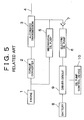
- Fig. 5 is an exemplary diagram showing how an electric oil pump is arranged in relation to the other component members of a so-called economy-running vehicle according to the related art.
- An output torque of an engine 1 is input to an automatic transmission 3 via a torque converter 2 and output to an output shaft 4 of the vehicle.
- An electric oil pump 6 is disposed in parallel with a mechanical oil pump 5 driven by the engine 1.
- An output from the electric oil pump 6 is coupled with an output from the mechanical oil pump 5 via a check valve 7 and then transmitted to the automatic transmission 3.
- the electric oil pump 6 is supplied with electric power from a battery 8 via a driver circuit 9, which is connected to an oil pump control device 10.
- the oil pump control device 10 transmits a drive signal for controlling an operation of the electric oil pump 6 to the driver circuit 9, and electric power in the battery 8 is then supplied to the electric oil pump 6 via the driver circuit 9, whereby the electric oil pump 6 is operated and generates a hydraulic pressure.
- This hydraulic pressure is transmitted through the hydraulic circuit via the check valve 7, suitably controlled by the hydraulic pressure control device (not shown), and supplied to the automatic transmission 3.
- the check valve 7 prevents a high hydraulic pressure in the mechanical oil pump 5 from being transmitted reversely to the electric oil pump 6.
- the electric oil pump 6 As described hereto, it is not the mechanical oil pump 5 but the electric oil pump 6 that operates when the engine 1 is out of operation.
- the electric oil pump 6 thus ensures a hydraulic pressure for operating the change-gear mechanism and the friction coupling element. As a result, the engine 1 can be restarted appropriately.
- the electric oil pump is in operation when the mechanical oil pump is out of operation during stoppage of the engine.
- the electric oil pump generates a hydraulic pressure which ensures operation of the friction coupling element and the change-gear mechanism, whereby the engine can be restarted appropriately.
- the hydraulic pressure output from the electric oil pump must be set much higher than an optimal output hydraulic pressure, in consideration of differences or aging-based changes in the performance of a motor for driving the electric oil pump, the output voltage of the driver circuit, the clearance of valves disposed in the automatic transmission or the hydraulic pressure controller thereof, and the like. For this reason, problems such as a shortened period of endurance of the motor and a deterioration in fuel consumption resulting from an increase in power consumption in an economy-running state are caused.
- a solution to these problems requires controlling the output hydraulic pressure on the basis of a result obtained by monitoring the optimal output hydraulic pressure.
- the invention thus provides an oil pump control device for an automatic transmission which offers an adequate solution to the problems caused in the control device for the electric oil pump according to the related art and which ensures an optimal hydraulic pressure output from the electric oil pump from the standpoint of operating a friction coupling element and a change-gear mechanism.
- an oil pump control device for an automatic transmission comprises an electric oil pump that is electrically driven to supply the automatic transmission with a hydraulic pressure, and a controller that updates the hydraulic pressure generated by the electric oil pump on the basis of kinetic characteristics of a torque transmission system during a start of an engine that is stopped automatically upon fulfillment of one of a predetermined number of running conditions of a vehicle and optimizing a hydraulic pressure supplied to the automatic transmission during a restart of the engine.
- a control method of the oil pump control device comprises the steps of setting a driving pattern of a motor for an electric oil pump that supplies a hydraulic pressure to an automatic transmission, measuring an input speed of the automatic transmission, and correcting the driving pattern on the basis of the input speed and a hydraulic pressure in the electric oil pump.
- the hydraulic pressure supplied to the automatic transmission can be optimized by updating the hydraulic pressure control characteristics of the electric oil pump on the basis of the kinetic characteristics of the engine torque transmission system and performing learning control of the hydraulic pressure control characteristics.
- the invention succeeds in ensuring that an optimal hydraulic pressure is output from the electric oil pump from the standpoint of operation of the friction coupling element and the change-gear mechanism.
- the invention is based on the discovery that the hydraulic pressure supplied to an axle clutch designed as a friction coupling portion in an automatic transmission and the turbine speed during restart of an engine are closely related to each other. First of all, it will be described how the hydraulic pressure supplied to the axle clutch and the turbine speed during restart of the engine are related to each other. It is to be noted herein that the turbine speed means the output speed of a torque converter, that is, the input speed of the automatic transmission.
- Fig. 1 is a schematic view of an engine torque transmission system extending from an engine to an output shaft of a vehicle according to an exemplary embodiment of the invention while the engine is being restarted.
- An automatic transmission 3, shown in Fig. 1 includes an axle clutch 11, that is, a forward clutch or a backward clutch designed as a friction coupling portion.
- An electric oil pump 6 supplies a hydraulic pressure to the axle clutch 11. This hydraulic pressure is suitably controlled by a hydraulic pressure controller (not shown).
- a turbine speed monitor 13 for monitoring a turbine speed NT or an input speed of the automatic transmission 3 is provided.
- the turbine speed monitor 13 is coupled to an oil pump controller 10 designed as a controller.
- An engine speed monitor 12 for monitoring an engine speed NE or an output from an engine 1 is also provided. It is assumed herein that the oil pump control device is composed of the automatic transmission 3, the electric oil pump 6, and the oil pump controller 10.
- the axle clutch 11 designed as a friction coupling portion securely couples the input shaft and the output shaft in the automatic transmission 3 by a frictional force. Because the output shaft 4 of the vehicle is at rest, the input shaft of the automatic transmission 3, securely coupled to the output shaft 4 of the vehicle by a frictional force, also does not rotate. Even if the engine 1 runs, it undergoes a slip in the torque converter 2. For this reason, the turbine speed NT or the input speed of the automatic transmission 3 is zero in this case.
- the axle clutch 11 designed as the friction coupling portion, is unable to securely couple the input shaft and the output shaft in the automatic transmission 3 by a frictional force. A slip is then caused between the input shaft and the output shaft in the axle clutch 11. Accordingly, the turbine speed NT or the input shaft of the automatic transmission 3 indicates a speed reflecting the effect of the slip even if the output shaft 4 of the vehicle is at rest.
- the hydraulic pressure in the electric oil pump 6 can thus be optimized by being controlled on the basis of a result obtained by monitoring the turbine speed NT.
- the optimal value of the hydraulic pressure supplied from the electric oil pump 6 will now be defined explicitly.
- the optimal value of the hydraulic pressure may be defined as being equal to or higher than a value that is obtained by gradually raising the hydraulic pressure until a slip is no longer caused in the axle clutch 11.
- the hydraulic pressure at the time when the slip ceases to be caused is extraordinarily high and threatens to cause a problem such as a shortened period of endurance of the electric oil pump 6.
- the optimal value of the hydraulic pressure is defined herein as being equal to or higher than a hydraulic pressure allowing a slip of such an amount that the driveability of the vehicle remains unaffected. That is to say, the optimal value of the hydraulic pressure is a threshold, which is a turning point of the susceptibility of the driveability to a slip.
- the turbine speed corresponding to the threshold (hereinafter referred to as the threshold turbine speed) is monitored.
- the hydraulic pressure can be optimized by being controlled on the basis of a result thus obtained by monitoring the threshold turbine speed.
- Fig. 2 is a graph showing a relation between turbine speed NT and hydraulic pressure.
- the hydraulic pressure supplied from the electric oil pump 6 is equal to the threshold hydraulic pressure.
- a suitable state in which the turbine speed NT is equal to the threshold turbine speed is defined as a state C. If the hydraulic pressure supplied from the electric oil pump 6 is equal to or lower than the threshold hydraulic pressure, the hydraulic pressure supplied to the axle clutch 11 is not sufficiently high. As a result, a slip of such an amount as to cause a problem regarding the driveability of the vehicle occurs, so that the turbine speed NT assumes a value higher than the threshold turbine speed.
- This state in which an extraordinary amount of slip is caused is defined as a state A. To make a shift from the state A to the suitable state C, it is appropriate that the hydraulic pressure supplied from the electric oil pump 6 be raised until the threshold turbine speed is reached while the turbine speed NT is being monitored.
- the axle clutch 11 is supplied with a hydraulic pressure that is quite sufficient. From the standpoint of the driveability of the vehicle, this hydraulic pressure unnecessarily inhibits a slip from being caused. Accordingly, no slip is caused at all in the case where a still higher hydraulic pressure is supplied. At this moment the turbine speed NT assumes a value lower than the threshold turbine speed. If the hydraulic pressure is extraordinarily high, the turbine speed NT is zero. This state in which the hydraulic pressure is extraordinarily high is defined as a state B. To make a shift from the state B to the suitable state C, it is appropriate that the hydraulic pressure supplied from the electric oil pump 6 be lowered until the threshold turbine speed is reached while the turbine speed NT is being monitored.
- the hydraulic pressure supplied to the automatic transmission 3 can thus be optimized by being controlled on the basis of a result obtained by monitoring kinetic characteristics of the engine torque transmission system extending from the engine to the output shaft of the vehicle during restart of the engine, for example, by monitoring the turbine speed NT or the input speed of the automatic transmission 3.
- Figs. 3a and 3b show processes in which the oil pump control device of the automatic transmission according to the exemplary embodiment of the invention optimizes the hydraulic pressure.
- the axis of abscissa represents time
- the axis of ordinate represents a hydraulic pressure 21 output from the electric oil pump according to the related art
- a hydraulic pressure 22 (22a-22c) output from the electric oil pump 6 a turbine speed 23 (23a-23c), and an engine speed 24 (24a-24b).
- FIG. 3a sequentially indicates the state A in which the engine 1 is running normally after having been started, the state B in which the engine 1 is out of operation, and the state C in which the engine 1 has been restarted prior to completion of the starting process thereof. Optimization of the hydraulic pressure is updated every time the engine 1 is restarted.
- the description will now be made in a time-series manner from the left along the time axis shown in Fig. 3a.
- the Roman numeral of each reference symbol of IA to IIIC in Fig. 3a denotes how many times the engine 1 has been operated. That is, the normal running state of the engine 1 after completion of the first starting process thereof is denoted by (IA).
- the hydraulic pressure output from the electric oil pump 6 is related to the speed of a DC motor for driving the pump.
- the hydraulic pressure output from the electric oil pump 6 can thus be set by determining a voltage output from a driver circuit 9 for supplying the DC motor with electric power from a battery 8.
- the effective voltage supplied to the DC motor can be set, for example, by converting a DC voltage output from the battery 8 into pulses by means of a chopper and setting a duty ratio of the pulses appropriately.
- the drive duty ratio of the electric oil pump 6 is thus set in the state (IB).
- the electric oil pump 6 is operated and generates a hydraulic pressure 22a corresponding to the drive duty ratio that has been set.
- the engine 1 is in the economy-running state at this moment.
- Fig. 3b a partially enlarged view of Fig. 3a shows how a turbine speed 23a and an engine speed 24a change in this state (IC).
- the state (IC) represents a transitional period in which the engine speed 24a rises after restart of the engine 1 and settles to a sufficiently stable speed. In this period as well, the electric oil pump 6 is in operation.
- the turbine speed 23a is measured when the engine 1 is in this state (IC). At this moment it is necessary to confirm that a throttle is fully closed in the transitional period.
- the necessity for such confirmation results from the fact that monitoring the turbine speed NT alone may lead to an erroneous determination on an amount of slip of the axle clutch 11 due to a torsion occurring in a drive system when the throttle is open.
- the turbine speed 24a is measured throughout the period in which the engine 1 is in the state (IC).
- a maximum or central value of the turbine speed 24a can be regarded as a turbine speed corresponding to the hydraulic pressure 22a of the electric oil pump 6.
- the electric oil pump 6 operates at the drive duty ratio updated in the state (IIA) and generates a hydraulic pressure 22b. If the engine 1 is then restarted for the second time, the turbine speed NT is measured again while the engine 1 is in the state (IIC). If the restarting process of the engine 1 is then completed for the second time, the electric oil pump 6 is stopped again.
- This state is defined as a third-time state (IIIA). When the engine 1 is in the third-time state (IIIA), the turbine speed NT measured when the engine 1 is in the second-time state (IIC) is compared with the threshold turbine speed. The drive duty ratio is then updated by still another value.
- the turbine speed NT during a certain process of restarting the engine 1 is measured and compared with the threshold turbine speed, and the drive duty ratio of the electric oil pump 6 is updated.
- another hydraulic pressure can be generated on the basis of the updated drive duty ratio.
- Fig. 3a shows, as a reference, the hydraulic pressure 21 output from the electric oil pump 6 according to the related art in which learning control is not performed. As is apparent from Fig. 3a, the hydraulic pressure 21 remains at an extraordinarily high constant value no matter when the engine 1 is restarted.
- Fig. 4 is a flowchart of procedures of updating the condition for driving the electric oil pump 6. These procedures are the most essential among a series of control procedures of optimizing the hydraulic pressure in the oil pump control device in the automatic transmission 3 according to the exemplary embodiment of the invention described with reference to Figs. 3a and 3b.
- STEP 1 represents a procedure of setting the condition for driving the electric oil pump 6.
- the drive duty ratio of the electric oil pump 6 is set, for example, by reference to a relation between the generated hydraulic pressure and the drive duty ratio of the electric motor for driving the electric oil pump 6.
- STEP 2 represents a procedure of measuring the turbine speed NT or the input speed of the automatic transmission 3. Because the vehicle is generally equipped with the turbine speed monitor 13, it is possible to make use of an output from the turbine speed monitor 13, whereby the necessity of providing the vehicle with an additional sensing portion is eliminated.
- the turbine speed NT is measured for a period which starts when the engine 1 in the economy-running state starts running in response to the issuance of a signal for restarting the engine 1 and which ends when the engine speed settles to a sufficiently stable value.
- the throttle must be fully closed to prevent an erroneous determination on an amount of slip of the axle clutch 11.
- STEP 3 represents a procedure of calculating a correction amount for the hydraulic pressure in respect of the turbine speed NT obtained in STEP 2 on the basis of the relation between the turbine speed NT and hydraulic pressure shown in Fig. 2 and calculating a correction amount for the drive duty ratio of the electric oil pump 6 which is necessitated to generate the corrected hydraulic pressure.
- the turbine speed NT or the input speed of the automatic transmission 3 during restart of the engine 1 is handled as the kinetic characteristics representative of the coupling characteristics of the axle clutch 11 acting as a friction coupling element.
- the invention can also be implemented by adopting other kinetic characteristics of the engine torque transmission system extending from the engine to the output shaft 4 of the vehicle during restart of the engine 1, such as acceleration of the output shaft 4, as long as adoption of the kinetic characteristics makes it possible to confirm whether a shock occurring in the change-gear mechanism during the coupling of the friction coupling element such as the axle clutch 11 causes a problem in terms of the driveability of the vehicle.
- learning control of the electric oil pump 6 has been described as a method of updating the drive duty ratio as a determinant of the effective voltage supplied to the DC motor for driving the electric oil pump 6, the invention can also be implemented by other generally employed methods of changing voltage and current.
- optimization of the hydraulic pressure supplied to the automatic transmission can also be construed as optimization through a learning control of the hydraulic pressure based on differences or aging-based changes in the performance of the motor for driving the electric oil pump, the output voltage of the driver circuit, the clearance of valves disposed in the automatic transmission or the hydraulic pressure controller thereof, and the like. Accordingly, the invention can be implemented, for example, by changing the hydraulic pressure control characteristics on the basis of fluctuant factors affecting the hydraulic pressure such as aging of the electric oil pump.
- the oil pump control device for the automatic transmission is designed to update the hydraulic pressure control characteristics of the electric oil pump on the basis of the kinetic characteristics of the engine torque transmission system extending from the engine to the output shaft of the vehicle during restart of the engine and to thereby optimize the hydraulic pressure supplied to the automatic transmission.
- the kinetic characteristics of the engine torque transmission system be defined as the input speed of the automatic transmission.
- the kinetic characteristics captured during restart of the engine in a certain period be used to update the hydraulic pressure control characteristics when the engine is restarted next time. It is to be noted herein that the input speed of the automatic transmission or the like depends on the coupling characteristics of the friction coupling element during restart of the engine and that the coupling characteristics are determined by the hydraulic pressure supplied to the automatic transmission.
- the hydraulic pressure supplied to the automatic transmission can thus be optimized by updating the hydraulic pressure control characteristics of the electric oil pump on the basis of the kinetic characteristics of the engine torque transmission system and performing learning control of the hydraulic pressure control characteristics.
- the invention succeeds in ensuring that an optimal hydraulic pressure is output from the electric oil pump from the standpoint of operation of the friction coupling element and the change-gear mechanism.
- the controllers e.g., the oil pump controller 10 and the hydraulic pressure controller
- the controllers are implemented as one or more programmed general purpose computers. It will be appreciated by those skilled in the art that the controllers can be implemented using a single special purpose integrated circuit (e.g., ASIC) having a main or central processor section for overall, system-level control, and separate sections dedicated to performing various different specific computations, functions and other processes under control of the central processor section.
- the controllers can be a plurality of separate dedicated or programmable integrated or other electronic circuits or devices (e.g., hardwired electronic or logic circuits such as discrete element circuits, or programmable logic devices such as PLDs, PLAs, PALs or the like).
- the controllers can be implemented using a suitably programmed general purpose computer, e.g., a microprocessor, microcontroller or other processor device (CPU or MPU), either alone or in conjunction with one or more peripheral (e.g., integrated circuit) data and signal processing devices.
- a suitably programmed general purpose computer e.g., a microprocessor, microcontroller or other processor device (CPU or MPU)
- CPU or MPU processor device
- peripheral e.g., integrated circuit
- any device or assembly of devices on which a finite state machine capable of implementing the procedures described herein can be used as the controller.
- a distributed processing architecture can be used for maximum data/signal processing capability and speed.
- a condition for driving an electric oil pump (6) is set.
- a turbine speed (NT) or an input speed of an automatic transmission (3) is measured.
- a correction amount for a hydraulic pressure is calculated on the basis of the turbine speed obtained by reference to a relation between the turbine speed (NT) and hydraulic pressure, and a correction amount for a drive duty ratio of the electric oil pump (6) which is required for generation of the corrected hydraulic pressure is calculated.
- the procedure is resumed after the procedure has been performed.
- the condition for driving the electric oil pump (6) is updated on the basis of the correction amount for the drive duty ratio calculated.
Landscapes
- Engineering & Computer Science (AREA)
- General Engineering & Computer Science (AREA)
- Mechanical Engineering (AREA)
- Control Of Transmission Device (AREA)
- Output Control And Ontrol Of Special Type Engine (AREA)
- Control Of Vehicle Engines Or Engines For Specific Uses (AREA)
- General Details Of Gearings (AREA)
Applications Claiming Priority (2)
| Application Number | Priority Date | Filing Date | Title |
|---|---|---|---|
| JP2001180657A JP3925111B2 (ja) | 2001-06-14 | 2001-06-14 | 自動変速機のオイルポンプ制御装置 |
| JP2001180657 | 2001-06-14 |
Publications (3)
| Publication Number | Publication Date |
|---|---|
| EP1267100A2 true EP1267100A2 (de) | 2002-12-18 |
| EP1267100A3 EP1267100A3 (de) | 2006-10-25 |
| EP1267100B1 EP1267100B1 (de) | 2009-01-21 |
Family
ID=19021041
Family Applications (1)
| Application Number | Title | Priority Date | Filing Date |
|---|---|---|---|
| EP02012996A Expired - Lifetime EP1267100B1 (de) | 2001-06-14 | 2002-06-12 | Vorrichtung und Verfahren zur Steuerung einer Ölpumpe in einem Automatikgetriebe |
Country Status (4)
| Country | Link |
|---|---|
| US (1) | US6716138B2 (de) |
| EP (1) | EP1267100B1 (de) |
| JP (1) | JP3925111B2 (de) |
| DE (1) | DE60230952D1 (de) |
Families Citing this family (18)
| Publication number | Priority date | Publication date | Assignee | Title |
|---|---|---|---|---|
| JP3842150B2 (ja) * | 2002-03-08 | 2006-11-08 | 本田技研工業株式会社 | 車両制御装置 |
| JP3574121B2 (ja) * | 2002-08-07 | 2004-10-06 | 本田技研工業株式会社 | ハイブリッド車両のエンジン停止始動制御装置 |
| CN1301200C (zh) * | 2002-09-13 | 2007-02-21 | 本田技研工业株式会社 | 混合车辆 |
| JP2005098468A (ja) * | 2003-09-26 | 2005-04-14 | Koyo Seiko Co Ltd | 車載用電動モータの運転方法 |
| JP5396319B2 (ja) * | 2010-03-23 | 2014-01-22 | 日立オートモティブシステムズ株式会社 | 自動変速機の油圧供給装置 |
| JP5054800B2 (ja) | 2010-05-10 | 2012-10-24 | 三菱電機株式会社 | 自動変速機の制御装置 |
| JP5396374B2 (ja) * | 2010-11-26 | 2014-01-22 | ジヤトコ株式会社 | 車両の制御装置 |
| KR101231327B1 (ko) * | 2010-11-30 | 2013-02-07 | 기아자동차주식회사 | 자동변속기 아이에스지 차량의 전동식 오일펌프 제어방법 |
| KR20140002730A (ko) | 2011-02-09 | 2014-01-08 | 알리손 트랜스미션, 인크. | 스캐빈지 펌프 오일 레벨 제어 시스템 및 방법 |
| CA2827626C (en) | 2011-02-17 | 2018-05-15 | Allison Transmission, Inc. | Modulation control system and method for a hybrid transmission |
| WO2012125337A2 (en) | 2011-03-11 | 2012-09-20 | Allison Transmission, Inc. | Clogged filter detection system and method |
| AU2012273001B2 (en) | 2011-06-22 | 2015-04-23 | Allison Transmission, Inc. | Low level oil detection system and method |
| JP5585736B2 (ja) * | 2011-10-17 | 2014-09-10 | トヨタ自動車株式会社 | 車両制御装置 |
| WO2013093986A1 (ja) * | 2011-12-24 | 2013-06-27 | 川崎重工業株式会社 | 電動車両 |
| KR101326850B1 (ko) * | 2012-10-04 | 2013-11-11 | 기아자동차주식회사 | 오일펌프 제어 시스템 및 방법 |
| AU2013338541B2 (en) | 2012-10-31 | 2016-04-28 | Allison Transmission, Inc. | Method of controlling a hydraulic pressurization system of a transmission |
| KR101860080B1 (ko) * | 2012-12-17 | 2018-05-21 | 콘티넨탈 오토모티브 시스템 주식회사 | Isg 차량의 업 쉬프트시 유압 학습 방법 및 장치 |
| CN114962623B (zh) * | 2022-05-17 | 2023-09-15 | 上汽通用五菱汽车股份有限公司 | 车辆起步控制的方法、装置、计算机设备和可读存储介质 |
Family Cites Families (20)
| Publication number | Priority date | Publication date | Assignee | Title |
|---|---|---|---|---|
| JP2738202B2 (ja) | 1992-03-18 | 1998-04-08 | 三菱自動車工業株式会社 | 車両用自動変速機の変速制御方法 |
| JP3055346B2 (ja) | 1993-03-08 | 2000-06-26 | 日産自動車株式会社 | 自動変速機のセレクトショック軽減装置 |
| JP3463361B2 (ja) | 1994-04-28 | 2003-11-05 | 株式会社デンソー | エンジン自動停止始動装置 |
| JPH084888A (ja) | 1994-06-22 | 1996-01-12 | Nippondenso Co Ltd | 自動変速機の制御装置 |
| JP3773977B2 (ja) | 1995-01-18 | 2006-05-10 | 三菱自動車工業株式会社 | 自動変速機の変速制御装置 |
| JP3011069B2 (ja) | 1995-09-07 | 2000-02-21 | トヨタ自動車株式会社 | 車両の制御装置 |
| JP3861340B2 (ja) * | 1996-09-11 | 2006-12-20 | アイシン・エィ・ダブリュ株式会社 | 車両用動力伝達装置の電動オイルポンプ制御装置 |
| JP3629890B2 (ja) | 1997-05-22 | 2005-03-16 | 日産自動車株式会社 | ハイブリッドシステム車両の発進装置 |
| JPH11107798A (ja) * | 1997-10-08 | 1999-04-20 | Aisin Aw Co Ltd | ハイブリッド駆動装置 |
| JP3518406B2 (ja) | 1998-05-15 | 2004-04-12 | トヨタ自動車株式会社 | 車両のエンジン再始動時の制御装置 |
| JP2000046165A (ja) * | 1998-07-30 | 2000-02-18 | Toyota Motor Corp | 車両用駆動装置の制御装置 |
| JP3840829B2 (ja) * | 1998-09-14 | 2006-11-01 | トヨタ自動車株式会社 | 車両のエンジン再始動時の制御装置 |
| JP4055297B2 (ja) * | 1998-12-11 | 2008-03-05 | トヨタ自動車株式会社 | 伝動装置用電動オイルポンプを備えた車両の制御装置 |
| JP3827926B2 (ja) * | 1999-07-29 | 2006-09-27 | 本田技研工業株式会社 | エンジン自動停止車両の自動変速機用油圧回路及び油圧制御装置 |
| JP2001065675A (ja) * | 1999-08-26 | 2001-03-16 | Honda Motor Co Ltd | 車両制御装置 |
| JP4064016B2 (ja) * | 1999-09-13 | 2008-03-19 | 本田技研工業株式会社 | 内燃機関の始動制御装置 |
| JP4066589B2 (ja) * | 2000-03-06 | 2008-03-26 | トヨタ自動車株式会社 | 内燃機関のアイドリングストップ制御装置およびこれを備える車両 |
| JP3562432B2 (ja) * | 2000-04-12 | 2004-09-08 | 日産自動車株式会社 | 車両のエンジン自動停止再始動装置 |
| JP4066616B2 (ja) * | 2000-08-02 | 2008-03-26 | トヨタ自動車株式会社 | 内燃機関の自動始動制御装置及び動力伝達状態検出装置 |
| JP3975693B2 (ja) * | 2001-06-14 | 2007-09-12 | トヨタ自動車株式会社 | エンジン自動停止/再始動車両 |
-
2001
- 2001-06-14 JP JP2001180657A patent/JP3925111B2/ja not_active Expired - Lifetime
-
2002
- 2002-05-30 US US10/156,938 patent/US6716138B2/en not_active Expired - Lifetime
- 2002-06-12 EP EP02012996A patent/EP1267100B1/de not_active Expired - Lifetime
- 2002-06-12 DE DE60230952T patent/DE60230952D1/de not_active Expired - Lifetime
Also Published As
| Publication number | Publication date |
|---|---|
| DE60230952D1 (de) | 2009-03-12 |
| EP1267100B1 (de) | 2009-01-21 |
| EP1267100A3 (de) | 2006-10-25 |
| JP3925111B2 (ja) | 2007-06-06 |
| JP2002372135A (ja) | 2002-12-26 |
| US6716138B2 (en) | 2004-04-06 |
| US20020193206A1 (en) | 2002-12-19 |
Similar Documents
| Publication | Publication Date | Title |
|---|---|---|
| US6716138B2 (en) | Oil pump control device for automatic transmission and control method of the same | |
| US9039383B2 (en) | Control apparatus for electric oil pump | |
| US5216938A (en) | Control apparatus with fail-safe faculty | |
| US20060172829A1 (en) | Method of controlling continuously variable transmission and control system | |
| CN113027628B (zh) | 车辆控制装置 | |
| US6760655B2 (en) | Automatic engine stop/restart-type vehicle, method of controlling the same, and automatic engine stop apparatus | |
| US6637566B2 (en) | Lock-up control device for torque converter of automatic transmission | |
| US7058497B2 (en) | Apparatus and method for determining a failure in an automatic transmission | |
| CN1296688C (zh) | 确定自动变速器故障的装置和方法 | |
| KR100838119B1 (ko) | 차량용 자동 변속기의 편차 보정방법 | |
| JP3298480B2 (ja) | トルクコンバータのロックアップ制御装置 | |
| KR101766017B1 (ko) | Eop 로터 마모진단 방법 | |
| KR20200071180A (ko) | 하이브리드 차량의 윤활조절밸브 고착 진단 방법 | |
| JP3183240B2 (ja) | トルクコンバータのロックアップ制御装置 | |
| JP2005291174A (ja) | 車両用エンジンのトルク制御装置 | |
| JP2021080945A (ja) | 自動変速機の制御装置 | |
| US7144350B2 (en) | Method and device for monitoring the errors of an electronic control unit of an automated transmission that is situated in the drive train of a motor vehicle | |
| KR100427288B1 (ko) | 댐퍼 클러치 고장 진단방법 | |
| EP1643164A2 (de) | Fehlerdetektor für Drehmesswertgeber | |
| CN110701266B (zh) | 动力传递装置的控制装置 | |
| US12583439B2 (en) | Systems and methods for predicting a disconnect clutch time to connection | |
| US20220316589A1 (en) | Control method and control device for vehicular automatic transmission and recording medium | |
| JP2002349701A (ja) | シフトバイワイヤシステム | |
| JP4175305B2 (ja) | 自動変速機の変速過渡制御装置 | |
| JP2973208B2 (ja) | 自動変速機の油圧制御装置 |
Legal Events
| Date | Code | Title | Description |
|---|---|---|---|
| PUAI | Public reference made under article 153(3) epc to a published international application that has entered the european phase |
Free format text: ORIGINAL CODE: 0009012 |
|
| 17P | Request for examination filed |
Effective date: 20020612 |
|
| AK | Designated contracting states |
Kind code of ref document: A2 Designated state(s): AT BE CH CY DE DK ES FI FR GB GR IE IT LI LU MC NL PT SE TR |
|
| AX | Request for extension of the european patent |
Free format text: AL;LT;LV;MK;RO;SI |
|
| PUAL | Search report despatched |
Free format text: ORIGINAL CODE: 0009013 |
|
| AK | Designated contracting states |
Kind code of ref document: A3 Designated state(s): AT BE CH CY DE DK ES FI FR GB GR IE IT LI LU MC NL PT SE TR |
|
| AX | Request for extension of the european patent |
Extension state: AL LT LV MK RO SI |
|
| 17Q | First examination report despatched |
Effective date: 20061221 |
|
| AKX | Designation fees paid |
Designated state(s): DE FR |
|
| GRAP | Despatch of communication of intention to grant a patent |
Free format text: ORIGINAL CODE: EPIDOSNIGR1 |
|
| GRAS | Grant fee paid |
Free format text: ORIGINAL CODE: EPIDOSNIGR3 |
|
| GRAA | (expected) grant |
Free format text: ORIGINAL CODE: 0009210 |
|
| AK | Designated contracting states |
Kind code of ref document: B1 Designated state(s): DE FR |
|
| REF | Corresponds to: |
Ref document number: 60230952 Country of ref document: DE Date of ref document: 20090312 Kind code of ref document: P |
|
| PLBE | No opposition filed within time limit |
Free format text: ORIGINAL CODE: 0009261 |
|
| STAA | Information on the status of an ep patent application or granted ep patent |
Free format text: STATUS: NO OPPOSITION FILED WITHIN TIME LIMIT |
|
| 26N | No opposition filed |
Effective date: 20091022 |
|
| REG | Reference to a national code |
Ref country code: FR Ref legal event code: PLFP Year of fee payment: 15 |
|
| REG | Reference to a national code |
Ref country code: FR Ref legal event code: PLFP Year of fee payment: 16 |
|
| REG | Reference to a national code |
Ref country code: FR Ref legal event code: PLFP Year of fee payment: 17 |
|
| PGFP | Annual fee paid to national office [announced via postgrant information from national office to epo] |
Ref country code: DE Payment date: 20210518 Year of fee payment: 20 Ref country code: FR Payment date: 20210513 Year of fee payment: 20 |
|
| REG | Reference to a national code |
Ref country code: DE Ref legal event code: R071 Ref document number: 60230952 Country of ref document: DE |