EP1267158A2 - Verfahren zur Untersuchung äusserlich vorgespannter ummantelter Kabel - Google Patents
Verfahren zur Untersuchung äusserlich vorgespannter ummantelter Kabel Download PDFInfo
- Publication number
- EP1267158A2 EP1267158A2 EP02291439A EP02291439A EP1267158A2 EP 1267158 A2 EP1267158 A2 EP 1267158A2 EP 02291439 A EP02291439 A EP 02291439A EP 02291439 A EP02291439 A EP 02291439A EP 1267158 A2 EP1267158 A2 EP 1267158A2
- Authority
- EP
- European Patent Office
- Prior art keywords
- electrodes
- sheath
- frequency
- oscillator circuit
- grout
- Prior art date
- Legal status (The legal status is an assumption and is not a legal conclusion. Google has not performed a legal analysis and makes no representation as to the accuracy of the status listed.)
- Withdrawn
Links
Images





Classifications
-
- G—PHYSICS
- G01—MEASURING; TESTING
- G01N—INVESTIGATING OR ANALYSING MATERIALS BY DETERMINING THEIR CHEMICAL OR PHYSICAL PROPERTIES
- G01N27/00—Investigating or analysing materials by the use of electric, electrochemical, or magnetic means
- G01N27/02—Investigating or analysing materials by the use of electric, electrochemical, or magnetic means by investigating impedance
- G01N27/22—Investigating or analysing materials by the use of electric, electrochemical, or magnetic means by investigating impedance by investigating capacitance
- G01N27/24—Investigating the presence of flaws
-
- G—PHYSICS
- G01—MEASURING; TESTING
- G01N—INVESTIGATING OR ANALYSING MATERIALS BY DETERMINING THEIR CHEMICAL OR PHYSICAL PROPERTIES
- G01N27/00—Investigating or analysing materials by the use of electric, electrochemical, or magnetic means
- G01N27/02—Investigating or analysing materials by the use of electric, electrochemical, or magnetic means by investigating impedance
- G01N27/22—Investigating or analysing materials by the use of electric, electrochemical, or magnetic means by investigating impedance by investigating capacitance
- G01N27/221—Investigating or analysing materials by the use of electric, electrochemical, or magnetic means by investigating impedance by investigating capacitance by investigating the dielectric properties
Definitions
- the invention relates to a non-destructive diagnostic method. prestressing reinforcement cables contained in sheaths (or insulating ducts arranged outside of concrete structures and in which the residual space between the reinforcing cables and the inner wall of the sheath contains a grout based on hydraulic binder.
- the cables are arranged inside sheaths, generally HDPE. To ensure the durability of the cables, we generally inject in the residual space between the cable and the inner face of the sheath a grout based on hydraulic binder.
- Cable breaks have recently occurred on some works. After examinations and investigations, it appears that these breaks occurred by oxidation of cables, in areas where the cable is poorly protected or is not protected by grout. This can be produce by the absence of grout in certain areas, the presence of air pockets, the presence of water with or without a whitish product at the grout surface. It should be noted that the cable tension is 0.8 times the guaranteed breaking force. The presence of oxidation can cause the rupture of a strand, then in cascade the rupture of a strand or even of the cable.
- a device for measuring the water content of granular or powdery materials, especially moving materials on a conveyor belt or in a pipe which includes a capacitive probe with at least two electrodes separated by an insulating zone and in contact with the material to study, and a high frequency oscillator associated with the electrodes so to provide an alternating voltage of variable frequency with the content of water.
- This measuring device in the form of a cylinder or warhead is fixed and is disposed in the moving material.
- FR 2 703 462 relates to another arrangement of a continuous measurement of the water content of a powdery granular material or fibrous.
- the electrodes arranged at a certain distance from each other on an insulating support are also placed on the path of the material where the material is conditioned by the support.
- US 4,240,028 describes an apparatus for measuring the degree of water saturation in an oil circulating in a non-conductive pipe.
- This device has electrodes attached to the hose, which deliver signals whose frequency is a function of the water-oil mixture. These signals are mixed with reference signals provided by a second oscillator and whose calibrated frequency corresponds to that of water without oil circulating in the pipe, the difference between the two frequencies is transformed into an analog signal using a conventional technique.
- WO97 / 00453 also describes a method for measuring the percentages of two fluids including oil flowing in a non conductor by means of a plurality of electrodes fixed around the pipe. These electrodes are excited and auscultated in turn. It's the whole voltages recorded on all the electrodes excited one after the others which makes it possible to determine the distribution of the two fluids by a processing of values taking into account an assembly of capacities dielectric inter-electrodes in series-parallel.
- the idea which served as the basis for the invention is the fact that the disorders of the prestressed cables outside the concrete, enclosed in sheaths are mainly due to oxidation by presence of water in the grout, or the presence of air pockets capable of accommodating water, because the water rises in the grout by capillary action and causes the adjuvants.
- the material of the sheath is electrically insulating, it is not obvious that the capacity expressed in farad of a capacitor made up of two metallic electrodes applied to the external face of a portion of sheath containing a cable prestress embedded in a grout to detect anomalies such as the presence of air pockets or the presence of water due to in particular the presence of the metal cable in the sheath.
- test body comprising a sheath element closed at both ends by flanges transparent and containing a cable element, in which the flanges have holes for the introduction and emptying of different materials such as water and sand, have verified that it is possible to auscultate external prestress to concrete by a probe adapted capacitive.
- the diagnostic method is characterized by the fact that you are using a portable device with at least two electrodes in the form of separate cylindrical metal plates one on the other and capable of being applied against the external wall of said sheath and a high frequency oscillator circuit connected to said electrodes, operating at a frequency between 25 and 75 MHz, and likely to provide a variable frequency depending on the value of the capacitance of the capacitor formed by said electrodes and the environment of the latter, the said sheath is examined by successively applying said electrodes on portions of the external wall of said sheath and we analyze the frequency provided by the oscillator circuit during auscultation.
- the oscillator circuit includes a frequency which outputs a low frequency signal in the range of 5,000 or 40,000 Hz.
- the low frequency signal supplied is analyzed by a module processing electronics.
- a first analysis consists in making the difference between the frequency provided during an auscultation of a wall portion and a reference frequency provided when the electrodes are in the air.
- a second analysis consists in comparing the differences of frequency of the different auscultations of a section of sheath with the frequency differences of equivalent auscultations performed on a section of sheath deemed healthy.
- the invention also relates to a device for setting process work.
- the electrodes are mounted so removable and the electrode holder is made of a material sufficiently flexible to fit the outer wall of the sheath.
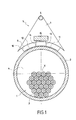
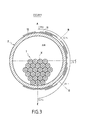
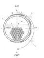
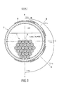
- Figures 2 and 3 show a prestressed cable 1 arranged in an insulating sheath 2 of axis X, itself disposed outside of a concrete structure.
- the sheath 2 is made for example of high-density polyethylene density, HDPE, and the cable 1 comprises a plurality of strands 3 of steel, for example 27 strands made of 7 steel wires.
- HDPE high-density polyethylene density
- Cable 1 occupies more than half of the internal volume of the sheath 2.
- the volume unoccupied by cable 1 is filled by injecting a grout 4 based on hydraulic binder which protects cable 1 against oxidation.
- the object of the invention is to propose a device 5 and a method for detecting the presence of air pockets or humidity in the grout 4.
- the device 5 includes a grip handle 6 connecting two insulating walls 7 and 8 of generally triangular shape, the edges 9 remote from the handle 6 are substantially circular.
- a support cylindrical 10, of insulating and flexible material is fixed on the circular edges 9 of the two walls 7 and 8.
- This cylindrical support 10 has on its concave external face two metal plates 11, 12 separated from each other and connected by conducting wires 13 and 14 to a high frequency oscillator circuit 15.
- the high frequency oscillator circuit 15 further includes a frequency divider 16 which outputs a low frequency function signal of the capacity expressed in farad of the capacitor constituted by the plates 13 and 14 and the external environment of these plates.
- the plates 13 and 14 thus play the role of capacitor electrodes.
- the low frequency signal is transmitted by cable 17 to a module signal processing electronics, not shown in the drawing and which includes a frequency meter.
- Reference 18 designates a circuit supply cable oscillator 15 and frequency divider 16 in DC 10 V for example.
- the cylindrical support 10 has two electrodes 11, 12, but it could also have a plurality of electrodes connected two by two, in particular an electrode central and two side electrodes electrically connected together.
- the oscillator circuit 15 at high frequency, as well as the frequency divider 16 are functionally similar to the electronic circuits described in FR 2 527 776 and do not need no further explanation.
- the high frequency oscillator circuit 15 and the divider of frequency are mounted on the insulating wall 9.
- the plates 11 and 12 forming electrodes are sufficiently thin so that they can follow the contour of the external surface of the sheath 2 when the cylindrical support 10 is applied against the sheath X.
- the radius of curvature of the concave external surface of the support 10 is substantially equal to the mean radius of the sheath 2 to be examined.
- the plates 11 and 12 measure for example 25 mm in the circumferential and 150 mm in the direction of the direction of the handle 6 and are preferably made of copper. They are spaced 10 mm.
- the device 5 further comprises a switch not shown on the drawing to supply on demand the oscillator circuit 15 and the divider of frequency 16 in electric current.
- the high frequency oscillator 15 operates at a frequency between 25 and 75 MHz, and the frequency divider 16 delivers a low frequency signal in the 5,000 Hz or 40,000 Hz range.
- working frequency and the frequency of the signal delivered are a function of relative dielectric constants of materials interposed between electrodes 11 and 12.
- the device 5 is energized for at least 15 mm and note the reference frequency F0 delivered by the divider of frequency 16, the electrodes 11 and 12 being in the air.
- the operator 6 presses electrodes 11 and 12 against the sheath 2.
- electrodes 11 and 12 against the sheath 2.
- the electronic processing module receives signals to low frequency for each auscultation. He subtracts from each measurement the reference frequency F0, taken at the start of the process and that it is possible to refresh from time to time. The difference in frequencies can be displayed at each auscultation by the frequency meter.
- the measurement obtained provides for the cross section considered (abscissa along the X axis) and the angle ⁇ of the surface portion examined with a vertical radial plane containing the X axis, an indication of the quality of the grout 4 in the vicinity of this surface portion.
- abscissa X and the angle ⁇ in question can be introduced into the electronic processing module, which allows the latter to store the data (abscissa, angle and measurement of the frequency difference) for subsequent automatic processing.
- the device 5 having been energized for approximately 15 min, we noted the reference frequency F0 delivered by the divider of frequency 16, the electrodes 11 and 12 being in the air, in order to control the temporal stability of the device 5. It has been observed that, during the series of the tests which lasted half a day, F0 varied only by 7 Hz.
- the electrodes 11 and 12 at several points on the upper generator of the sheath element filled with air and containing the cable element 2, noting the reference frequency F0. it was found that the differences are small, from 2 to 3 Hz. These deviations are mainly due to positioning and slightly different applied pressures.
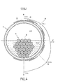
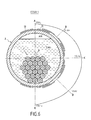
- test results are reported on the test sheets numbered from 1 to 9 shown in Figures 3 to 12 on which there are represented both the position of the electrodes, the level of the different materials filling the conduit, the values of the frequency differences ⁇ F between those measured on the test body and that of reference in the air F0.
- Frequency differences are indicated by a number corresponding to the average of the values of 3 to 4 measurements and represented by a segment of length proportional to their value carried by the axis of symmetry X of the electrodes 11, 12 at each point of measure numbered from 1 to 5. The ends of the segments have been connected by an envelope curve.
- test 9 where we have a combination of saturated sand, a layer of supernatant water (1.5 cm) and air pocket (1 cm), we detect less heterogeneity. In particular, it is difficult identify the air pocket.
- the electrodes 11, 12 used are of interest to a measurement volume too large to detect small air pockets. he it would probably suffice to modify the geometry of the electrodes 11, 12 so that the measurement volume is better suited to detecting small pockets.
- the plates 11 and 12 forming electrodes are spaced in the circumferential direction of the sheath to be examined, but they could also be placed on the same generators of the sheath to be examined without leaving the framework of the invention, and spaced in the axial direction of the sheath to be examined.
- the electronic signal processing module connected to the cable 17, may be a portable type microcomputer, which allows view on the screen in real time, the results of the measurements, and who records the frequency measurements on a disc.
- Device 5 can advantageously include a coding wheel which measures the distance traversed by the sensor along the sheath. How the sensor is controlled by the microcomputer equipped with an acquisition card on the PCMIA port and suitable software. Information from the encoder wheel are also saved to disk. We thus have continuous measurement along the sheath of the prestressing cable, to a determined angular position of the device 5 around the axis of the sheath.
- the measures can be used for the first time on site.
- the final use and interpretation of the measurements can be made later using a spreadsheet for example.
- the link between the device 5 and the microcomputer can be carried out advantageously by radio means without wire, in order to remove the cable 17. This may be useful to facilitate the work on a structure comprising sheaths of reinforcing cables prestressing, because access to these ducts is generally difficult.
Landscapes
- Chemical & Material Sciences (AREA)
- Chemical Kinetics & Catalysis (AREA)
- Electrochemistry (AREA)
- Physics & Mathematics (AREA)
- Health & Medical Sciences (AREA)
- Life Sciences & Earth Sciences (AREA)
- Analytical Chemistry (AREA)
- Biochemistry (AREA)
- General Health & Medical Sciences (AREA)
- General Physics & Mathematics (AREA)
- Immunology (AREA)
- Pathology (AREA)
- Investigating Or Analyzing Materials By The Use Of Electric Means (AREA)
Applications Claiming Priority (2)
| Application Number | Priority Date | Filing Date | Title |
|---|---|---|---|
| FR0107719A FR2826122B1 (fr) | 2001-06-13 | 2001-06-13 | Methode de diagnostic de cables de precontrainte externe contenus dans des gaines |
| FR0107719 | 2001-06-13 |
Publications (2)
| Publication Number | Publication Date |
|---|---|
| EP1267158A2 true EP1267158A2 (de) | 2002-12-18 |
| EP1267158A3 EP1267158A3 (de) | 2005-11-09 |
Family
ID=8864254
Family Applications (1)
| Application Number | Title | Priority Date | Filing Date |
|---|---|---|---|
| EP02291439A Withdrawn EP1267158A3 (de) | 2001-06-13 | 2002-06-11 | Verfahren zur Untersuchung äusserlich vorgespannter ummantelter Kabel |
Country Status (2)
| Country | Link |
|---|---|
| EP (1) | EP1267158A3 (de) |
| FR (1) | FR2826122B1 (de) |
Cited By (1)
| Publication number | Priority date | Publication date | Assignee | Title |
|---|---|---|---|---|
| FR3017462A1 (fr) * | 2014-02-12 | 2015-08-14 | Electricite De France | Procede de detection de defaut de soudure. |
Families Citing this family (1)
| Publication number | Priority date | Publication date | Assignee | Title |
|---|---|---|---|---|
| CN107102038B (zh) * | 2017-06-12 | 2023-04-11 | 重庆交通大学 | 基于等效串联电容测量的拉索锈蚀损伤检测系统及方法 |
Family Cites Families (3)
| Publication number | Priority date | Publication date | Assignee | Title |
|---|---|---|---|---|
| US4240028A (en) * | 1979-04-27 | 1980-12-16 | Texaco Inc. | Means and method for determining water saturation of oil |
| FR2527776A1 (fr) * | 1982-05-26 | 1983-12-02 | France Etat | Dispositif de mesure de la teneur en eau de materiaux granulaires |
| GB9512322D0 (en) * | 1995-06-16 | 1995-08-16 | Process Tomography Ltd | A flexible field excitation and measurement technique for electrical capacitance tomography systems |
-
2001
- 2001-06-13 FR FR0107719A patent/FR2826122B1/fr not_active Expired - Fee Related
-
2002
- 2002-06-11 EP EP02291439A patent/EP1267158A3/de not_active Withdrawn
Cited By (2)
| Publication number | Priority date | Publication date | Assignee | Title |
|---|---|---|---|---|
| FR3017462A1 (fr) * | 2014-02-12 | 2015-08-14 | Electricite De France | Procede de detection de defaut de soudure. |
| WO2015121591A1 (fr) * | 2014-02-12 | 2015-08-20 | Electricite De France | Procede de detection de defaut de soudure |
Also Published As
| Publication number | Publication date |
|---|---|
| EP1267158A3 (de) | 2005-11-09 |
| FR2826122A1 (fr) | 2002-12-20 |
| FR2826122B1 (fr) | 2004-01-23 |
Similar Documents
| Publication | Publication Date | Title |
|---|---|---|
| EP3574314B1 (de) | Verfahren zur steuerung einer flexiblen leitung und zugehörige steuerungsvorrichtung | |
| FR2692044A1 (fr) | Dispositif et procédé d'échantillonnage de tubes pour un diagnostic de défauts et de propriétés physiques de ces tubes et de leur environnement. | |
| EP2434280A2 (de) | Zerstörungsfreie Prüfung einer Struktur in einem Flugzeug | |
| CA2262273A1 (fr) | Dispositif et procede de mesure en continu de l'usure d'une paroi de recipient metallurgique | |
| EP0449753B1 (de) | Verfahren und Vorrichtung zur Kontrolle von metallischen Rohren unter Verwendung von Wirbelströmen | |
| WO1988004028A1 (fr) | Procede pour detecter des variations d'epaisseur dans la paroi d'un corps tubulaire conducteur de l'electricite | |
| FR2795521A1 (fr) | Procede et dispositif pour determiner la resistivite d'une formation traversee par un puits tube | |
| FR2666661A1 (fr) | Procede et dispositif de diagraphie pour mesurer la resistivite des formations geologiques. | |
| EP0030889B1 (de) | Verfahren und Vorrichtung zum zerstörungsfreien Prüfen von Punktschweissungen | |
| WO2019129806A1 (fr) | Embout de connexion d'une ligne flexible, procédé de fabrication et méthode de surveillance associés | |
| EP1155313B1 (de) | Verfahren und vorrichtung zur in-situ messung des abstandes zwischen zwei elementen in einer rohrleitung | |
| EP1267158A2 (de) | Verfahren zur Untersuchung äusserlich vorgespannter ummantelter Kabel | |
| FR2459476A1 (fr) | Procede et dispositif d'inspection de produits metalliques par courants de foucault | |
| EP3692352B1 (de) | Vorrichtung zur kontinuierlichen überwachung von defekten in einem rohrleitungsabschnitt sowie ein überwachungssystem mit mindestens zwei überwachungsvorrichtungen | |
| FR2804213A1 (fr) | Procede et dispositif de controle d'un cable de telecommunication | |
| FR3062481A1 (fr) | Dispositif et procede electromagnetique de detection de defauts | |
| JPH0666957A (ja) | 複合センサー付き積雪検層ゾンデ | |
| FR2827318A1 (fr) | Dispositif permettant d'evaluer la resistance mecanique d'un sol ou analogue | |
| EP0209476A2 (de) | Verfahren und Vorrichtung zur Feststellung des Auftretens und zur Quantifizierung der Entwicklung von Rissen auf der Oberfläche eines Materials | |
| EP3710816A1 (de) | Verfahren zur charakterisierung und überwachung der homogenität von durch lasersintern hergestellten metallteilen | |
| FR2834341A1 (fr) | Sonde controle, par courants de foucault, d'un materiau entourant un tube, procede de traitement des signaux fournis par la sonde, application aux echangeurs de chaleur | |
| EP0580485A1 (de) | System zur Kontrolle von Kanalisation insbesondere aus Stahl mit oder ohne Ummantelung | |
| FR2902191A1 (fr) | Dispositif de controle non destructif permettant de determiner la presence de materiau magnetique dans des materiaux non magnetiques ou a magnetisme oriente comme par exemple les soudures | |
| FR2982372A1 (fr) | Systeme et methode de controle d'un cable electrique | |
| WO2020201664A2 (fr) | Systeme utile pour evaluer l'endommagement d'une piece en materiau composite |
Legal Events
| Date | Code | Title | Description |
|---|---|---|---|
| PUAI | Public reference made under article 153(3) epc to a published international application that has entered the european phase |
Free format text: ORIGINAL CODE: 0009012 |
|
| AK | Designated contracting states |
Kind code of ref document: A2 Designated state(s): AT BE CH CY DE DK ES FI FR GB GR IE IT LI LU MC NL PT SE TR |
|
| AX | Request for extension of the european patent |
Free format text: AL;LT;LV;MK;RO;SI |
|
| PUAL | Search report despatched |
Free format text: ORIGINAL CODE: 0009013 |
|
| AK | Designated contracting states |
Kind code of ref document: A3 Designated state(s): AT BE CH CY DE DK ES FI FR GB GR IE IT LI LU MC NL PT SE TR |
|
| AX | Request for extension of the european patent |
Extension state: AL LT LV MK RO SI |
|
| 17P | Request for examination filed |
Effective date: 20060505 |
|
| AKX | Designation fees paid |
Designated state(s): AT BE CH CY DE DK ES FI FR GB GR IE IT LI LU MC NL PT SE TR |
|
| 17Q | First examination report despatched |
Effective date: 20091113 |
|
| STAA | Information on the status of an ep patent application or granted ep patent |
Free format text: STATUS: THE APPLICATION IS DEEMED TO BE WITHDRAWN |
|
| 18D | Application deemed to be withdrawn |
Effective date: 20130103 |