EP1270048A1 - Regal mit Skis in geneigter Stellung - Google Patents
Regal mit Skis in geneigter Stellung Download PDFInfo
- Publication number
- EP1270048A1 EP1270048A1 EP02356117A EP02356117A EP1270048A1 EP 1270048 A1 EP1270048 A1 EP 1270048A1 EP 02356117 A EP02356117 A EP 02356117A EP 02356117 A EP02356117 A EP 02356117A EP 1270048 A1 EP1270048 A1 EP 1270048A1
- Authority
- EP
- European Patent Office
- Prior art keywords
- skis
- pairs
- support
- support beam
- ski
- Prior art date
- Legal status (The legal status is an assumption and is not a legal conclusion. Google has not performed a legal analysis and makes no representation as to the accuracy of the status listed.)
- Withdrawn
Links
- 239000000543 intermediate Substances 0.000 claims 7
- 238000000605 extraction Methods 0.000 description 3
- 230000004308 accommodation Effects 0.000 description 2
- 238000012423 maintenance Methods 0.000 description 2
- 230000003252 repetitive effect Effects 0.000 description 2
- 230000000284 resting effect Effects 0.000 description 2
- 238000006073 displacement reaction Methods 0.000 description 1
- 238000009434 installation Methods 0.000 description 1
Images


Classifications
-
- A—HUMAN NECESSITIES
- A63—SPORTS; GAMES; AMUSEMENTS
- A63C—SKATES; SKIS; ROLLER SKATES; DESIGN OR LAYOUT OF COURTS, RINKS OR THE LIKE
- A63C11/00—Accessories for skiing or snowboarding
- A63C11/02—Devices for stretching, clamping or pressing skis or snowboards for transportation or storage
- A63C11/028—Storage in cupboards or ski-racks, e.g. with clamping devices
Definitions
- the present invention relates generally to a locker on skis to store skis when not in use use.
- ski lockers to ensure the maintenance of a plurality of pairs of skis erected vertically and arranged side by side in at least one longitudinal row of pairs of skis, preferably in two longitudinal rows parallel.
- Such a ski locker is for example described in the document CA 1 231 674, and includes a support structure lower, elongated in the longitudinal direction of the row skis to support, and shaped to support areas of the lower end of the skis of the row of skis.
- the structure of lower support includes a plate inclined transversely outwards, so that the lower ends of the skis resting on the inclined plate tend to slide transversely towards the outside of the locker.
- An intermediate support beam is arranged above the inclined plate and forms a support which limits the transverse movement of the lower end zone of the pair of skis outwards. In this way, the pair of skis remains in abutment against the intermediate support beam.
- a upper support beam is arranged above the beam intermediate support and is offset inward to form a support limiting the transverse movement of the part upper side of the pair of skis inwards.
- Amounts end connect the support beams and the support structure lower.
- the intermediate and upper support beams include niche bearing faces, each niche having a bottom parallel to the longitudinal direction of the ski locker and being sized to receive a pair of skis assembled back to back and whose main face comes to rest in the bottom of the niche. In this way, the pairs of skis in a row of pairs of skis are coplanar, placed side by side in the same plane, and their main faces are parallel to the direction longitudinal of the row of skis.
- ski locker The capacity of a ski locker is generally insufficient, and users have several lockers to skis parallel to each other, offset transversely relative to each other to each time form an aisle of circulation between two successive lockers. So to manipulate skis, the user enters an alley between two lockers successive, and can then reach on either side of the aisle the skis arranged on each locker according to the row adjacent to the driveway. This arrangement is illustrated in Figure 6.
- the arrows illustrate the movement to remove the skis of the two rows adjacent to the intermediate aisle. We see that the movement is perpendicular to the length of the lockers: the user in the aisle must take the pair of skis and pull it towards him. This requires either to provide an aisle wide enough to leave room for the user and necessary movement of the ski, i.e.
- ski lockers Another disadvantage of these known ski lockers is that when combined in spans as explained above, the user and the client are initially at the end lockers, the skis then being presented on edge in relation to user and customer. This prevents seeing the markings present on the main face of the ski: make, size, model. The user must then enter the aisle sufficiently intermediary to correctly see the inscriptions carried on the external face of the apparent ski, inscriptions which allow it to choose the pair of skis suited to the client to serve. it induces a loss of time, which accumulates during operations repetitive in a ski hire shop.
- a problem proposed by the present invention is to design a new ski locker structure allowing the times to reduce the width of the intermediate aisles between two successive lockers, and to facilitate introductory movements and extraction of pairs of skis in the lockers, ensuring simultaneously excellent grip of the pair of skis in the locker and good visibility of the inscriptions on the front main apparent external of the skis.
- the invention aims to position the skis in an oblique orientation, and to hold by special means to achieve extraction or introduction of the pair of skis according to oblique movements with respect to the longitudinal direction of the ski locker, so the movements can have a more large amplitude for a given width of the intermediate aisle between two successive ski lockers, or even so that one can reduce the width of the middle aisle.
- the upper housings are slightly longitudinally offset from the lower housings correspondents receiving the same pair of skis, so that one pair of skis held in the corresponding accommodation either slightly inclined towards the small side of the support beam superior.
- the upper support beam is offset inwards with respect to the support beam intermediate, so that the pairs of skis are held slightly inclined towards the inside of the ski locker.
- the inclined plate can make an angle with the horizontal between 30 ° and 60 °, advantageously around 45 °.
- the invention can be applied to ski lockers having only one side, for holding a single row of skis.
- the housings of the support rails are advantageously arranged so that the pairs of skis of the opposite rows are oriented in chevrons, with their faces facing the same longitudinal end of the locker skis.
- the housings of the supporting rails holding a first row of pairs of skis are offset longitudinally with respect to the housing of the support beams holding the second row of pairs of skis.
- a ski locker according to the invention makes it possible to maintain a plurality of pairs of skis upright and arranged side by side in at least one longitudinal row.
- Figure 7 illustrates, in top view, two ski lockers 1 and 2, arranged side by side and separated by a row 3.
- the first ski locker 1 allows the maintenance of a first longitudinal row formed by pairs of skis 4, 5, 6, 7, 8 and 9, and a second longitudinal row formed by the pairs of skis 10, 11, 12, 13, 14 and 15.
- the rows of pairs of skis are parallel to each other and define a direction longitudinal I-I of the ski locker.
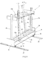
- a ski locker 1 comprises a lower support structure 16, shaped to support the lower end zones 17 of the pairs of skis such as pair of skis 4 from the row of pairs of skis.
- the lower support structure 16 includes two flanges end 18 and 19 transverse supporting an inclined plate 20 transversely outwards. So the end area lower 17 of the pair of skis 4 tends to slide on the plate inclined 20 and to move outward as illustrated by the arrow 21.
- An intermediate support beam 22 is disposed above of the inclined plate 20 and forms a support which limits the transverse displacement of the lower end zone 17 of the pair of skis 4 outwards according to arrow 21.
- An upper support beam 23 is disposed above the intermediate support beam 22 and is offset inwards with respect to said intermediate support beam 22.
- the offset to the interior of the upper support beam 23 relative to the intermediate support beam 22 is determined so as to give the pair of skis 4 the inclination which will be defined later.
- End posts 24 and 25 connect the side members support 22 and 23 and the lower support structure 16.
- the lower support structure 16 can advantageously include casters such as roulette 26, moving on guides or rails 27 and 28 transverse.
- the intermediate support beam 22 comprises a face internal 29 shaped as oblique sawtooth, defining a plurality of triangular intermediate housings such as the housing 30, each intended to receive a pair of skis, and limited by a large facet 31 and a small facet 32.
- the large facet 31 made with the longitudinal direction I-I ( Figure 4) of the ski locker an angle A less than 45 °
- the small facet 32 made with the longitudinal direction I-I an angle B greater than 45 °.
- the facets 31 and 32 of the same intermediate housing 30 can advantageously be perpendicular to each other, and connect by a small radius.
- the large facet 31 of the intermediate housing 30 is connects to the small facet 33 of the adjacent intermediate housing 34 by a top 35 preferably rounded, facilitating orientation automatic pair of skis along the large facet 31 of the intermediate housing 30.
- the upper support beam 23 comprises an external face 36 shaped like oblique sawtooth, defining a plurality upper housing such as housing 37, intended for each receive a pair of skis.
- Each upper housing 37 is limited by a large facet 38 and a small facet 39.
- the large facet 38 has substantially the same orientation as the large facets (31) of the intermediate housings (30), while the small facet 39 has substantially the same orientation as the small facets (32) of the intermediate housings (30).
- the large facets 38 of the support beam upper 23 are generally parallel to each other and parallel with the large facets 31 of the intermediate support beam 22.
- the upper housing 37 triangular and the intermediate housing 40 triangular corresponding define a rectangular structure surrounding a pair of skis.
- the housing upper such as housing 37 are slightly offset longitudinally with respect to the lower housings correspondents such as housing 40 intended to receive and retain the same pair of skis.
- the distance between the small facet 39 of the upper housing 37 and the small facet 41 of the housing less than 40 corresponding is greater than the width of the pair skis.
- a pair of skis held in the accommodation corresponding support rails 22 and 23 is slightly inclined towards the small facet 39 of the support beam upper 23.
- the angle C corresponding to this slight inclination of the pair of skis 4a.
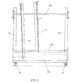
- the upper support beam 23 is offset inwardly relative to the support beam intermediate 22, so that the pairs of skis are held slightly tilted inward. This tilt towards the interior is illustrated by the angle D in FIG. 3.
- the angle A formed between the longitudinal direction I-I and the large facets 31 and 38 of the support beams is included between 20 ° and 45 °, preferably around 30 °, as illustrated in Figure 4.
- the inclined plate 20 makes an angle E with the horizontal (Figure 3) between 30 ° and 60 °, preferably 45 ° about.
- the rack skis includes a double-sided structure, arranged to support two rows of skis, with two opposite inclined plates 20 and 20a, two respective intermediate support beams 22 and 22a, and two respective upper support beams 23 and 23a.
- the housings of the support beams are arranged so that the skis of the opposite rows are oriented in chevrons, with their external faces oriented towards the same longitudinal end locker, as seen in Figures 4 and 7.
- the housing 40 and 37 of the support beams 22 and 23 holding a first row pairs of skis are offset longitudinally with respect to housings 40a and 37a of the support beams 22a and 23a holding the second row of skis.
- the pairs of skis in the adjacent rows are thus nested, so as to reduce the total size of the ski locker.
- the small facets 39 of the upper support rails 23 and 23a have notches 42 adapted to receive and remember the edge of a pair of skis.
- the upper support beam 23 (23a) is adjustable in vertical position along the end posts 24 and 25, and can be locked in any chosen position. We can thus optimize the holding of the skis according to their length and in particular the position of the fasteners, which must not interfere with the support on the support beams 22, 22a, 23 and 23a.
- the installation of skis in a ski locker according to the invention is particularly simple, since the pair of skis automatically engages in the bottom of the housing 40 and 37 with its main faces plated on the large facets of housing 40 and 37, and with its songs resting on the small facets of housing 40 and 37. Extraction of a pair of skis is also very easy, using movements 43 and 44 previously described. These movements are also illustrated by arrows in FIG.
Landscapes
- Warehouses Or Storage Devices (AREA)
Applications Claiming Priority (2)
| Application Number | Priority Date | Filing Date | Title |
|---|---|---|---|
| FR0108783 | 2001-06-29 | ||
| FR0108783A FR2826585B1 (fr) | 2001-06-29 | 2001-06-29 | Casier a skis ranges en oblique |
Publications (1)
| Publication Number | Publication Date |
|---|---|
| EP1270048A1 true EP1270048A1 (de) | 2003-01-02 |
Family
ID=8865047
Family Applications (1)
| Application Number | Title | Priority Date | Filing Date |
|---|---|---|---|
| EP02356117A Withdrawn EP1270048A1 (de) | 2001-06-29 | 2002-06-25 | Regal mit Skis in geneigter Stellung |
Country Status (2)
| Country | Link |
|---|---|
| EP (1) | EP1270048A1 (de) |
| FR (1) | FR2826585B1 (de) |
Cited By (8)
| Publication number | Priority date | Publication date | Assignee | Title |
|---|---|---|---|---|
| WO2005044403A1 (de) * | 2003-11-11 | 2005-05-19 | Helmut Jannach | Vorrichtung zum abstellen und aufbewahren von länglichen, flachen gegenständen |
| NL1027353C2 (nl) * | 2004-10-27 | 2006-05-01 | Machinehandel Wormgoor B V | Ophanginrichting voor ski's en/of snowboards. |
| FR2892904A1 (fr) * | 2005-11-10 | 2007-05-11 | Bernard Chaboud | Presentoir pour articles de sport |
| FR2892903A1 (fr) * | 2005-11-10 | 2007-05-11 | Bernard Chaboud | Presentoir pour skis, surfs et batons. |
| FR2912927A1 (fr) * | 2007-02-27 | 2008-08-29 | Ski Solutions Sarl | Casier a skis perfectionne |
| WO2009049945A1 (de) * | 2007-10-10 | 2009-04-23 | Siemens Transportation Systems Gmbh & Co. Kg | Vorrichtung zur stehenden lagerung von länglichen gegenständen |
| NL2006071C2 (nl) * | 2011-01-26 | 2012-07-30 | Minse Ate Dijk | Skihouder en werkwijze hiervoor. |
| CN103153408A (zh) * | 2010-10-06 | 2013-06-12 | Cwa建筑有限公司 | 滑雪板运输装置 |
Citations (4)
| Publication number | Priority date | Publication date | Assignee | Title |
|---|---|---|---|---|
| CA1231674A (en) | 1985-09-09 | 1988-01-19 | Raymond Tetreault | Ski rack |
| FR2664175A1 (fr) * | 1990-07-09 | 1992-01-10 | Alemany Perrin Francoise | Chariot de transport et de stockage des skis. |
| DE20101764U1 (de) * | 2001-01-31 | 2001-05-03 | Montana Sport International Ag, Stans | Halterung, insbesondere Skihalterung |
| FR2801182A1 (fr) * | 1999-11-18 | 2001-05-25 | Ski Espace | Casier de rangement de skis en position verticale |
-
2001
- 2001-06-29 FR FR0108783A patent/FR2826585B1/fr not_active Expired - Fee Related
-
2002
- 2002-06-25 EP EP02356117A patent/EP1270048A1/de not_active Withdrawn
Patent Citations (4)
| Publication number | Priority date | Publication date | Assignee | Title |
|---|---|---|---|---|
| CA1231674A (en) | 1985-09-09 | 1988-01-19 | Raymond Tetreault | Ski rack |
| FR2664175A1 (fr) * | 1990-07-09 | 1992-01-10 | Alemany Perrin Francoise | Chariot de transport et de stockage des skis. |
| FR2801182A1 (fr) * | 1999-11-18 | 2001-05-25 | Ski Espace | Casier de rangement de skis en position verticale |
| DE20101764U1 (de) * | 2001-01-31 | 2001-05-03 | Montana Sport International Ag, Stans | Halterung, insbesondere Skihalterung |
Cited By (10)
| Publication number | Priority date | Publication date | Assignee | Title |
|---|---|---|---|---|
| WO2005044403A1 (de) * | 2003-11-11 | 2005-05-19 | Helmut Jannach | Vorrichtung zum abstellen und aufbewahren von länglichen, flachen gegenständen |
| NL1027353C2 (nl) * | 2004-10-27 | 2006-05-01 | Machinehandel Wormgoor B V | Ophanginrichting voor ski's en/of snowboards. |
| EP1652561A1 (de) * | 2004-10-27 | 2006-05-03 | Machinehandel Wormgoor B.V. | Vorrichtung zum Aufhängen von Skiern und/oder Snowboards |
| FR2892904A1 (fr) * | 2005-11-10 | 2007-05-11 | Bernard Chaboud | Presentoir pour articles de sport |
| FR2892903A1 (fr) * | 2005-11-10 | 2007-05-11 | Bernard Chaboud | Presentoir pour skis, surfs et batons. |
| FR2912927A1 (fr) * | 2007-02-27 | 2008-08-29 | Ski Solutions Sarl | Casier a skis perfectionne |
| WO2009049945A1 (de) * | 2007-10-10 | 2009-04-23 | Siemens Transportation Systems Gmbh & Co. Kg | Vorrichtung zur stehenden lagerung von länglichen gegenständen |
| AT505843B1 (de) * | 2007-10-10 | 2011-08-15 | Siemens Ag Oesterreich | Vorrichtung zur stehenden lagerung von länglichen gegenständen |
| CN103153408A (zh) * | 2010-10-06 | 2013-06-12 | Cwa建筑有限公司 | 滑雪板运输装置 |
| NL2006071C2 (nl) * | 2011-01-26 | 2012-07-30 | Minse Ate Dijk | Skihouder en werkwijze hiervoor. |
Also Published As
| Publication number | Publication date |
|---|---|
| FR2826585A1 (fr) | 2003-01-03 |
| FR2826585B1 (fr) | 2003-10-24 |
Similar Documents
| Publication | Publication Date | Title |
|---|---|---|
| EP0725464B1 (de) | Sockel für einen Schaltschrank oder dergleichen und Schrank mit einen solchen Sockel | |
| EP0451012A1 (de) | Regalsystem mit abnehmbaren Ablagen | |
| EP1270048A1 (de) | Regal mit Skis in geneigter Stellung | |
| WO1997036520A1 (fr) | Siege compose d'elements assemblables | |
| EP0586291B1 (de) | System eines verstellbaren und zerlegbaren Sitzes, welcher sich auf einer Bodenplatte abstütet | |
| EP1013197B1 (de) | Regale | |
| EP0316372B1 (de) | Zweistöckige schublade zur einlagerung von medikamenten | |
| FR2624839A1 (fr) | Appareil pour le transfert horizontal de plaquettes de silicium notamment | |
| EP0121487B1 (de) | Regal mit durch Keile befestigten Ablageflächen | |
| EP1801023B1 (de) | Lagerungsbehälter mit Schubladen | |
| FR2490173A1 (fr) | Chariot pour le transport et la distribution de documents | |
| FR2461475A1 (fr) | Meuble presentoir notamment pour journaux et revues | |
| EP0738485A1 (de) | Anpassungsfähige modulare Regale | |
| FR2789661A1 (fr) | Chassis de stockage pour bonbonnes de liquide et notamment pour bonbonnes a eau | |
| FR2699897A1 (fr) | Magasin de stockage dynamique. | |
| FR2748698A1 (fr) | Chariot de manutention a moyens de fixation | |
| FR2515127A1 (fr) | Chariot a main | |
| FR2782309A1 (fr) | Palette de stockage et de transport d'elements longilignes | |
| FR2566249A1 (fr) | Installation pour le rangement de skis | |
| EP0543692B1 (de) | Schauanordnung mit einem an vertikalen Kabeln oder Stangen befestigten Pfosten | |
| EP1101425A1 (de) | Verstellbares Aufbausystem auf Profilelementen | |
| BE882238A (fr) | Dispositif de fixation pour rateliers a recipients | |
| FR2700457A1 (fr) | Gondole à embase modulaire. | |
| FR2591453A1 (fr) | Casier, en particulier pour le rangement de bouteilles | |
| FR2517186A1 (fr) | Meuble de rangement modulaire et clips en permettant la realisation |
Legal Events
| Date | Code | Title | Description |
|---|---|---|---|
| PUAI | Public reference made under article 153(3) epc to a published international application that has entered the european phase |
Free format text: ORIGINAL CODE: 0009012 |
|
| AK | Designated contracting states |
Kind code of ref document: A1 Designated state(s): AT BE CH CY DE DK ES FI FR GB GR IE IT LI LU MC NL PT SE TR |
|
| AX | Request for extension of the european patent |
Free format text: AL;LT;LV;MK;RO;SI |
|
| 17P | Request for examination filed |
Effective date: 20030618 |
|
| AKX | Designation fees paid |
Designated state(s): FR |
|
| REG | Reference to a national code |
Ref country code: DE Ref legal event code: 8566 |
|
| GRAP | Despatch of communication of intention to grant a patent |
Free format text: ORIGINAL CODE: EPIDOSNIGR1 |
|
| STAA | Information on the status of an ep patent application or granted ep patent |
Free format text: STATUS: THE APPLICATION IS DEEMED TO BE WITHDRAWN |
|
| 18D | Application deemed to be withdrawn |
Effective date: 20051105 |