EP1270843A1 - Cornière de protection d'angle saillant - Google Patents
Cornière de protection d'angle saillant Download PDFInfo
- Publication number
- EP1270843A1 EP1270843A1 EP02447106A EP02447106A EP1270843A1 EP 1270843 A1 EP1270843 A1 EP 1270843A1 EP 02447106 A EP02447106 A EP 02447106A EP 02447106 A EP02447106 A EP 02447106A EP 1270843 A1 EP1270843 A1 EP 1270843A1
- Authority
- EP
- European Patent Office
- Prior art keywords
- wing
- angle
- plane
- plate
- angle according
- Prior art date
- Legal status (The legal status is an assumption and is not a legal conclusion. Google has not performed a legal analysis and makes no representation as to the accuracy of the status listed.)
- Granted
Links
- 239000011248 coating agent Substances 0.000 claims description 6
- 238000000576 coating method Methods 0.000 claims description 6
- 239000007888 film coating Substances 0.000 claims description 6
- 238000009501 film coating Methods 0.000 claims description 6
- 239000002184 metal Substances 0.000 claims description 3
- 229910052751 metal Inorganic materials 0.000 claims description 3
- 230000001012 protector Effects 0.000 claims description 3
- 238000005520 cutting process Methods 0.000 claims description 2
- 229910001092 metal group alloy Inorganic materials 0.000 claims description 2
- 239000011505 plaster Substances 0.000 abstract description 11
- 229910000746 Structural steel Inorganic materials 0.000 description 8
- 239000000463 material Substances 0.000 description 3
- 230000001681 protective effect Effects 0.000 description 3
- 238000004873 anchoring Methods 0.000 description 1
- 238000012550 audit Methods 0.000 description 1
- 238000012986 modification Methods 0.000 description 1
- 230000004048 modification Effects 0.000 description 1
- 230000035515 penetration Effects 0.000 description 1
Images
Classifications
-
- E—FIXED CONSTRUCTIONS
- E04—BUILDING
- E04F—FINISHING WORK ON BUILDINGS, e.g. STAIRS, FLOORS
- E04F13/00—Coverings or linings, e.g. for walls or ceilings
- E04F13/02—Coverings or linings, e.g. for walls or ceilings of plastic materials hardening after applying, e.g. plaster
- E04F13/04—Bases for plaster
- E04F13/06—Edge-protecting borders
-
- E—FIXED CONSTRUCTIONS
- E04—BUILDING
- E04F—FINISHING WORK ON BUILDINGS, e.g. STAIRS, FLOORS
- E04F13/00—Coverings or linings, e.g. for walls or ceilings
- E04F13/02—Coverings or linings, e.g. for walls or ceilings of plastic materials hardening after applying, e.g. plaster
- E04F13/04—Bases for plaster
- E04F13/06—Edge-protecting borders
- E04F2013/063—Edge-protecting borders for corners
Definitions
- the present invention relates to an angle of protruding corner protector formed, on the first side, of at least one plate to be coated with a film coating, and, on the second side, with a wall to be coated with a wet coating.
- the object of the present invention is to resolve these problems and therefore to develop a so-called mixed angle which allows to adjust it on the plasterboard to obtain a corner protruding from the wall which is perfectly straight.
- a protective angle as indicated at the start, which comprises a first wing which extends in a first plane and which can be fixed in an adjustable manner on said at least one plate, a second wing which extends in a second plane so as to partially cover said wall, and a connecting part which connects the first wing and the second wing and forms an angle between them, this angle projecting with respect to the first wing by a first distance corresponding to a thickness of said film coating, and with respect to the second wing of a second distance corresponding to a thickness of said wet coating.
- the first and second wings are arranged perpendicular to each other.
- This embodiment particularly suitable when the plasterboard is arranged right angle to the wall to be coated.
- the connecting part extends in a third plane which is arranged obliquely to said first plan and second plan audit.
- said third plane forms an angle of 45 ° with said foreground and with said second plane.
- the second wing has cut parts folded parallel to the foreground of the first wing, one end of said at least one plate being arranged between the first wing, these cut-out folded parts of the second wing and part of the second wing which partially covers a slice of said at least a plate. In this way, it is possible to grip an edge of the plate plaster in the angle iron, which favors its adjusted fixing on it.
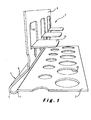
- Figure 1 shows a perspective view of a angle according to the invention.
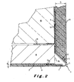
- Figure 2 shows a sectional view of an angle iron according to the invention.
- the angle 1 of protruding corner protection comprises a first wing 2 which extends in a foreground and a second wing 3 which extends in a second plane different from the first. These two wings 2 and 3 are connected by a connecting part 4, which forms an angle 5 between the two wings.
- the plan of the first wing 2 is arranged perpendicular to the plane of the second wing 3 of way to protect a right salient angle, as it is frequently the case in door and window openings or in presence of pilasters or wall projections. It is however understood that the planes of wings 2 and 3 could form an angle other than 90 ° between them, for example to protect window openings splayed at an angle.
- the angle 5 of the connecting part is round.
- This connecting part comprises on either side of the angle 5 a first connecting wing 6 which connects the angle 5 to the second wing 3 and a second connecting wing 7 which connects the angle 5 to the first wing 2.
- the first connecting wing 6 extends in a plane oblique to the to the plans of the first wing 2 and the second wing 3. In this case, this plane forms an angle of 45 ° with each of the planes of the first and second wings 2 and 3.
- the second connecting wing 7 extends in the case illustrated parallel to the first connecting wing 6 on a short distance and the rounded angle 5 is semi-circular in section cross.
- the rounded angle 5 is at one of its ends projecting from the first wing of a first distance d, which in the example illustrated is of the order of 1 mm.
- a first distance d which in the example illustrated is of the order of 1 mm.
- D the second distance
- these distances are given only so illustrative and they can vary within wide limits, depending in particular practical needs in plastering where the salient angle must be protected.
- Such an angle is called “mixed” because it allows the protection of a salient angle formed on one side of a plate 8, by example of a plasterboard, or any other suitable material, which is to be coated with a film coating 9 when capping, and on the other side of a wall or wall 10, which is to be covered with a wet coating 11 traditional, fairly thick.
- an edge of the plate 8 can thus be pressed between the wing 2 of the angle iron, the parts cut out 13 in the shape of legs of the wing 3 and the end, lower on this figure, of the wing 3 against which the edge 14 of the plate 8.
- the distance provided between the cut parts 13 and the first wing 2 is variable depending on the thickness of the plate plaster used.
- the wings of the angle iron according to the invention advantageously have perforations 15 which are intended to allow penetration of the coating during the ceiling and therefore a good anchoring thereof on the angle 1.
- the angle iron 1 can be made of metal, plastic, or any suitable rigid material.
- a laminated metal or metal alloy product which can then be subjected for example to folding, deformation and / or cutting to give it its final shape.
- the angle 1 according to the invention can be fixed so adjustable on the plate or plates 8 which form one side of the projecting angle at protect.
- the angle is pressed along a edge of the plate 8 and it can thus be easily adjusted in a completely vertical position aligned with the wall 10 against which wing 3 is supported.
- the angle iron 1 can then already be permanently fixed on the plate 8, for example by stapling, so that there is no longer any risk of inappropriate movement of the angle iron during capping.
- the fixing on plate 8 will take place by capping only.
- the capping can thus be film on the side of the window opening and allow the application of a thickness continues with wet plaster on the wall side, obtaining a finished angle, perfectly straight.
Landscapes
- Engineering & Computer Science (AREA)
- Architecture (AREA)
- Civil Engineering (AREA)
- Structural Engineering (AREA)
- Working Measures On Existing Buildindgs (AREA)
- Rear-View Mirror Devices That Are Mounted On The Exterior Of The Vehicle (AREA)
- Fittings On The Vehicle Exterior For Carrying Loads, And Devices For Holding Or Mounting Articles (AREA)
- Cable Accessories (AREA)
- Finishing Walls (AREA)
- Building Environments (AREA)
Abstract
Description
une première aile qui s'étend dans un premier plan et qui peut être fixée de manière ajustable sur ladite au moins une plaque,
une deuxième aile qui s'étend dans un deuxième plan de façon à couvrir partiellement ladite paroi, et
une partie de liaison qui relie la première aile et la deuxième aile et forme un angle entre elles, cet angle étant en saillie par rapport à la première aile d'une première distance correspondant à une épaisseur dudit enduit pelliculaire, et par rapport à la deuxième aile d'une deuxième distance correspondant à une épaisseur dudit enduit humide.
Par sa fixation ajustable sur la plaque de plâtre disposée dans l'embrasure, on peut obtenir une cornière rectiligne et verticale qui rattrape les tolérances des ouvrages maçonnés. Cette disposition permet au plafonneur d'appliquer jusqu'à l'angle saillant une épaisseur de plâtre ou enduit humide uniforme et appropriée pour ce type de matériau.
Claims (9)
- Cornière (1) de protection d'angle saillant formé, d'un premier côté, d'au moins une plaque (8) à revêtir d'un enduit pelliculaire (9), et, d'un deuxième côté, d'une paroi (10) à revêtir d'un enduit humide (11),
comprenant
une première aile (2) qui s'étend dans un premier plan et qui peut être fixée de manière ajustable sur ladite au moins une plaque (8),
une deuxième aile (3) qui s'étend dans un deuxième plan de façon à couvrir partiellement ladite paroi (10), et
une partie de liaison (4) qui relie la première aile (2) et la deuxième aile (3) et forme un angle (5) entre elles, cet angle (5) étant en saillie par rapport à la première aile (2) d'une première distance (d) correspondant à une épaisseur dudit enduit pelliculaire (9), et par rapport à la deuxième aile (3) d'une deuxième distance (D) correspondant à une épaisseur dudit enduit humide (11). - Cornière suivant la revendication 1, caractérisée en ce que les première et deuxième ailes (2 et 3) sont disposées perpendiculairement l'une à l'autre.
- Cornière suivant la revendication 2, caractérisée en ce que, entre l'angle (5) de la partie de liaison (4) et la deuxième aile (3), la partie de liaison (4) s'étend dans un troisième plan qui est disposé en oblique par rapport audit premier plan et audit deuxième plan.
- Cornière suivant la revendication 3, caractérisée en ce que ledit troisième plan forme un angle de 45° avec ledit premier plan et avec ledit deuxième plan.
- Cornière suivant l'une des revendications 1 à 4, caractérisée en ce que l'angle (5) de la partie de liaison (4) présente un arrondi.
- Cornière suivant l'une des revendications 1 à 5, caractérisée en ce que la deuxième aile (3) couvre partiellement une tranche (14) de ladite au moins une plaque (8).
- Cornière suivant l'une des revendications 1 à 6, caractérisée en ce que la deuxième aile (3) comporte des parties découpées (13) repliées parallèlement au premier plan de la première aile (2), une extrémité de ladite au moins une plaque (8) étant agencée entre la première aile (2), ces parties découpées (13) repliées de la deuxième aile (3) et une partie de la deuxième aile (3) qui couvre partiellement une tranche (14) de ladite au moins une plaque (8).
- Cornière suivant l'une quelconque des revendications 1 à 7, caractérisée en ce qu'au moins une aile (2, 3) présente des perforations (15).
- Cornière suivant l'une quelconque des revendications 1 à 8, caractérisée en ce qu'elle est réalisée à partir de métal ou alliage métallique laminé, qui a été soumis à des opérations de pliage, déformation et/ou découpage.
Applications Claiming Priority (2)
| Application Number | Priority Date | Filing Date | Title |
|---|---|---|---|
| BE200100392 | 2001-06-08 | ||
| BE2001/0392A BE1014220A3 (fr) | 2001-06-08 | 2001-06-08 | Corniere de protection d'angle saillant. |
Publications (2)
| Publication Number | Publication Date |
|---|---|
| EP1270843A1 true EP1270843A1 (fr) | 2003-01-02 |
| EP1270843B1 EP1270843B1 (fr) | 2008-10-29 |
Family
ID=3897014
Family Applications (1)
| Application Number | Title | Priority Date | Filing Date |
|---|---|---|---|
| EP02447106A Expired - Lifetime EP1270843B1 (fr) | 2001-06-08 | 2002-06-04 | Cornière de protection d'angle saillant |
Country Status (4)
| Country | Link |
|---|---|
| EP (1) | EP1270843B1 (fr) |
| AT (1) | ATE412807T1 (fr) |
| BE (1) | BE1014220A3 (fr) |
| DE (1) | DE60229589D1 (fr) |
Cited By (2)
| Publication number | Priority date | Publication date | Assignee | Title |
|---|---|---|---|---|
| FR3149630A1 (fr) * | 2023-06-12 | 2024-12-13 | Jansen Prefab Nv | Élément de finition d'une partie de mur |
| BE1031692B1 (nl) * | 2023-06-12 | 2025-01-23 | Jansen Prefab Nv | Element voor het afwerken van een wanddeel |
Citations (3)
| Publication number | Priority date | Publication date | Assignee | Title |
|---|---|---|---|---|
| US1615972A (en) * | 1924-03-25 | 1927-02-01 | Claude E Bowers | Corner studding for plaster-board walls |
| US1708688A (en) * | 1927-09-12 | 1929-04-09 | Isaac A Baum | Plaster terminal |
| US3323264A (en) * | 1965-01-22 | 1967-06-06 | Beadex Drywall Specialties Ltd | Drywall corner construction with corner bead |
Family Cites Families (3)
| Publication number | Priority date | Publication date | Assignee | Title |
|---|---|---|---|---|
| DE94683C (fr) * | ||||
| DE2717072B2 (de) * | 1977-04-18 | 1979-03-01 | Hermann 8580 Bayreuth Rannoch | Stumpfwinkelige Mauerwerksecke |
| DE9317812U1 (de) * | 1993-11-22 | 1994-02-10 | Protektorwerk Florenz Maisch GmbH & Co KG, 76571 Gaggenau | Aus einem einstückigen Blechzuschnitt gefertigte Putzeckleiste |
-
2001
- 2001-06-08 BE BE2001/0392A patent/BE1014220A3/fr not_active IP Right Cessation
-
2002
- 2002-06-04 AT AT02447106T patent/ATE412807T1/de not_active IP Right Cessation
- 2002-06-04 EP EP02447106A patent/EP1270843B1/fr not_active Expired - Lifetime
- 2002-06-04 DE DE60229589T patent/DE60229589D1/de not_active Expired - Fee Related
Patent Citations (3)
| Publication number | Priority date | Publication date | Assignee | Title |
|---|---|---|---|---|
| US1615972A (en) * | 1924-03-25 | 1927-02-01 | Claude E Bowers | Corner studding for plaster-board walls |
| US1708688A (en) * | 1927-09-12 | 1929-04-09 | Isaac A Baum | Plaster terminal |
| US3323264A (en) * | 1965-01-22 | 1967-06-06 | Beadex Drywall Specialties Ltd | Drywall corner construction with corner bead |
Cited By (2)
| Publication number | Priority date | Publication date | Assignee | Title |
|---|---|---|---|---|
| FR3149630A1 (fr) * | 2023-06-12 | 2024-12-13 | Jansen Prefab Nv | Élément de finition d'une partie de mur |
| BE1031692B1 (nl) * | 2023-06-12 | 2025-01-23 | Jansen Prefab Nv | Element voor het afwerken van een wanddeel |
Also Published As
| Publication number | Publication date |
|---|---|
| BE1014220A3 (fr) | 2003-06-03 |
| EP1270843B1 (fr) | 2008-10-29 |
| DE60229589D1 (de) | 2008-12-11 |
| ATE412807T1 (de) | 2008-11-15 |
Similar Documents
| Publication | Publication Date | Title |
|---|---|---|
| FR3005481A3 (fr) | Ensemble de porte | |
| BE1012550A6 (fr) | Coffre de volet roulant, joue et profile de recouvrement pour ce coffre. | |
| BE1014220A3 (fr) | Corniere de protection d'angle saillant. | |
| FR2899262A3 (fr) | Plinthe integree dans la maconnerie, en particulier pour des murs constitues ou recouverts de carton-platre | |
| FR2751683A1 (fr) | Elements metalliques pour l'execution de parties de murs exterieurs de batiments | |
| FR2483992A1 (fr) | Fermeture de plinthe pour un revetement mural vertical et procede de mise en place de ce revetement | |
| WO2001002777A1 (fr) | Dispositif de liaison a bride a haute rigidite | |
| EP2549032B1 (fr) | Profilé de finition d'habillage de surface à habiller | |
| EP1715131B1 (fr) | Dispositif pour la réalisation ou la rénovation de portes d'intérieur | |
| FR2624168A1 (fr) | Dispositif pour la construction de revetements de paroi de locaux d'habitation | |
| EP0670408B1 (fr) | Déflecteur pour traverse basse d'un châssis, de porte, fenêtre ou analogue | |
| FR2844166A1 (fr) | Dispositif comprenant au moins deux panneaux articules | |
| EP3551816B1 (fr) | Toiture avec accessoire métallique de couverture | |
| FR2962470A1 (fr) | Ensemble de fermeture avec porte, serrure, corniere et plaque de protection | |
| EP0057655A2 (fr) | Dispositif de jointiement pour revêtement mural du type à parement et sous-couche en mousse | |
| BE520035A (fr) | ||
| FR2519369A1 (fr) | Encadrement metallique d'ouverture exterieure sans bandeau apparent | |
| FR2774411A1 (fr) | Dispositif de bardage | |
| FR2852988A1 (fr) | Dispositif pour la pose de garde-corps en sommet d'un ouvrage et garde-corps equipe de tels dispositifs de pose | |
| FR2884849A1 (fr) | Dispositif pour la realisation ou la renovation de portes d'interieur | |
| BE509025A (fr) | ||
| FR2918406A1 (fr) | Dispositif d'isolation de bas de porte | |
| CH436656A (fr) | Cadre d'embrasure pour construction en maçonnerie | |
| EP1605130A1 (fr) | Joint de porte anti-pince doigts | |
| BE827393A (fr) | Paroi de panneaux pour revetement de facades dans la construction |
Legal Events
| Date | Code | Title | Description |
|---|---|---|---|
| PUAI | Public reference made under article 153(3) epc to a published international application that has entered the european phase |
Free format text: ORIGINAL CODE: 0009012 |
|
| AK | Designated contracting states |
Kind code of ref document: A1 Designated state(s): AT BE CH CY DE DK ES FI FR GB GR IE IT LI LU MC NL PT SE TR |
|
| AX | Request for extension of the european patent |
Free format text: AL;LT;LV;MK;RO;SI |
|
| 17P | Request for examination filed |
Effective date: 20030507 |
|
| AKX | Designation fees paid |
Designated state(s): AT BE CH CY DE DK ES FI FR GB GR IE IT LI LU MC NL PT SE TR |
|
| 17Q | First examination report despatched |
Effective date: 20070813 |
|
| GRAP | Despatch of communication of intention to grant a patent |
Free format text: ORIGINAL CODE: EPIDOSNIGR1 |
|
| GRAS | Grant fee paid |
Free format text: ORIGINAL CODE: EPIDOSNIGR3 |
|
| GRAA | (expected) grant |
Free format text: ORIGINAL CODE: 0009210 |
|
| AK | Designated contracting states |
Kind code of ref document: B1 Designated state(s): AT BE CH CY DE DK ES FI FR GB GR IE IT LI LU MC NL PT SE TR |
|
| REG | Reference to a national code |
Ref country code: GB Ref legal event code: FG4D Free format text: NOT ENGLISH |
|
| REG | Reference to a national code |
Ref country code: CH Ref legal event code: EP |
|
| REG | Reference to a national code |
Ref country code: IE Ref legal event code: FG4D Free format text: LANGUAGE OF EP DOCUMENT: FRENCH |
|
| REF | Corresponds to: |
Ref document number: 60229589 Country of ref document: DE Date of ref document: 20081211 Kind code of ref document: P |
|
| PG25 | Lapsed in a contracting state [announced via postgrant information from national office to epo] |
Ref country code: ES Free format text: LAPSE BECAUSE OF FAILURE TO SUBMIT A TRANSLATION OF THE DESCRIPTION OR TO PAY THE FEE WITHIN THE PRESCRIBED TIME-LIMIT Effective date: 20090209 Ref country code: AT Free format text: LAPSE BECAUSE OF FAILURE TO SUBMIT A TRANSLATION OF THE DESCRIPTION OR TO PAY THE FEE WITHIN THE PRESCRIBED TIME-LIMIT Effective date: 20081029 |
|
| PG25 | Lapsed in a contracting state [announced via postgrant information from national office to epo] |
Ref country code: FI Free format text: LAPSE BECAUSE OF FAILURE TO SUBMIT A TRANSLATION OF THE DESCRIPTION OR TO PAY THE FEE WITHIN THE PRESCRIBED TIME-LIMIT Effective date: 20081029 Ref country code: PT Free format text: LAPSE BECAUSE OF FAILURE TO SUBMIT A TRANSLATION OF THE DESCRIPTION OR TO PAY THE FEE WITHIN THE PRESCRIBED TIME-LIMIT Effective date: 20090330 |
|
| REG | Reference to a national code |
Ref country code: IE Ref legal event code: FD4D |
|
| PG25 | Lapsed in a contracting state [announced via postgrant information from national office to epo] |
Ref country code: IE Free format text: LAPSE BECAUSE OF FAILURE TO SUBMIT A TRANSLATION OF THE DESCRIPTION OR TO PAY THE FEE WITHIN THE PRESCRIBED TIME-LIMIT Effective date: 20081029 Ref country code: DK Free format text: LAPSE BECAUSE OF FAILURE TO SUBMIT A TRANSLATION OF THE DESCRIPTION OR TO PAY THE FEE WITHIN THE PRESCRIBED TIME-LIMIT Effective date: 20081029 |
|
| PG25 | Lapsed in a contracting state [announced via postgrant information from national office to epo] |
Ref country code: SE Free format text: LAPSE BECAUSE OF FAILURE TO SUBMIT A TRANSLATION OF THE DESCRIPTION OR TO PAY THE FEE WITHIN THE PRESCRIBED TIME-LIMIT Effective date: 20090129 Ref country code: IT Free format text: LAPSE BECAUSE OF FAILURE TO SUBMIT A TRANSLATION OF THE DESCRIPTION OR TO PAY THE FEE WITHIN THE PRESCRIBED TIME-LIMIT Effective date: 20081029 |
|
| PLBE | No opposition filed within time limit |
Free format text: ORIGINAL CODE: 0009261 |
|
| STAA | Information on the status of an ep patent application or granted ep patent |
Free format text: STATUS: NO OPPOSITION FILED WITHIN TIME LIMIT |
|
| 26N | No opposition filed |
Effective date: 20090730 |
|
| BERE | Be: lapsed |
Owner name: METAL DEPLOYE BELGE Effective date: 20090630 |
|
| PG25 | Lapsed in a contracting state [announced via postgrant information from national office to epo] |
Ref country code: MC Free format text: LAPSE BECAUSE OF NON-PAYMENT OF DUE FEES Effective date: 20090630 |
|
| REG | Reference to a national code |
Ref country code: CH Ref legal event code: PL |
|
| GBPC | Gb: european patent ceased through non-payment of renewal fee |
Effective date: 20090604 |
|
| NLV4 | Nl: lapsed or anulled due to non-payment of the annual fee |
Effective date: 20100101 |
|
| REG | Reference to a national code |
Ref country code: FR Ref legal event code: ST Effective date: 20100226 |
|
| PG25 | Lapsed in a contracting state [announced via postgrant information from national office to epo] |
Ref country code: LI Free format text: LAPSE BECAUSE OF NON-PAYMENT OF DUE FEES Effective date: 20090630 Ref country code: FR Free format text: LAPSE BECAUSE OF NON-PAYMENT OF DUE FEES Effective date: 20090630 Ref country code: CH Free format text: LAPSE BECAUSE OF NON-PAYMENT OF DUE FEES Effective date: 20090630 |
|
| PG25 | Lapsed in a contracting state [announced via postgrant information from national office to epo] |
Ref country code: GB Free format text: LAPSE BECAUSE OF NON-PAYMENT OF DUE FEES Effective date: 20090604 |
|
| PG25 | Lapsed in a contracting state [announced via postgrant information from national office to epo] |
Ref country code: DE Free format text: LAPSE BECAUSE OF NON-PAYMENT OF DUE FEES Effective date: 20100101 Ref country code: BE Free format text: LAPSE BECAUSE OF NON-PAYMENT OF DUE FEES Effective date: 20090630 |
|
| PG25 | Lapsed in a contracting state [announced via postgrant information from national office to epo] |
Ref country code: NL Free format text: LAPSE BECAUSE OF NON-PAYMENT OF DUE FEES Effective date: 20100101 |
|
| PG25 | Lapsed in a contracting state [announced via postgrant information from national office to epo] |
Ref country code: GR Free format text: LAPSE BECAUSE OF FAILURE TO SUBMIT A TRANSLATION OF THE DESCRIPTION OR TO PAY THE FEE WITHIN THE PRESCRIBED TIME-LIMIT Effective date: 20090130 |
|
| PG25 | Lapsed in a contracting state [announced via postgrant information from national office to epo] |
Ref country code: LU Free format text: LAPSE BECAUSE OF NON-PAYMENT OF DUE FEES Effective date: 20090604 |
|
| PG25 | Lapsed in a contracting state [announced via postgrant information from national office to epo] |
Ref country code: TR Free format text: LAPSE BECAUSE OF FAILURE TO SUBMIT A TRANSLATION OF THE DESCRIPTION OR TO PAY THE FEE WITHIN THE PRESCRIBED TIME-LIMIT Effective date: 20081029 |
|
| PG25 | Lapsed in a contracting state [announced via postgrant information from national office to epo] |
Ref country code: CY Free format text: LAPSE BECAUSE OF FAILURE TO SUBMIT A TRANSLATION OF THE DESCRIPTION OR TO PAY THE FEE WITHIN THE PRESCRIBED TIME-LIMIT Effective date: 20081029 |