EP1274480B1 - Vorrichtung zur positionierung, untersuchung und/oder behandlung, insbesondere im gebiet der endoskopie und/oder minimal invasiver chirurgie - Google Patents
Vorrichtung zur positionierung, untersuchung und/oder behandlung, insbesondere im gebiet der endoskopie und/oder minimal invasiver chirurgie Download PDFInfo
- Publication number
- EP1274480B1 EP1274480B1 EP01921506A EP01921506A EP1274480B1 EP 1274480 B1 EP1274480 B1 EP 1274480B1 EP 01921506 A EP01921506 A EP 01921506A EP 01921506 A EP01921506 A EP 01921506A EP 1274480 B1 EP1274480 B1 EP 1274480B1
- Authority
- EP
- European Patent Office
- Prior art keywords
- bellows
- endpieces
- cable
- fixed
- bases
- Prior art date
- Legal status (The legal status is an assumption and is not a legal conclusion. Google has not performed a legal analysis and makes no representation as to the accuracy of the status listed.)
- Expired - Lifetime
Links
Images

Classifications
-
- F—MECHANICAL ENGINEERING; LIGHTING; HEATING; WEAPONS; BLASTING
- F15—FLUID-PRESSURE ACTUATORS; HYDRAULICS OR PNEUMATICS IN GENERAL
- F15B—SYSTEMS ACTING BY MEANS OF FLUIDS IN GENERAL; FLUID-PRESSURE ACTUATORS, e.g. SERVOMOTORS; DETAILS OF FLUID-PRESSURE SYSTEMS, NOT OTHERWISE PROVIDED FOR
- F15B11/00—Servomotor systems without provision for follow-up action; Circuits therefor
- F15B11/16—Servomotor systems without provision for follow-up action; Circuits therefor with two or more servomotors
- F15B11/20—Servomotor systems without provision for follow-up action; Circuits therefor with two or more servomotors controlling several interacting or sequentially-operating members
-
- A—HUMAN NECESSITIES
- A61—MEDICAL OR VETERINARY SCIENCE; HYGIENE
- A61B—DIAGNOSIS; SURGERY; IDENTIFICATION
- A61B1/00—Instruments for performing medical examinations of the interior of cavities or tubes of the body by visual or photographical inspection, e.g. endoscopes; Illuminating arrangements therefor
- A61B1/005—Flexible endoscopes
- A61B1/0051—Flexible endoscopes with controlled bending of insertion part
- A61B1/0052—Constructional details of control elements, e.g. handles
- A61B1/0053—Constructional details of control elements, e.g. handles using distributed actuators, e.g. artificial muscles
-
- A—HUMAN NECESSITIES
- A61—MEDICAL OR VETERINARY SCIENCE; HYGIENE
- A61M—DEVICES FOR INTRODUCING MEDIA INTO, OR ONTO, THE BODY; DEVICES FOR TRANSDUCING BODY MEDIA OR FOR TAKING MEDIA FROM THE BODY; DEVICES FOR PRODUCING OR ENDING SLEEP OR STUPOR
- A61M25/00—Catheters; Hollow probes
- A61M25/01—Introducing, guiding, advancing, emplacing or holding catheters
- A61M25/0105—Steering means as part of the catheter or advancing means; Markers for positioning
-
- B—PERFORMING OPERATIONS; TRANSPORTING
- B25—HAND TOOLS; PORTABLE POWER-DRIVEN TOOLS; MANIPULATORS
- B25J—MANIPULATORS; CHAMBERS PROVIDED WITH MANIPULATION DEVICES
- B25J18/00—Arms
- B25J18/06—Arms flexible
-
- B—PERFORMING OPERATIONS; TRANSPORTING
- B25—HAND TOOLS; PORTABLE POWER-DRIVEN TOOLS; MANIPULATORS
- B25J—MANIPULATORS; CHAMBERS PROVIDED WITH MANIPULATION DEVICES
- B25J9/00—Program-controlled manipulators
- B25J9/10—Program-controlled manipulators characterised by positioning means for manipulator elements
- B25J9/14—Program-controlled manipulators characterised by positioning means for manipulator elements fluid
- B25J9/142—Program-controlled manipulators characterised by positioning means for manipulator elements fluid comprising inflatable bodies
-
- F—MECHANICAL ENGINEERING; LIGHTING; HEATING; WEAPONS; BLASTING
- F15—FLUID-PRESSURE ACTUATORS; HYDRAULICS OR PNEUMATICS IN GENERAL
- F15B—SYSTEMS ACTING BY MEANS OF FLUIDS IN GENERAL; FLUID-PRESSURE ACTUATORS, e.g. SERVOMOTORS; DETAILS OF FLUID-PRESSURE SYSTEMS, NOT OTHERWISE PROVIDED FOR
- F15B15/00—Fluid-actuated devices for displacing a member from one position to another; Gearing associated therewith
- F15B15/08—Characterised by the construction of the motor unit
- F15B15/10—Characterised by the construction of the motor unit the motor being of diaphragm type
- F15B15/103—Characterised by the construction of the motor unit the motor being of diaphragm type using inflatable bodies that contract when fluid pressure is applied, e.g. pneumatic artificial muscles or McKibben-type actuators
Definitions
- the invention relates to positioning devices, exploration and / or intervention including medical-surgical instruments such as catheters, endoscopes or coeliolaparoscopes. It also relates to various industries that can use this type of device whose size may vary from a few millimeters to several decimetres.
- Medical and surgical instruments are known such as endoscopes or catheters intended to penetrate conduits or cavities of the human body (vessels, digestive tract, urinary tract, etc.) for observation or intervention purposes.
- One of the main difficulties posed by these instruments is that they must be able to deform to follow the curvature of the duct or cavity in which they progress or to take one of the two lanes of a branch line or to circumvent an obstacle, while being the least aggressive possible for the fabrics.
- the problem arises for example in the case where it is sought to treat aneurysm by the installation of an aortic prosthesis.
- instruments are known whose deformation is effected by means of internal cables pulled or pushed so as to bend the instrument in one direction or the other.
- An object of the invention is to provide a positioning device, exploration and / or intervention that can be controlled to obtain pronounced curvatures while being able to have substantial flexibility.
- a positioning, intervention and / or exploration device comprising two bases and at least one cable extending from one to the other of the bases.
- the device comprising at least two bellows directly each fixed to the two bases and means for modifying a fluid pressure in each of the bellows independently of the other bellows or bellows.
- the two bellows make it possible to modify the length of the device by modifying the pressure in each of the bellows and keeping the equal pressures between the bellows at each moment. It can therefore lengthen or shrink the device.
- the bellows pressures can be varied from one another to bend the device.
- these two types of movement can be combined.
- the bellows make it possible to obtain more pronounced curvatures of the device than in conventional devices controlled solely by cable. This is due to the fact that the curvature may result jointly an overpressure in a bellows and a depression in another bellows, while the cables of known devices work essentially in tension.
- the deformation of the device is obtained by playing on the existence and the amplitude of a pressure differential, that is to say by the control of a relative pressure.
- the device allows to choose the absolute pressures prevailing in the bellows to vary the flexibility or rigidity of the device.
- working with high pressures will make the rigid device face external stresses.
- work with low pressures will make the device relatively flexible, deformable and not very aggressive towards its environment, a valuable advantage when an application in the medical field.
- the control of the pressure makes it possible to vary at will the rigidity of the device.
- the curvature of the device is thus optionally controlled by the bellows and / or by one or more cables.
- the device comprises at least three bellows each fixed to the two bases.
- the device can be bent in any direction.
- the device comprises at least one cable extending from one to the other of the bases.
- the or each cable is attached to at least one of the bases and / or is movable relative to at least one of the bases.
- the or each cable is off-center with respect to a longitudinal axis of the device.
- the or each cable extends outside the bellows.
- the device comprises fluid bellows supply tubes, the or each cable passing outside the tubes.
- the or each cable carries at least one shim capable of abutting on at least one of the bases during certain deformations of the device.
- the or each cable carries at least two shims capable of abutting in two opposite directions to one another on the two bases.
- the cables are two in number bellows and arranged on either side of the bellows.
- the device comprises at least three bases arranged in succession, and for each pair of successive bases, at least two bellows each fixed to the two bases.
- the device thus has at least two stages whose curvatures can accumulate or combine.
- the device comprises for each pair of successive bases means for modifying a fluid pressure in each of the bellows fixed to the bases of this pair independently of the other bellows or gussets attached to the bases of this pair.
- the means for modifying the pressure are able to modify the pressure in each of the bellows fixed to the bases of one of the pairs of bases independently of the bellows fixed to the bases of the other pair of bases or of another one of the pairs of bases.
- the two bellows of one of the pairs of bases are in fluid communication with the respective bellows of the other pair of bases or one of the pairs of bases.
- the device comprises at least one spacer arranged to prevent a reconciliation of the two bases or two of the bases beyond a predetermined value.
- each bellows is able to lengthen and shrink in a longitudinal direction of the bellows under the effect of the fluid without substantial modification of a bellows dimension perpendicular to the longitudinal direction.
- the curvatures in two stages can be in different planes or be in the same plane. In this case, they may extend in the same direction or in opposite directions.
- the device comprises a first inner sheath attached to one proximal of the bases and a second outer sheath receiving the bases and slidable on the first inner sheath.
- the fluid is a liquid.
- the device has a free longitudinal space from one end to the other of the device.
- This space can receive elements of intervention, observation, etc.
- the free central longitudinal space allows the passage of instruments or waveguides.
- a medical-surgical instrument comprising a device positioning, exploration and / or intervention according to the invention.
- it is a catheter.
- it is an endoscope.
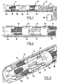
- the positioning device 2 here comprises two modules or stages 4. Each stage 4 comprises two bases 6 of cylindrical shape full but pierced with conducted as will be seen later.
- the four bases 6 are identical and arranged successively with their common axis 8.
- 6a, 6b, 6c and 6d are the successive bases.
- the base 6a is the distal base corresponding to the free end of the device.
- the base 6d is the proximal base and is closest to the fluid control and supply means 18 of the device.
- the bases 6a and 6b form a pair, as well as the bases 6c and 6d.
- To each of these two pairs are associated several bellows 10 here three in number for each pair.
- the six bellows 10 are identical to each other. They have a generally elongate cylindrical shape parallel to the axis 8.
- the three bellows of each pair of bases are regularly distributed around the axis 8.
- Each bellows is fixed by its ends to the two bases of the pair associated with the faces axial ends of the bases. The distal axial end of each bellows is closed.
- the device comprises six ducts 12, one for each bellows 10, all parallel to the axis 8.
- Three of the ducts end at the proximal base 6d on its proximal axial end face opposite to the bellows. They pass through the base 6d and are in fluid communication, inside thereof, with the respective bellows at a proximal axial end thereof.
- the other three ducts 12 pass through the two bases 6d and 6c being regularly distributed around the axis 8 and alternated with the bellows associated with this pair. These three ducts are free to slide through the orifices of these two bases 6c, 6d.
- the three conduits then cross the space between the two modules 4 and arrive at the proximal end of the base 6b.
- the radial position and the spacing of these ducts may be chosen so as to leave a central channel of greater or lesser diameter and a more or less large peripheral space for accommodating a folded annular sleeve (stent) and its possible release device (inflatable balloon).
- the conduits are placed in fluid communication with the three bellows 10 associated with this base. It follows from this arrangement that the two groups of three bellows are offset from each other by a sixth of a turn around the axis 8, in axial view. As for the six ducts 12, they can be evenly distributed around the axis 8. It is the same for the three ducts 12 associated with each pair.
- Each duct 12 is in fluid communication with the bellows 10 with which it is associated and forms with it a sealed assembly with respect to the other ducts and bellows.
- a flexible sheath 14 which can be sealingly connected to the distal base 6a.
- the spacing between the two bases 6b and 6c is preserved, whatever the configuration of the device, by means of spacers 16 contiguous to the sheath 14 and bearing on the axial ends of the bases 6b, 6c opposite.
- the length of these spacers may be chosen so as to obtain a predetermined spacing of the bases 6b and 6c.
- one of these two bases 6b, 6c can be removed so that the distal base of one module forms the proximal base of the other module.
- the sheath 14 can slide to clear the space between the bases 6b and 6c, which allows to drop a folded stent in this space. As a result, the sheath 14 may not be connected to the distal base 6a in a sealed manner. And the three supply conduits located between the bases 6b and 6c may be more radially constricted than the other three ducts to leave a large peripheral space between the bases 6b and 6c.
- the bellows are elastic and can be lengthened, narrowed and / or bent.
- the device comprises means 18 for injecting a pressurized fluid, here a liquid such as physiological saline, into each of the ducts 12 (and the associated bellows). These means make it possible to choose the pressure in each of the bellows, independently of the other bellows. Such means for supplying and controlling the pressure are known per se and have not been shown in detail. In a rudimentary form, it could be a set of six disengageable anti-return syringes associated respectively with the different ducts 12.
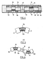
- the six control lines 12 make it possible to deform each stage completely independently as illustrated in FIG. 6, where the two stages have coplanar curvatures but in opposite directions. Precisely, the two floors can be controlled independently of one another. In addition, each of the six bellows can be controlled independently of the others. When the two stages are narrowed or lengthened at the same time, these deformations add up.
- the device according to the invention has active compliance because it can control and control its deformation by a control system. He owns also a passive compliance because it can be deformed to a certain extent under the effect of external stresses. Thus, the higher the pressure in the ducts, the more the device will be rigid. On the contrary, the lower it will be, the more flexible and compliant the device will be. The device thus has a mixed compliance, namely passive and active. The working pressures may be higher or lower than the ambient pressure.
- the deformations obtained by such a device are greater than in the case of a device controlled solely by cables, in particular because the cables generally work in tension.
- the present device can be controlled so that at least one of the bellows works in overpressure while at least one other is in depression so that both act to bend the stage in the same direction.
- the device has a central free space at its axis 8, uninterrupted throughout the device.
- This space extends between the bellows 10, between the ducts 12 and is delimited by a central orifice of the bases 6.
- this space can be housed at choice an instrument, a tool, a camera, a liquid injection pipe, electrical cables, optical fibers, light rays, laser beams, vision device, surgical instruments, needles, biopsy needles, stapling devices, etc. (clamps, pliers, chisel, ...)
- Each module 4 can be miniaturized to have a length of less than 2 cm and a diameter of less than 5 mm.
- each bellows 10 and associated conduit 12 are traversed, here coaxially, by a cable 20.
- the cable is fixed to the base 6a or 6c to which is fixed the distal end closed off the bellows.
- the control means 18 make it possible to pull at will on at least one of the cables 20 without acting on the others.
- the deformation of the device can be obtained by acting on the pressure alone as previously, by action on the cables alone or by action on both at the same time, which allows to obtain deformations, length or curvature particularly important and a variable stiffness.
- the module can shrink the module by reducing the pressure in the bellows. It can also be narrowed by exerting an equal pulling force on three control cables.
- To bend the module it is possible to vary the pressure of one bellows to the other of the module as explained with reference to the first mode. But also, the bellows 10 2 can be simultaneously shortened by traction on the cables, which increases the overall curvature of the device. The combination of the effect of the pressure and the traction of the cable in each bellows makes it possible to vary the stiffness of the device.
- the device comprises two sheaths (which is an aspect independent of the presence of the cables). Indeed, it comprises a second sheath 24 coaxial with the first sheath 14, contiguous internally to the latter, fixed to the proximal end face of the proximal base 6d and extending towards the control means 18. These two sheaths can slide into each other depending on the movements of the distal base 6a relative to the proximal base 6d. It is thus possible to retract the outer sheath while maintaining in place by longitudinal locking the inner sheath.
- the sheath 14 (outer) can slide on the sheath 24 (inner).
- the sheath 24 serves to maintain the longitudinal position of the entire device since, when it is locked, the base 6d abuts on it and can not move back during the retraction of the sheath 14.
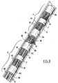
- a third embodiment is illustrated in Figures 7 and 8.
- the device comprises two stages 4, each stage comprising two main bases 6.
- Each stage further comprises an additional and intermediate base 7 extending coaxially between the two bases 6 and halfway there.
- each of the 3 bellows is replaced by a pair of bellows 10 extending in the extension of one another, in fluid communication with each other, and on both sides of the bellows. the intermediate base 7.
- Each of the bellows 10 is therefore connected on the one hand to one of the main bases 6 and on the other hand to the intermediate base 7.
- each bellows of the first mode by two bellows arranged in series and controlled simultaneously increases the amplitude of variation of length and curvature of each stage.
- the intermediate base 7 provides a spacer function by avoiding bellows buckling which could occur if the bellows of the first or second embodiment were of great length.
- each stage is associated in its own right in group with six cables 20.
- the whole of the device therefore comprises twelve cables 20.
- the cables extend out of the bellows and ducts.
- Each pair of bellows is associated with two cables extending on either side of the bellows as seen in FIGS. 7 and 8.
- FIG. 7 illustrates one of the main bases 6 of the proximal stage. 4, that is to say that illustrated in the lower left of Figure 8.
- the base has six main orifices 30 regularly distributed around the central axis 8 of the flare and the central channel 32.
- the orifices 30 correspond, alternately, to the bellows 10 of the proximal stage and the conduits 12 of the distal stage.
- the base has twelve secondary orifices 34 associated in pairs with the main orifices and extending close to them.
- the secondary holes are used for the passage of the cables of the two floors.
- the number of main and secondary ports can be halved to avoid having an unoccupied hole.
- each cable 20 is movable relative to all the bases 6, 7.
- each cable 12 carries a wedge 36 formed for example by a node on the cable or a piece glued or probed to the cable. This wedge prevents the sliding of the cable in the orifice 34 of the base associated in a certain direction beyond a certain limit.
- Each cable carries two shims arranged so that the cable limits the spacing between the two associated bases.
- Each of the most distal wedges is used when it is desired to shrink the device.
- the two shims of each cable are used in cooperation to avoid the plastic deformation of the bellows during an elongation maneuver.
- FIG. 9 illustrates a fourth embodiment which constitutes a variant of the preceding embodiment.
- each base carries six secondary orifices 34 and not twelve.
- the six orifices are arranged in three pairs around the three main orifices 30 associated with the proximal stage. They still serve for the passage of the six associated cables.
- the six cables associated with the distal stage this time pass into the central channel 32 at the proximal stage. They occupy the six secondary orifices at the level of the distal stage.
- the bases can be made of metal, plastic or composite material.
- the bellows can be made of metallic material, plastic or composite.
- the bellows can be secured to the bases sealingly, by gluing, soldering, welding, screwing, riveting, .... It is the same for pressurized fluid supply pipes, which must be flexible and able to resist the maximum pressures that bellows can accept.
- the bases may also have recesses for purging air volumes under pressure (bellows 10, supply pipes 12) when using fluids other than air, including liquids. These recesses can be closed by plugs to ensure tightness after purging.
- the bases may further have recesses to accommodate sensors or attachment systems of tools such as pliers, cutting pliers, scissors, clamp, needle holder, biopsy needle, suction nozzles, etc.
- the device may include position sensors, for example ultrasonic sensors to facilitate its guidance from the outside by the operator.
- the cables can be made of shape memory alloy so as to elongate or retract under the action of temperature changes.
- the bellows preferably comprise electro-deposited nickel.
- the positioning device according to the invention may be designed to be disposable (disposable).
- the number of floors can be one, two, three or more.
- the number of bellows per floor may be equal to two, three or more.
- the bellows of the two stages it would be possible, although this is less advantageous, for the bellows of the two stages to be connected in series at least two by two so that the ducts 12 are three in number and each order two bellows, namely at least one bellows of each floor.
- the two bellows do not can no longer be ordered independently of each other.
- the amplitude of axial deformation of each bellows is increased, and the elongation of each module.
- each bellows may have a shape profile different from the zig-zag shape illustrated in the figures. It may be a cylindrical wall provided to provide elasticity in the longitudinal direction but not in the radial direction.
- the cables may be any plastic material including polymer such as nylon, dacron, kevlar or metal.
Landscapes
- Engineering & Computer Science (AREA)
- Health & Medical Sciences (AREA)
- Life Sciences & Earth Sciences (AREA)
- Mechanical Engineering (AREA)
- Physics & Mathematics (AREA)
- General Health & Medical Sciences (AREA)
- Biomedical Technology (AREA)
- Robotics (AREA)
- Fluid Mechanics (AREA)
- Veterinary Medicine (AREA)
- Biophysics (AREA)
- Public Health (AREA)
- Animal Behavior & Ethology (AREA)
- General Engineering & Computer Science (AREA)
- Heart & Thoracic Surgery (AREA)
- Surgery (AREA)
- Medical Informatics (AREA)
- Analytical Chemistry (AREA)
- Pathology (AREA)
- Molecular Biology (AREA)
- Optics & Photonics (AREA)
- Chemical & Material Sciences (AREA)
- Nuclear Medicine, Radiotherapy & Molecular Imaging (AREA)
- Radiology & Medical Imaging (AREA)
- Pulmonology (AREA)
- Anesthesiology (AREA)
- Hematology (AREA)
- Instruments For Viewing The Inside Of Hollow Bodies (AREA)
- Endoscopes (AREA)
- Surgical Instruments (AREA)
- Eye Examination Apparatus (AREA)
Claims (22)
- Vorrichtung zur Positionierung, zum Eingriff und/oder zur Untersuchung, die zwei Basisteile (6a - 6d, 7) und wenigstens ein Kabel (20), das sich vom einen zum anderen der Basisteile (6a - 6d, 7) erstreckt, umfaßt, wobei das oder jedes Kabel (20) in Bezug auf wenigstens eines der Basisteile (6b, 6d) beweglich ist, dadurch gekennzeichnet, daß sie wenigstens zwei Faltenbalge (10), von denen jeder direkt an den beiden Basisteilen befestigt ist, und Mittel (12, 18) zur Veränderung eines Fluiddruckes in jedem der Faltenbalge unabhängig von dem oder den anderen Faltenbalgen umfaßt.
- Vorrichtung nach Anspruch 1, dadurch gekennzeichnet, daß sie wenigstens drei Faltenbalge (10) umfaßt, von denen jeder an beiden Basisteilen (6a - 6d, 7) befestigt ist.
- Vorrichtung nach einem der Ansprüche 1 bis 2, dadurch gekennzeichnet, daß das oder jedes Kabel (20) an einem der Basisteile (6a-d, 7) befestigt ist.
- Vorrichtung nach einem der Ansprüche 1 bis 3, dadurch gekennzeichnet, daß das oder jedes Kabel (20) in Bezug auf eine Längsachse (8) der Vorrichtung dezentriert ist.
- Vorrichtung nach einem der Ansprüche 1 bis 4, dadurch gekennzeichnet, daß das oder jedes Kabel sich außerhalb der Faltenbalge (10) erstreckt.
- Vorrichtung nach einem der Ansprüche 1 bis 5, dadurch gekennzeichnet, daß sie Röhren (12) zur Versorgung der Faltenbalge (10) mit einem Fluid umfaßt, wobei das oder jedes Kabel (20) außerhalb der Röhren (12) verläuft.
- Vorrichtung nach einem der Ansprüche 1 bis 6, dadurch gekennzeichnet, daß das oder jedes Kabel (20) wenigstens ein Anschlagstück (36) trägt, das dafür geeignet ist, bei bestimmten Deformationen der Vorrichtung auf wenigstens einem der Basisteile in Anschlag zu kommen.
- Vorrichtung nach einem der Ansprüche 1 bis 7, dadurch gekennzeichnet, daß das oder jedes Kabel (20) wenigstens zwei Anschlagstücke (36) trägt, die dafür geeignet sind, in zwei zueinander entgegengesetzten Richtungen auf den beiden Basisteilen (6a - 6d) in Anschlag zu kommen.
- Vorrichtung nach einem der Ansprüche 1 bis 8, dadurch gekennzeichnet, daß die Kabel (20) in einer Anzahl von zwei pro Faltenbalg vorliegen und zu beiden Seiten des Faltenbalgs angeordnet sind.
- Vorrichtung nach einem der Ansprüche 1 bis 9, dadurch gekennzeichnet, daß sie folgendes umfaßt: wenigstens drei Basisteile (6a - 6d), die aufeinanderfolgend angeordnet sind, und für jedes Paar aufeinanderfolgender Basisteile wenigstens zwei Faltenbalge (10), von denen jeder an den beiden Basisteilen befestigt ist.
- Vorrichtung nach Anspruch 10, dadurch gekennzeichnet, daß sie für jedes Paar aufeinanderfolgender Basisteile Mittel (12, 18) umfaßt, um einen Fluiddruck in jedem der Faltenbalge (10), die an den Basisteilen dieses Paares befestigt sind, unabhängig von dem oder den anderen an den Basisteilen dieses Paares befestigten Faltenbalgen zu verändern.
- Vorrichtung nach Anspruch 10 oder 11, dadurch gekennzeichnet, daß die Mittel zur Druckveränderung dafür geeignet sind, den Druck in jedem der Faltenbalge zu verändern, die an den Basisteilen eines der Basisteilpaare befestigt sind, unabhängig von den Faltenbalgen, die an den Basisteilen des anderen Basisteilpaares oder eines weiteren unter den Basisteilpaaren befestigt sind.
- Vorrichtung nach Anspruch 10 oder 11, dadurch gekennzeichnet, daß die zwei Faltenbalge des einen der Basisteilpaare in Fluidkommunikation mit den jeweiligen Faltenbalgen des anderen Basisteilpaares oder eines weiteren unter den Basisteilpaaren stehen.
- Vorrichtung nach einem der Ansprüche 1 bis 13, dadurch gekennzeichnet, daß sie wenigstens ein Zwischenstück (16) umfaßt, das dafür angeordnet ist, eine Annäherung der beiden Basisteile oder von zweien der Basisteile über einen vorbestimmten Wert hinaus zu verhindern.
- Vorrichtung nach einem der Ansprüche 1 bis 14, dadurch gekennzeichnet, daß jeder Faltenbalg dafür geeignet ist, sich in einer Längsrichtung der Faltenbalge unter der Wirkung des Fluids auszudehnen und zusammenzuziehen, und dies ohne eine wesentliche Veränderung einer Abmessung des Faltenbalgs senkrecht zur Längsrichtung.
- Vorrichtung nach einem der Ansprüche 1 bis 15, dadurch gekennzeichnet, daß sie einen inneren ersten Mantel (24), der am einen proximalen (6d) der Basisteile befestigt ist, und einen äußeren zweiten Mantel (14), der die Basisteile (6a - 6d) aufnimmt und der dafür geeignet ist, auf dem inneren ersten Mantel zu gleiten, umfaßt.
- Vorrichtung nach einem der Ansprüche 1 bis 16, dadurch gekennzeichnet, daß das Fluid eine Flüssigkeit ist.
- Vorrichtung nach einem der Ansprüche 1 bis 17, dadurch gekennzeichnet, daß sie von einem Ende der Vorrichtung zum anderen einen längs verlaufenden freien Raum hat.
- Vorrichtung nach Anspruch 18, dadurch gekennzeichnet, daß der längs verlaufende freie Raum dafür eingerichtet ist, die Durchführung von Instrumenten oder Wellenleitern zu gestatten.
- Medizinisch-chirurgisches Instrument, dadurch gekennzeichnet, daß es eine Vorrichtung zur Positionierung, zum Eingriff und/oder zur Behandlung gemäß einem der Ansprüche 1 bis 19 umfaßt.
- Instrument nach Anspruch 20, dadurch gekennzeichnet, daß es sich um einen Katheter handelt.
- Instrument nach Anspruch 20, dadurch gekennzeichnet, daß es sich um ein Endoskop handelt.
Applications Claiming Priority (5)
| Application Number | Priority Date | Filing Date | Title |
|---|---|---|---|
| US55667300A | 2000-04-21 | 2000-04-21 | |
| US556673 | 2000-04-21 | ||
| FR0005179 | 2000-04-21 | ||
| FR0005179A FR2807960B1 (fr) | 2000-04-21 | 2000-04-21 | Dispositif de positionnement, d'exploration et/ou d'intervention notamment dans le domaine de l'endoscopie et/ou de la chirurgie mini-invasive |
| PCT/FR2001/001050 WO2001080935A1 (fr) | 2000-04-21 | 2001-04-06 | Dispositif de positionnement, d'exploration et/ou d'intervention notamment dans le domaine de l'endoscopie et/ou de la chirurgie mini-invasive |
Publications (2)
| Publication Number | Publication Date |
|---|---|
| EP1274480A1 EP1274480A1 (de) | 2003-01-15 |
| EP1274480B1 true EP1274480B1 (de) | 2006-07-05 |
Family
ID=26212358
Family Applications (1)
| Application Number | Title | Priority Date | Filing Date |
|---|---|---|---|
| EP01921506A Expired - Lifetime EP1274480B1 (de) | 2000-04-21 | 2001-04-06 | Vorrichtung zur positionierung, untersuchung und/oder behandlung, insbesondere im gebiet der endoskopie und/oder minimal invasiver chirurgie |
Country Status (8)
| Country | Link |
|---|---|
| US (1) | US6875170B2 (de) |
| EP (1) | EP1274480B1 (de) |
| JP (1) | JP4962750B2 (de) |
| AT (1) | ATE332164T1 (de) |
| AU (1) | AU2001248487A1 (de) |
| CA (1) | CA2406522C (de) |
| DE (1) | DE60121316T2 (de) |
| WO (1) | WO2001080935A1 (de) |
Cited By (5)
| Publication number | Priority date | Publication date | Assignee | Title |
|---|---|---|---|---|
| CN106308939A (zh) * | 2016-08-31 | 2017-01-11 | 北京术锐技术有限公司 | 一种用于驱动柔性连续体结构的驱动单元 |
| CN106308935A (zh) * | 2016-08-31 | 2017-01-11 | 北京术锐技术有限公司 | 一种采用双头螺杆驱动的柔性手术工具系统 |
| CN106308936A (zh) * | 2016-08-31 | 2017-01-11 | 北京术锐技术有限公司 | 一种包含驱动骨的柔性手术工具系统 |
| US11642112B2 (en) | 2016-08-31 | 2023-05-09 | Beijing Surgerii Technology Co., Ltd. | Flexible surgical instrument and driving unit thereof |
| US11903571B2 (en) | 2016-08-31 | 2024-02-20 | Beijing Surgerii Robotics Company Limited | Flexible surgical instrument system with prepositioned drive input |
Families Citing this family (150)
| Publication number | Priority date | Publication date | Assignee | Title |
|---|---|---|---|---|
| US6610007B2 (en) | 2000-04-03 | 2003-08-26 | Neoguide Systems, Inc. | Steerable segmented endoscope and method of insertion |
| US6858005B2 (en) * | 2000-04-03 | 2005-02-22 | Neo Guide Systems, Inc. | Tendon-driven endoscope and methods of insertion |
| US6974411B2 (en) | 2000-04-03 | 2005-12-13 | Neoguide Systems, Inc. | Endoscope with single step guiding apparatus |
| US6984203B2 (en) | 2000-04-03 | 2006-01-10 | Neoguide Systems, Inc. | Endoscope with adjacently positioned guiding apparatus |
| US8517923B2 (en) | 2000-04-03 | 2013-08-27 | Intuitive Surgical Operations, Inc. | Apparatus and methods for facilitating treatment of tissue via improved delivery of energy based and non-energy based modalities |
| US6468203B2 (en) | 2000-04-03 | 2002-10-22 | Neoguide Systems, Inc. | Steerable endoscope and improved method of insertion |
| US8888688B2 (en) | 2000-04-03 | 2014-11-18 | Intuitive Surgical Operations, Inc. | Connector device for a controllable instrument |
| TW524683B (en) | 2001-02-23 | 2003-03-21 | Ras Holding Corp | Surgical blade for use with a surgical tool for making incisions for scleral eye implants |
| AU2002360767A1 (en) * | 2002-01-09 | 2003-07-30 | Neoguide Systems, Inc | Apparatus and method for spectroscopic examination of the colon |
| JP2005514145A (ja) | 2002-01-09 | 2005-05-19 | ネオガイド システムズ, インコーポレイテッド | 内視鏡結腸切除のための装置および方法 |
| DE10209986B4 (de) * | 2002-03-07 | 2004-07-29 | Stm Medizintechnik Starnberg Gmbh | Endoskopschaft mit beweglichem Endabschnitt |
| US8882657B2 (en) | 2003-03-07 | 2014-11-11 | Intuitive Surgical Operations, Inc. | Instrument having radio frequency identification systems and methods for use |
| US20040199052A1 (en) | 2003-04-01 | 2004-10-07 | Scimed Life Systems, Inc. | Endoscopic imaging system |
| US7578786B2 (en) | 2003-04-01 | 2009-08-25 | Boston Scientific Scimed, Inc. | Video endoscope |
| US8118732B2 (en) | 2003-04-01 | 2012-02-21 | Boston Scientific Scimed, Inc. | Force feedback control system for video endoscope |
| US20050245789A1 (en) | 2003-04-01 | 2005-11-03 | Boston Scientific Scimed, Inc. | Fluid manifold for endoscope system |
| US7591783B2 (en) | 2003-04-01 | 2009-09-22 | Boston Scientific Scimed, Inc. | Articulation joint for video endoscope |
| US8182417B2 (en) * | 2004-11-24 | 2012-05-22 | Intuitive Surgical Operations, Inc. | Articulating mechanism components and system for easy assembly and disassembly |
| US8100824B2 (en) | 2003-05-23 | 2012-01-24 | Intuitive Surgical Operations, Inc. | Tool with articulation lock |
| US7090637B2 (en) * | 2003-05-23 | 2006-08-15 | Novare Surgical Systems, Inc. | Articulating mechanism for remote manipulation of a surgical or diagnostic tool |
| US8562640B2 (en) * | 2007-04-16 | 2013-10-22 | Intuitive Surgical Operations, Inc. | Tool with multi-state ratcheted end effector |
| US7410483B2 (en) * | 2003-05-23 | 2008-08-12 | Novare Surgical Systems, Inc. | Hand-actuated device for remote manipulation of a grasping tool |
| US7686826B2 (en) * | 2003-10-30 | 2010-03-30 | Cambridge Endoscopic Devices, Inc. | Surgical instrument |
| US7842028B2 (en) | 2005-04-14 | 2010-11-30 | Cambridge Endoscopic Devices, Inc. | Surgical instrument guide device |
| US7338513B2 (en) * | 2003-10-30 | 2008-03-04 | Cambridge Endoscopic Devices, Inc. | Surgical instrument |
| DE102004003166B4 (de) * | 2004-01-21 | 2011-09-15 | Siemens Ag | Katheter |
| DE102004003082B4 (de) * | 2004-01-21 | 2011-01-20 | Siemens Ag | Kathetereinrichtung |
| US7828808B2 (en) | 2004-06-07 | 2010-11-09 | Novare Surgical Systems, Inc. | Link systems and articulation mechanisms for remote manipulation of surgical or diagnostic tools |
| US7678117B2 (en) | 2004-06-07 | 2010-03-16 | Novare Surgical Systems, Inc. | Articulating mechanism with flex-hinged links |
| US7479106B2 (en) | 2004-09-30 | 2009-01-20 | Boston Scientific Scimed, Inc. | Automated control of irrigation and aspiration in a single-use endoscope |
| EP1799095A2 (de) | 2004-09-30 | 2007-06-27 | Boston Scientific Scimed, Inc. | Adapter zur verwendung mit einem digitalen bildgebenden medizinprodukt |
| US8353860B2 (en) | 2004-09-30 | 2013-01-15 | Boston Scientific Scimed, Inc. | Device for obstruction removal with specific tip structure |
| US7597662B2 (en) | 2004-09-30 | 2009-10-06 | Boston Scientific Scimed, Inc. | Multi-fluid delivery system |
| US7241263B2 (en) | 2004-09-30 | 2007-07-10 | Scimed Life Systems, Inc. | Selectively rotatable shaft coupler |
| US8083671B2 (en) | 2004-09-30 | 2011-12-27 | Boston Scientific Scimed, Inc. | Fluid delivery system for use with an endoscope |
| JP2008514363A (ja) | 2004-09-30 | 2008-05-08 | ボストン サイエンティフィック リミテッド | 電気外科用途において使用するための多機能内視鏡システム |
| US7785252B2 (en) | 2004-11-23 | 2010-08-31 | Novare Surgical Systems, Inc. | Articulating sheath for flexible instruments |
| US9700334B2 (en) * | 2004-11-23 | 2017-07-11 | Intuitive Surgical Operations, Inc. | Articulating mechanisms and link systems with torque transmission in remote manipulation of instruments and tools |
| US20060201130A1 (en) * | 2005-01-31 | 2006-09-14 | Danitz David J | Articulating mechanisms with joint assembly and manual handle for remote manipulation of instruments and tools |
| DE102005022132B4 (de) * | 2005-05-12 | 2007-01-25 | Invendo Medical Gmbh | Diskontinuierlicher Linearantrieb |
| US8097003B2 (en) | 2005-05-13 | 2012-01-17 | Boston Scientific Scimed, Inc. | Endoscopic apparatus with integrated variceal ligation device |
| US7846107B2 (en) | 2005-05-13 | 2010-12-07 | Boston Scientific Scimed, Inc. | Endoscopic apparatus with integrated multiple biopsy device |
| JP5000503B2 (ja) * | 2005-06-14 | 2012-08-15 | オリンパスメディカルシステムズ株式会社 | 内視鏡処置具 |
| US8409175B2 (en) * | 2005-07-20 | 2013-04-02 | Woojin Lee | Surgical instrument guide device |
| US8052597B2 (en) | 2005-08-30 | 2011-11-08 | Boston Scientific Scimed, Inc. | Method for forming an endoscope articulation joint |
| JP4814586B2 (ja) * | 2005-09-02 | 2011-11-16 | オリンパス株式会社 | 内視鏡装置 |
| JP4891583B2 (ja) * | 2005-09-02 | 2012-03-07 | オリンパス株式会社 | 内視鏡装置 |
| EP3788944B1 (de) | 2005-11-22 | 2024-02-28 | Intuitive Surgical Operations, Inc. | System zur bestimmung der form eines biegbaren instruments |
| WO2007062066A2 (en) | 2005-11-23 | 2007-05-31 | Neoguide Systems, Inc. | Non-metallic, multi-strand control cable for steerable instruments |
| US7967759B2 (en) | 2006-01-19 | 2011-06-28 | Boston Scientific Scimed, Inc. | Endoscopic system with integrated patient respiratory status indicator |
| US8888684B2 (en) | 2006-03-27 | 2014-11-18 | Boston Scientific Scimed, Inc. | Medical devices with local drug delivery capabilities |
| US8202265B2 (en) | 2006-04-20 | 2012-06-19 | Boston Scientific Scimed, Inc. | Multiple lumen assembly for use in endoscopes or other medical devices |
| US7955255B2 (en) | 2006-04-20 | 2011-06-07 | Boston Scientific Scimed, Inc. | Imaging assembly with transparent distal cap |
| US8568299B2 (en) | 2006-05-19 | 2013-10-29 | Intuitive Surgical Operations, Inc. | Methods and apparatus for displaying three-dimensional orientation of a steerable distal tip of an endoscope |
| US8105350B2 (en) * | 2006-05-23 | 2012-01-31 | Cambridge Endoscopic Devices, Inc. | Surgical instrument |
| US7615067B2 (en) | 2006-06-05 | 2009-11-10 | Cambridge Endoscopic Devices, Inc. | Surgical instrument |
| US7862554B2 (en) | 2007-04-16 | 2011-01-04 | Intuitive Surgical Operations, Inc. | Articulating tool with improved tension member system |
| US8409244B2 (en) * | 2007-04-16 | 2013-04-02 | Intuitive Surgical Operations, Inc. | Tool with end effector force limiter |
| US9561045B2 (en) * | 2006-06-13 | 2017-02-07 | Intuitive Surgical Operations, Inc. | Tool with rotation lock |
| US8029531B2 (en) | 2006-07-11 | 2011-10-04 | Cambridge Endoscopic Devices, Inc. | Surgical instrument |
| US7708758B2 (en) * | 2006-08-16 | 2010-05-04 | Cambridge Endoscopic Devices, Inc. | Surgical instrument |
| US20080051704A1 (en) * | 2006-08-28 | 2008-02-28 | Patel Rajnikant V | Catheter and system for using same |
| US7648519B2 (en) | 2006-09-13 | 2010-01-19 | Cambridge Endoscopic Devices, Inc. | Surgical instrument |
| US12082781B2 (en) * | 2007-01-30 | 2024-09-10 | Loma Vista Medical, Inc. | Biological navigation device |
| WO2008095046A2 (en) * | 2007-01-30 | 2008-08-07 | Loma Vista Medical, Inc., | Biological navigation device |
| EP2124800B1 (de) * | 2007-02-15 | 2010-11-17 | Hansen Medical, Inc. | Medizinisches roboterinstrumentensystem |
| KR100883337B1 (ko) * | 2007-03-19 | 2009-02-11 | 한양대학교 산학협력단 | 내시경 및 이의 동작 제어시스템 |
| US20080262492A1 (en) * | 2007-04-11 | 2008-10-23 | Cambridge Endoscopic Devices, Inc. | Surgical Instrument |
| US8409245B2 (en) * | 2007-05-22 | 2013-04-02 | Woojin Lee | Surgical instrument |
| JP5214187B2 (ja) * | 2007-07-13 | 2013-06-19 | オリンパスメディカルシステムズ株式会社 | 内視鏡、内視鏡装置および内視鏡装置の作動方法 |
| US9005238B2 (en) * | 2007-08-23 | 2015-04-14 | Covidien Lp | Endoscopic surgical devices |
| US8257386B2 (en) * | 2007-09-11 | 2012-09-04 | Cambridge Endoscopic Devices, Inc. | Surgical instrument |
| US9220398B2 (en) | 2007-10-11 | 2015-12-29 | Intuitive Surgical Operations, Inc. | System for managing Bowden cables in articulating instruments |
| US8083759B2 (en) * | 2007-11-02 | 2011-12-27 | Refocus Ocular, Inc. | Apparatuses and methods for forming incisions in ocular tissue |
| US20090171147A1 (en) * | 2007-12-31 | 2009-07-02 | Woojin Lee | Surgical instrument |
| US20130090763A1 (en) * | 2008-01-25 | 2013-04-11 | The Trustees Of Columibia University In The City Of The City Of New York | Systems and methods for force sensing in a robot |
| US10512392B2 (en) | 2008-02-06 | 2019-12-24 | Intuitive Surgical Operations, Inc. | Segmented instrument having braking capabilities |
| DE102008009919A1 (de) * | 2008-02-15 | 2009-08-27 | Fraunhofer-Gesellschaft zur Förderung der angewandten Forschung e.V. | Instrument zum Einführen in unzugängliche Räume |
| US8182418B2 (en) | 2008-02-25 | 2012-05-22 | Intuitive Surgical Operations, Inc. | Systems and methods for articulating an elongate body |
| KR101336377B1 (ko) | 2008-04-18 | 2013-12-04 | 포티메딕스 서지컬 비.브이. | 내시경 용례 등을 위한 장비 |
| EP2278908B1 (de) * | 2008-04-27 | 2021-06-02 | Loma Vista Medical, Inc. | Biologisches navigationsgerät |
| US20090299327A1 (en) | 2008-06-02 | 2009-12-03 | Lorna Vista Medical, Inc. | Inflatable medical devices |
| US8968355B2 (en) | 2008-08-04 | 2015-03-03 | Covidien Lp | Articulating surgical device |
| US8801752B2 (en) * | 2008-08-04 | 2014-08-12 | Covidien Lp | Articulating surgical device |
| US8465475B2 (en) | 2008-08-18 | 2013-06-18 | Intuitive Surgical Operations, Inc. | Instrument with multiple articulation locks |
| US20100249497A1 (en) * | 2009-03-30 | 2010-09-30 | Peine William J | Surgical instrument |
| FR2943907B1 (fr) | 2009-04-03 | 2012-08-03 | Univ Pierre Et Marie Curie Paris 6 | Instrument chirurgical. |
| FR2943906B1 (fr) | 2009-04-03 | 2013-03-22 | Univ Pierre Et Marie Curie Paris 6 | Instrument chirurgical. |
| DE102009022118A1 (de) * | 2009-05-20 | 2010-11-25 | Karl Storz Gmbh & Co. Kg | Endoskop |
| DE202009012793U1 (de) * | 2009-05-29 | 2010-01-28 | Aesculap Ag | Chirurgisches Instrument |
| GB0910951D0 (en) | 2009-06-24 | 2009-08-05 | Imp Innovations Ltd | Joint arrangement |
| US20110022078A1 (en) | 2009-07-23 | 2011-01-27 | Cameron Dale Hinman | Articulating mechanism |
| US20110090331A1 (en) * | 2009-10-15 | 2011-04-21 | Perceptron, Inc. | Articulating imager for video borescope |
| US20110112517A1 (en) * | 2009-11-06 | 2011-05-12 | Peine Willliam J | Surgical instrument |
| GB0920938D0 (en) * | 2009-11-30 | 2010-01-13 | Imp Innovations Ltd | Steerable probes |
| EP2335884B1 (de) * | 2009-12-15 | 2012-09-05 | FESTO AG & Co. KG | Fluidisch betreibbarer Manipulator |
| KR101173619B1 (ko) | 2010-04-29 | 2012-08-13 | 한국과학기술원 | 내시경 수술용 로봇장치 |
| FR2960468B1 (fr) * | 2010-05-31 | 2013-03-29 | Commissariat Energie Atomique | Structure gonflable articulee et bras robotise comportant une telle structure |
| US9592119B2 (en) | 2010-07-13 | 2017-03-14 | C.R. Bard, Inc. | Inflatable medical devices |
| US8974372B2 (en) | 2010-08-25 | 2015-03-10 | Barry M. Fell | Path-following robot |
| US10188436B2 (en) | 2010-11-09 | 2019-01-29 | Loma Vista Medical, Inc. | Inflatable medical devices |
| CN102525380B (zh) * | 2010-12-23 | 2016-03-30 | 德昌电机(深圳)有限公司 | 弯曲结构及使用该弯曲结构的内窥装置、胃管和机械关节 |
| US9168050B1 (en) | 2011-03-24 | 2015-10-27 | Cambridge Endoscopic Devices, Inc. | End effector construction |
| US9161771B2 (en) | 2011-05-13 | 2015-10-20 | Intuitive Surgical Operations Inc. | Medical instrument with snake wrist structure |
| US8603135B2 (en) * | 2011-07-20 | 2013-12-10 | Covidien Lp | Articulating surgical apparatus |
| US8597318B2 (en) | 2011-08-08 | 2013-12-03 | Refocus Group, Inc. | Apparatus and method for forming incisions in ocular tissue |
| US9119639B2 (en) * | 2011-08-09 | 2015-09-01 | DePuy Synthes Products, Inc. | Articulated cavity creator |
| US20130158355A1 (en) * | 2011-12-16 | 2013-06-20 | Pioneer Medical Instrument Co., Ltd. | Two-way endoscope steering mechanism and four-way endoscope steering mechanism |
| WO2013184192A2 (en) * | 2012-05-12 | 2013-12-12 | Massachusetts Institute Of Technology | Continuum style manipulator actuated with phase change media |
| US9186049B2 (en) * | 2012-10-25 | 2015-11-17 | Choon Kee Lee | Extensible and guidable apparatus |
| US9624911B1 (en) | 2012-10-26 | 2017-04-18 | Sunfolding, Llc | Fluidic solar actuator |
| WO2014111943A2 (en) * | 2013-01-21 | 2014-07-24 | G.I. View Ltd. | Integrated steering device |
| US9439693B2 (en) | 2013-02-01 | 2016-09-13 | DePuy Synthes Products, Inc. | Steerable needle assembly for use in vertebral body augmentation |
| US20140296869A1 (en) | 2013-03-14 | 2014-10-02 | Intuitive Surgical Operations, Inc. | Surgical instrument shaft |
| JP6033408B2 (ja) * | 2013-03-28 | 2016-11-30 | オリンパス株式会社 | 外套管および処置具 |
| US9357984B2 (en) | 2013-04-23 | 2016-06-07 | Covidien Lp | Constant value gap stabilizer for articulating links |
| DE102014204849A1 (de) * | 2014-03-17 | 2015-09-17 | Continental Automotive Gmbh | Verfahren zur Herstellung einer mechanischen Vorrichtung mit einem Übertragungselement sowie Übertragungselement zur Übertragung einer Stellgröße |
| JP6306156B2 (ja) * | 2014-04-10 | 2018-04-04 | シャープ株式会社 | 屈曲装置 |
| US10492669B2 (en) * | 2014-05-30 | 2019-12-03 | Sharp Kabushiki Kaisha | Bending device, control device, and medical instrument |
| DE102014008187B4 (de) * | 2014-06-04 | 2017-04-06 | Schölly Fiberoptic GmbH | Hochdruck-Reinigungsinstrument und Reinigungsverfahren |
| US10413372B2 (en) * | 2014-07-28 | 2019-09-17 | Intuitive Surgical Operations, Inc. | Guide apparatus for delivery of a flexible instrument and methods of use |
| MX367676B (es) | 2015-01-30 | 2019-08-30 | Sunfolding Inc | Método y sistema de accionador fluídico. |
| EP3274039B1 (de) | 2015-03-27 | 2020-04-22 | Project Moray, Inc. | Fluidantriebssystem für kathetergelenk und andere verwendungen |
| US10010246B2 (en) * | 2015-05-28 | 2018-07-03 | Roland Quaye | Steerable endoscopes |
| CN108601925B (zh) | 2015-12-04 | 2021-06-29 | 项目莫里股份有限公司 | 用于导管和其他用途的输入和铰接系统 |
| US10500373B2 (en) | 2015-12-04 | 2019-12-10 | Project Moray, Inc. | Lateral articulation anchors for catheters and other uses |
| WO2017143170A1 (en) * | 2016-02-17 | 2017-08-24 | Keith Phillip Laby | Local contraction of flexible bodies using balloon expansion for extension-contraction catheter articulation and other uses |
| WO2017165810A1 (en) | 2016-03-25 | 2017-09-28 | Phillip Laby | Fluid-actuated sheath displacement and articulation behavior improving systems, devices, and methods for catheters, continuum manipulators, and other uses |
| US11420021B2 (en) | 2016-03-25 | 2022-08-23 | Project Moray, Inc. | Fluid-actuated displacement for catheters, continuum manipulators, and other uses |
| WO2017172902A1 (en) | 2016-03-29 | 2017-10-05 | Other Lab, Llc | Fluidic robotic actuator system and method |
| NL2016900B1 (en) | 2016-06-06 | 2017-12-13 | Fortimedix Surgical B V | Steerable instrument comprising a cylindrical diameter adaptation section |
| WO2018064398A1 (en) | 2016-09-28 | 2018-04-05 | Project Moray, Inc. | Arrhythmia diagnostic and/or therapy delivery methods and devices, and robotic systems for other uses |
| WO2018064400A1 (en) | 2016-09-28 | 2018-04-05 | Project Moray, Inc. | Base station, charging station, and/or server for robotic catheter systems and other uses, and improved articulated devices and systems |
| GB201617934D0 (en) * | 2016-10-24 | 2016-12-07 | Univ Dundee | Actuators |
| GB201703056D0 (en) * | 2017-02-24 | 2017-04-12 | King S College London | Soft locomotive device for endoscopy with adaptive anchoring |
| JP6647235B2 (ja) * | 2017-02-28 | 2020-02-14 | キヤノン株式会社 | ワイヤ駆動マニピュレータ |
| EP3612774A4 (de) | 2017-04-17 | 2021-01-06 | Sunfolding, Inc. | Schaltkreissystem und verfahren mit pneumatischer betätigung |
| WO2018200537A1 (en) | 2017-04-25 | 2018-11-01 | Project Moray, Inc. | Matrix supported balloon articulation systems, devices, and methods for catheters and other users |
| WO2019034863A1 (en) * | 2017-08-15 | 2019-02-21 | University Of Dundee | SOFT ACTUATOR |
| CN111225624A (zh) | 2017-08-23 | 2020-06-02 | 瑞福克斯集团公司 | 一种用于在眼部组织形成切口且具有提供可视性端头的外科手术工具及其相关装置和方法 |
| AU2019277145B2 (en) | 2018-05-29 | 2023-06-08 | Sunfolding, Inc. | Tubular fluidic actuator system and method |
| JP6913246B2 (ja) * | 2018-06-04 | 2021-08-04 | オリンパス株式会社 | 剛性可変装置および内視鏡 |
| US10646104B1 (en) | 2018-10-29 | 2020-05-12 | G.I. View Ltd. | Disposable endoscope |
| US11559191B2 (en) | 2018-10-29 | 2023-01-24 | G.I. View Ltd. | Insertion unit for medical instruments and an intubation system thereof |
| CN109452976B (zh) | 2018-12-28 | 2021-01-15 | 北京术锐技术有限公司 | 一种柔性手术工具系统 |
| GB201908949D0 (en) * | 2019-06-22 | 2019-08-07 | Univ Dundee | A robot for endoscopy |
| EP4169157A1 (de) | 2020-06-22 | 2023-04-26 | Sunfolding, Inc. | Verriegelungs-, dämpfungs- und betätigungssysteme und verfahren für sonnenfolger |
| KR102700627B1 (ko) * | 2021-12-30 | 2024-08-30 | 주식회사 에어스 | 탄성체 적층 구조의 의료용 엔드 이펙터 |
| JP7468760B1 (ja) * | 2023-07-13 | 2024-04-16 | オムロン株式会社 | ペンデバイス、プログラム、及びペンシステム |
| US12589489B2 (en) * | 2024-02-28 | 2026-03-31 | International Business Machines Corporation | Pressurized sleeve for routing of linear components |
Family Cites Families (30)
| Publication number | Priority date | Publication date | Assignee | Title |
|---|---|---|---|---|
| US4140126A (en) | 1977-02-18 | 1979-02-20 | Choudhury M Hasan | Method for performing aneurysm repair |
| US4676228A (en) * | 1985-10-25 | 1987-06-30 | Krasner Jerome L | Medical apparatus having inflatable cuffs and a middle expandable section |
| US4832473A (en) * | 1987-02-06 | 1989-05-23 | Olympus Optical Co., Ltd. | Endoscope with elastic actuator comprising a synthetic rubber tube with only radial expansion controlled by a mesh-like tube |
| US4794912A (en) | 1987-08-17 | 1989-01-03 | Welch Allyn, Inc. | Borescope or endoscope with fluid dynamic muscle |
| US4893613A (en) * | 1987-11-25 | 1990-01-16 | Hake Lawrence W | Endoscope construction with means for controlling rigidity and curvature of flexible endoscope tube |
| JPH0239117A (ja) * | 1988-07-29 | 1990-02-08 | Olympus Optical Co Ltd | 内視鏡装置 |
| US5254088A (en) | 1990-02-02 | 1993-10-19 | Ep Technologies, Inc. | Catheter steering mechanism |
| JPH04218135A (ja) * | 1990-02-20 | 1992-08-07 | Olympus Optical Co Ltd | 内視鏡 |
| US5179934A (en) * | 1990-02-20 | 1993-01-19 | Olympus Optical Co., Ltd. | Endoscope |
| JPH04176429A (ja) * | 1990-11-09 | 1992-06-24 | Olympus Optical Co Ltd | 内視鏡 |
| FR2659397B1 (fr) | 1990-03-06 | 1994-06-03 | Inst Nat Sciences Appliq Lyon | Actionneur asservi par un fluide sous pression, pour petits mouvements. |
| US5018506A (en) * | 1990-06-18 | 1991-05-28 | Welch Allyn, Inc. | Fluid controlled biased bending neck |
| US5203319A (en) * | 1990-06-18 | 1993-04-20 | Welch Allyn, Inc. | Fluid controlled biased bending neck |
| US5042707A (en) | 1990-10-16 | 1991-08-27 | Taheri Syde A | Intravascular stapler, and method of operating same |
| AU660444B2 (en) | 1991-02-15 | 1995-06-29 | Ingemar H. Lundquist | Torquable catheter and method |
| JPH0531067A (ja) * | 1991-08-02 | 1993-02-09 | Olympus Optical Co Ltd | 可撓管の湾曲装置 |
| JPH0564627A (ja) * | 1991-09-09 | 1993-03-19 | Olympus Optical Co Ltd | 管内検査装置 |
| US5297443A (en) * | 1992-07-07 | 1994-03-29 | Wentz John D | Flexible positioning appendage |
| JPH0647052A (ja) * | 1992-07-30 | 1994-02-22 | Olympus Optical Co Ltd | 管状挿入具の湾曲操作装置 |
| WO1996035877A1 (de) * | 1995-05-09 | 1996-11-14 | Ati Alternative Technische Innovation Ag | Fluidisches betätigungsorgan |
| US5591195A (en) | 1995-10-30 | 1997-01-07 | Taheri; Syde | Apparatus and method for engrafting a blood vessel |
| AUPN775296A0 (en) | 1996-01-25 | 1996-02-22 | Endogad Research Pty Limited | Directional catheter |
| NL1002254C2 (nl) * | 1996-02-06 | 1997-08-07 | Cordis Europ | Bestuurd buigbare catheter. |
| WO1998031944A1 (en) | 1997-01-17 | 1998-07-23 | Rathnakar Yadama | Flexible shaft |
| US6123699A (en) | 1997-09-05 | 2000-09-26 | Cordis Webster, Inc. | Omni-directional steerable catheter |
| US5897529A (en) | 1997-09-05 | 1999-04-27 | Cordis Webster, Inc. | Steerable deflectable catheter having improved flexibility |
| EP1032450A1 (de) | 1997-10-31 | 2000-09-06 | Neurovasx, Inc. | Submikrokatheter |
| JP3573648B2 (ja) * | 1998-03-19 | 2004-10-06 | オリンパス株式会社 | 内視鏡 |
| US6162171A (en) * | 1998-12-07 | 2000-12-19 | Wan Sing Ng | Robotic endoscope and an autonomous pipe robot for performing endoscopic procedures |
| JP2000219134A (ja) * | 1999-02-01 | 2000-08-08 | Shigeo Kato | 管内走行装置 |
-
2001
- 2001-04-06 CA CA002406522A patent/CA2406522C/fr not_active Expired - Fee Related
- 2001-04-06 JP JP2001578029A patent/JP4962750B2/ja not_active Expired - Fee Related
- 2001-04-06 EP EP01921506A patent/EP1274480B1/de not_active Expired - Lifetime
- 2001-04-06 AT AT01921506T patent/ATE332164T1/de not_active IP Right Cessation
- 2001-04-06 AU AU2001248487A patent/AU2001248487A1/en not_active Abandoned
- 2001-04-06 DE DE60121316T patent/DE60121316T2/de not_active Expired - Lifetime
- 2001-04-06 WO PCT/FR2001/001050 patent/WO2001080935A1/fr not_active Ceased
-
2002
- 2002-10-21 US US10/274,454 patent/US6875170B2/en not_active Expired - Fee Related
Cited By (9)
| Publication number | Priority date | Publication date | Assignee | Title |
|---|---|---|---|---|
| CN106308939A (zh) * | 2016-08-31 | 2017-01-11 | 北京术锐技术有限公司 | 一种用于驱动柔性连续体结构的驱动单元 |
| CN106308935A (zh) * | 2016-08-31 | 2017-01-11 | 北京术锐技术有限公司 | 一种采用双头螺杆驱动的柔性手术工具系统 |
| CN106308936A (zh) * | 2016-08-31 | 2017-01-11 | 北京术锐技术有限公司 | 一种包含驱动骨的柔性手术工具系统 |
| CN106308936B (zh) * | 2016-08-31 | 2018-12-07 | 北京术锐技术有限公司 | 一种包含驱动骨的柔性手术工具系统 |
| CN106308935B (zh) * | 2016-08-31 | 2018-12-07 | 北京术锐技术有限公司 | 一种采用双头螺杆驱动的柔性手术工具系统 |
| CN106308939B (zh) * | 2016-08-31 | 2019-01-08 | 北京术锐技术有限公司 | 一种用于驱动柔性连续体结构的驱动单元 |
| US11484373B2 (en) | 2016-08-31 | 2022-11-01 | Beijing Surgerii Technology Co., Ltd. | Flexible surgical instrument system |
| US11642112B2 (en) | 2016-08-31 | 2023-05-09 | Beijing Surgerii Technology Co., Ltd. | Flexible surgical instrument and driving unit thereof |
| US11903571B2 (en) | 2016-08-31 | 2024-02-20 | Beijing Surgerii Robotics Company Limited | Flexible surgical instrument system with prepositioned drive input |
Also Published As
| Publication number | Publication date |
|---|---|
| EP1274480A1 (de) | 2003-01-15 |
| JP2003530975A (ja) | 2003-10-21 |
| JP4962750B2 (ja) | 2012-06-27 |
| AU2001248487A1 (en) | 2001-11-07 |
| CA2406522A1 (fr) | 2001-11-01 |
| US6875170B2 (en) | 2005-04-05 |
| DE60121316D1 (de) | 2006-08-17 |
| CA2406522C (fr) | 2009-07-14 |
| ATE332164T1 (de) | 2006-07-15 |
| WO2001080935A1 (fr) | 2001-11-01 |
| DE60121316T2 (de) | 2007-08-02 |
| US20030149338A1 (en) | 2003-08-07 |
Similar Documents
| Publication | Publication Date | Title |
|---|---|---|
| CA2406522C (fr) | Dispositif de positionnement, d'exploration et/ou d'intervention notamment dans le domaine de l'endoscopie et/ou de la chirurgie mini-invasive | |
| US10449010B2 (en) | Steerable tube | |
| ES2763816T3 (es) | Método de fabricación de un instrumento médico | |
| US20190083749A1 (en) | Surgical device tip with arc length varying curvature | |
| CN105636523B (zh) | 用于外科手术器械的腕机构 | |
| KR20190140953A (ko) | 로봇 미세수술 조립체 | |
| US20060146172A1 (en) | Miniaturized utility device having integrated optical capabilities | |
| WO2006060775A2 (en) | Mechanical serpentine device | |
| JPH09182737A (ja) | 侵襲的医療装置と共に使用すべきベンディング・ネック | |
| US20060111615A1 (en) | Articulating sheath for flexible instruments | |
| WO2018177200A1 (zh) | 手术机器人用柔性器械、手术器械及内窥镜 | |
| KR20240091236A (ko) | 사행 보 부재들을 갖는 작용-반작용 관 조향 기구 | |
| US20210205581A1 (en) | System, device and method for advancing an article along a path | |
| KR20200132051A (ko) | 구름 조인트와 돌기 부재를 이용한 관절 구조체 및 이를 구비한 튜브 삽입형 장치 | |
| JP2023524080A (ja) | 内視鏡屈曲セクション | |
| FR2807960A1 (fr) | Dispositif de positionnement, d'exploration et/ou d'intervention notamment dans le domaine de l'endoscopie et/ou de la chirurgie mini-invasive | |
| WO2006040466A1 (fr) | Dispositif de guidage et de manipulation d'un instrument chirurgical | |
| FR3160607A3 (fr) | Système automatisé pour la chirurgie mini-invasive assistée par robot | |
| WO2026006572A1 (en) | Apparatuses and methods for a tubular concentric tube continuum manipulator | |
| JPH0442929B2 (de) | ||
| EP4510901A1 (de) | Biegbarer schlauch zur verwendung in einem endoskop | |
| JPH0713692Y2 (ja) | 内視鏡用鉗子装置 | |
| WO2022254008A1 (fr) | Dispositif d'intervention pour chirurgie cardio-vasculaire transcatheter | |
| FR3078483A1 (fr) | Dispositif de traitement d'un tissu corporel | |
| JPS62155842A (ja) | シ−ス用マンドリン |
Legal Events
| Date | Code | Title | Description |
|---|---|---|---|
| PUAI | Public reference made under article 153(3) epc to a published international application that has entered the european phase |
Free format text: ORIGINAL CODE: 0009012 |
|
| 17P | Request for examination filed |
Effective date: 20021111 |
|
| AK | Designated contracting states |
Kind code of ref document: A1 Designated state(s): AT BE CH CY DE DK ES FI FR GB GR IE IT LI LU MC NL PT SE TR |
|
| AX | Request for extension of the european patent |
Free format text: AL;LT;LV;MK;RO;SI |
|
| 17Q | First examination report despatched |
Effective date: 20050119 |
|
| GRAP | Despatch of communication of intention to grant a patent |
Free format text: ORIGINAL CODE: EPIDOSNIGR1 |
|
| GRAS | Grant fee paid |
Free format text: ORIGINAL CODE: EPIDOSNIGR3 |
|
| GRAA | (expected) grant |
Free format text: ORIGINAL CODE: 0009210 |
|
| AK | Designated contracting states |
Kind code of ref document: B1 Designated state(s): AT BE CH CY DE DK ES FI FR GB GR IE IT LI LU MC NL PT SE TR |
|
| PG25 | Lapsed in a contracting state [announced via postgrant information from national office to epo] |
Ref country code: IT Free format text: LAPSE BECAUSE OF FAILURE TO SUBMIT A TRANSLATION OF THE DESCRIPTION OR TO PAY THE FEE WITHIN THE PRESCRIBED TIME-LIMIT;WARNING: LAPSES OF ITALIAN PATENTS WITH EFFECTIVE DATE BEFORE 2007 MAY HAVE OCCURRED AT ANY TIME BEFORE 2007. THE CORRECT EFFECTIVE DATE MAY BE DIFFERENT FROM THE ONE RECORDED. Effective date: 20060705 Ref country code: FI Free format text: LAPSE BECAUSE OF FAILURE TO SUBMIT A TRANSLATION OF THE DESCRIPTION OR TO PAY THE FEE WITHIN THE PRESCRIBED TIME-LIMIT Effective date: 20060705 Ref country code: AT Free format text: LAPSE BECAUSE OF FAILURE TO SUBMIT A TRANSLATION OF THE DESCRIPTION OR TO PAY THE FEE WITHIN THE PRESCRIBED TIME-LIMIT Effective date: 20060705 |
|
| REG | Reference to a national code |
Ref country code: GB Ref legal event code: FG4D Free format text: NOT ENGLISH |
|
| REG | Reference to a national code |
Ref country code: CH Ref legal event code: EP |
|
| REG | Reference to a national code |
Ref country code: IE Ref legal event code: FG4D Free format text: LANGUAGE OF EP DOCUMENT: FRENCH |
|
| REF | Corresponds to: |
Ref document number: 60121316 Country of ref document: DE Date of ref document: 20060817 Kind code of ref document: P |
|
| PG25 | Lapsed in a contracting state [announced via postgrant information from national office to epo] |
Ref country code: SE Free format text: LAPSE BECAUSE OF FAILURE TO SUBMIT A TRANSLATION OF THE DESCRIPTION OR TO PAY THE FEE WITHIN THE PRESCRIBED TIME-LIMIT Effective date: 20061005 Ref country code: DK Free format text: LAPSE BECAUSE OF FAILURE TO SUBMIT A TRANSLATION OF THE DESCRIPTION OR TO PAY THE FEE WITHIN THE PRESCRIBED TIME-LIMIT Effective date: 20061005 |
|
| PG25 | Lapsed in a contracting state [announced via postgrant information from national office to epo] |
Ref country code: ES Free format text: LAPSE BECAUSE OF FAILURE TO SUBMIT A TRANSLATION OF THE DESCRIPTION OR TO PAY THE FEE WITHIN THE PRESCRIBED TIME-LIMIT Effective date: 20061016 |
|
| GBT | Gb: translation of ep patent filed (gb section 77(6)(a)/1977) |
Effective date: 20061023 |
|
| PG25 | Lapsed in a contracting state [announced via postgrant information from national office to epo] |
Ref country code: PT Free format text: LAPSE BECAUSE OF FAILURE TO SUBMIT A TRANSLATION OF THE DESCRIPTION OR TO PAY THE FEE WITHIN THE PRESCRIBED TIME-LIMIT Effective date: 20061205 |
|
| PLBE | No opposition filed within time limit |
Free format text: ORIGINAL CODE: 0009261 |
|
| STAA | Information on the status of an ep patent application or granted ep patent |
Free format text: STATUS: NO OPPOSITION FILED WITHIN TIME LIMIT |
|
| 26N | No opposition filed |
Effective date: 20070410 |
|
| REG | Reference to a national code |
Ref country code: CH Ref legal event code: PL |
|
| PG25 | Lapsed in a contracting state [announced via postgrant information from national office to epo] |
Ref country code: LI Free format text: LAPSE BECAUSE OF NON-PAYMENT OF DUE FEES Effective date: 20070430 Ref country code: CH Free format text: LAPSE BECAUSE OF NON-PAYMENT OF DUE FEES Effective date: 20070430 |
|
| PG25 | Lapsed in a contracting state [announced via postgrant information from national office to epo] |
Ref country code: GR Free format text: LAPSE BECAUSE OF FAILURE TO SUBMIT A TRANSLATION OF THE DESCRIPTION OR TO PAY THE FEE WITHIN THE PRESCRIBED TIME-LIMIT Effective date: 20061006 |
|
| PG25 | Lapsed in a contracting state [announced via postgrant information from national office to epo] |
Ref country code: MC Free format text: LAPSE BECAUSE OF NON-PAYMENT OF DUE FEES Effective date: 20070430 |
|
| PG25 | Lapsed in a contracting state [announced via postgrant information from national office to epo] |
Ref country code: CY Free format text: LAPSE BECAUSE OF FAILURE TO SUBMIT A TRANSLATION OF THE DESCRIPTION OR TO PAY THE FEE WITHIN THE PRESCRIBED TIME-LIMIT Effective date: 20060705 Ref country code: LU Free format text: LAPSE BECAUSE OF NON-PAYMENT OF DUE FEES Effective date: 20070406 |
|
| PG25 | Lapsed in a contracting state [announced via postgrant information from national office to epo] |
Ref country code: TR Free format text: LAPSE BECAUSE OF FAILURE TO SUBMIT A TRANSLATION OF THE DESCRIPTION OR TO PAY THE FEE WITHIN THE PRESCRIBED TIME-LIMIT Effective date: 20060705 |
|
| PGFP | Annual fee paid to national office [announced via postgrant information from national office to epo] |
Ref country code: IE Payment date: 20120323 Year of fee payment: 12 |
|
| PGFP | Annual fee paid to national office [announced via postgrant information from national office to epo] |
Ref country code: DE Payment date: 20120416 Year of fee payment: 12 Ref country code: NL Payment date: 20120326 Year of fee payment: 12 Ref country code: BE Payment date: 20120430 Year of fee payment: 12 |
|
| PGFP | Annual fee paid to national office [announced via postgrant information from national office to epo] |
Ref country code: GB Payment date: 20120423 Year of fee payment: 12 Ref country code: FR Payment date: 20120426 Year of fee payment: 12 |
|
| PGFP | Annual fee paid to national office [announced via postgrant information from national office to epo] |
Ref country code: IT Payment date: 20120420 Year of fee payment: 12 |
|
| BERE | Be: lapsed |
Owner name: *UNIVERSITE PIERRE ET MARIE CURIE (PARIS VI) Effective date: 20130430 |
|
| REG | Reference to a national code |
Ref country code: NL Ref legal event code: V1 Effective date: 20131101 |
|
| GBPC | Gb: european patent ceased through non-payment of renewal fee |
Effective date: 20130406 |
|
| REG | Reference to a national code |
Ref country code: IE Ref legal event code: MM4A |
|
| PG25 | Lapsed in a contracting state [announced via postgrant information from national office to epo] |
Ref country code: DE Free format text: LAPSE BECAUSE OF NON-PAYMENT OF DUE FEES Effective date: 20131101 Ref country code: GB Free format text: LAPSE BECAUSE OF NON-PAYMENT OF DUE FEES Effective date: 20130406 Ref country code: BE Free format text: LAPSE BECAUSE OF NON-PAYMENT OF DUE FEES Effective date: 20130430 |
|
| REG | Reference to a national code |
Ref country code: FR Ref legal event code: ST Effective date: 20131231 |
|
| REG | Reference to a national code |
Ref country code: DE Ref legal event code: R119 Ref document number: 60121316 Country of ref document: DE Effective date: 20131101 |
|
| PG25 | Lapsed in a contracting state [announced via postgrant information from national office to epo] |
Ref country code: FR Free format text: LAPSE BECAUSE OF NON-PAYMENT OF DUE FEES Effective date: 20130430 Ref country code: NL Free format text: LAPSE BECAUSE OF NON-PAYMENT OF DUE FEES Effective date: 20131101 Ref country code: IT Free format text: LAPSE BECAUSE OF NON-PAYMENT OF DUE FEES Effective date: 20130406 |
|
| PG25 | Lapsed in a contracting state [announced via postgrant information from national office to epo] |
Ref country code: IE Free format text: LAPSE BECAUSE OF NON-PAYMENT OF DUE FEES Effective date: 20130406 |