EP1276362B1 - Plaque froide en forme de tube aplati pour le refroidissement liquide de composants électriques - Google Patents
Plaque froide en forme de tube aplati pour le refroidissement liquide de composants électriques Download PDFInfo
- Publication number
- EP1276362B1 EP1276362B1 EP02015796A EP02015796A EP1276362B1 EP 1276362 B1 EP1276362 B1 EP 1276362B1 EP 02015796 A EP02015796 A EP 02015796A EP 02015796 A EP02015796 A EP 02015796A EP 1276362 B1 EP1276362 B1 EP 1276362B1
- Authority
- EP
- European Patent Office
- Prior art keywords
- cold plate
- fins
- tube
- flattened tube
- flattened
- Prior art date
- Legal status (The legal status is an assumption and is not a legal conclusion. Google has not performed a legal analysis and makes no representation as to the accuracy of the status listed.)
- Expired - Lifetime
Links
Images


Classifications
-
- H—ELECTRICITY
- H10—SEMICONDUCTOR DEVICES; ELECTRIC SOLID-STATE DEVICES NOT OTHERWISE PROVIDED FOR
- H10W—GENERIC PACKAGES, INTERCONNECTIONS, CONNECTORS OR OTHER CONSTRUCTIONAL DETAILS OF DEVICES COVERED BY CLASS H10
- H10W40/00—Arrangements for thermal protection or thermal control
- H10W40/20—Arrangements for cooling
- H10W40/22—Arrangements for cooling characterised by their shape, e.g. having conical or cylindrical projections
-
- H—ELECTRICITY
- H05—ELECTRIC TECHNIQUES NOT OTHERWISE PROVIDED FOR
- H05K—PRINTED CIRCUITS; CASINGS OR CONSTRUCTIONAL DETAILS OF ELECTRIC APPARATUS; MANUFACTURE OF ASSEMBLAGES OF ELECTRICAL COMPONENTS
- H05K7/00—Constructional details common to different types of electric apparatus
- H05K7/20—Modifications to facilitate cooling, ventilating, or heating
-
- H—ELECTRICITY
- H10—SEMICONDUCTOR DEVICES; ELECTRIC SOLID-STATE DEVICES NOT OTHERWISE PROVIDED FOR
- H10W—GENERIC PACKAGES, INTERCONNECTIONS, CONNECTORS OR OTHER CONSTRUCTIONAL DETAILS OF DEVICES COVERED BY CLASS H10
- H10W40/00—Arrangements for thermal protection or thermal control
- H10W40/40—Arrangements for thermal protection or thermal control involving heat exchange by flowing fluids
- H10W40/47—Arrangements for thermal protection or thermal control involving heat exchange by flowing fluids by flowing liquids, e.g. forced water cooling
-
- Y—GENERAL TAGGING OF NEW TECHNOLOGICAL DEVELOPMENTS; GENERAL TAGGING OF CROSS-SECTIONAL TECHNOLOGIES SPANNING OVER SEVERAL SECTIONS OF THE IPC; TECHNICAL SUBJECTS COVERED BY FORMER USPC CROSS-REFERENCE ART COLLECTIONS [XRACs] AND DIGESTS
- Y10—TECHNICAL SUBJECTS COVERED BY FORMER USPC
- Y10T—TECHNICAL SUBJECTS COVERED BY FORMER US CLASSIFICATION
- Y10T29/00—Metal working
- Y10T29/49—Method of mechanical manufacture
- Y10T29/4935—Heat exchanger or boiler making
- Y10T29/49377—Tube with heat transfer means
- Y10T29/49378—Finned tube
- Y10T29/49385—Made from unitary workpiece, i.e., no assembly
-
- Y—GENERAL TAGGING OF NEW TECHNOLOGICAL DEVELOPMENTS; GENERAL TAGGING OF CROSS-SECTIONAL TECHNOLOGIES SPANNING OVER SEVERAL SECTIONS OF THE IPC; TECHNICAL SUBJECTS COVERED BY FORMER USPC CROSS-REFERENCE ART COLLECTIONS [XRACs] AND DIGESTS
- Y10—TECHNICAL SUBJECTS COVERED BY FORMER USPC
- Y10T—TECHNICAL SUBJECTS COVERED BY FORMER US CLASSIFICATION
- Y10T29/00—Metal working
- Y10T29/49—Method of mechanical manufacture
- Y10T29/4935—Heat exchanger or boiler making
- Y10T29/49391—Tube making or reforming
Definitions
- liquids can be used to provide significantly improved cooling, but provisions must be made to contain the liquid so that the electronic components are not directly contacted by the liquid.
- liquid-cooled plate One conventional technique for cooling electronic components uses a liquid-cooled plate.
- Conventional liquid-cooled cold plates are typically made of copper or aluminum, although other materials can be used.
- the cold plate includes channels within it for distributing the cooling liquid, and inlets and outlets for enabling the liquid to enter and exit the cold plate.
- the cold plate is then mated to the electronic circuit board.
- the electrical components on the circuit board that touch the cold plate are thereby cooled because of their close proximity to the cooling liquid, but at no time do the electrical components actually touch the cooling liquid directly.
- Lower performance cold plates typically use metal tubes to distribute the liquid and higher performance cold plates typically use vacuum braze construction.
- Vacuum brazing allows the use of high performance fins to be placed within the liquid channel at locations where better heat transfer is required by the cold plate surface.
- DE 198 13 532 C1 discloses the use of a plate-shaped cooler which is sandwiched between upper and lower contact plates which are cooled by the cooler.
- the present invention provides for cost effective cooling for individual components as well as for entire circuit boards.
- the present invention is directed to providing a cold plate as defined in claim 1 and in claim 14 that efficiently and cost effectively cools electrical components.
- the present invention is accomplished by providing a flattened tube formed from a circular extruded tube to have a top surface and a bottom surface that are substantially parallel and contiguously connected by rounded corners and defining an interior space.
- the circular extruded tube includes a plurality of fins extending into the interior space form inner walls thereof to form a plurality of channels in said flattened tube between said fins for defining a cooling liquid passage therethrough.
- At least one of the top and bottom surfaces of the flattened tube comprises, in a preferred embodiment, fixing means for receiving the electrical components.
- First and second header tubes are connected to opposite edges of the flattened tube for connecting the channels of the flattened tube. Thereby, an inlet and an outlet are provided for passing the cooling liquid through the channels.
- the circular extruded tube may be formed of copper so that water may be used as the cooling liquid without the need for any corrosion inhibitors.
- the fins extend parallel to the direction that the flattened tube extends.
- the fins extend at a predetermined angle to the direction that the flattened tube extends.
- the fins associated with the top surface may extend at an angle to the fins associated with the bottom surface to form a plurality of intersecting points which form a torturous fluid flow path.
- the present invention is further directed to a method as defined in claim 14 of forming a cold plate for liquid cooling electrical components.
- the method includes the steps of extruding metal in a circular tube comprising a plurality of fins extending from the interior surface of the tube with the fins being equally spaced and of a predetermined height. Then, the circularly extruded tube is flattened so that a top surface and a bottom surface are substantially parallel and contiguously connected by rounded corners and the fins extend into the interior between the top and bottom surfaces. Fixing means are attached to at least are of the top and bottom surfaces of the flattened tube, in a preferred embodiment, for receiving the electrical components. As a result, an a cost effective cold plate may be processed that efficiently cools electrical components associated therewith.
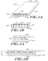
- a cold plate 100 for liquid cooling of electronic components is illustrated in Figs. 1(a) and 1(b).
- the cold plate 100 includes a top surface 120 and a bottom surface 130 that are substantially parallel and contiguously connected by rounded corners 122 and 124.
- a plurality of fins 110 extend substantially perpendicular between the top and bottom surfaces to form a plurality of channels 140 through the length of the cold plate 100.
- the fins may extend straight or spiral/twist down the length of the tube in this embodiment.
- the cold plate 100 copper, aluminum or other like materials or compositions can be extruded into flattened tubes containing the plurality of fins 110. Because the cold plate 100 is formed from copper tubes, or other formable conductors, in an extrusion process, the manufacturing process is very cost effective. Also, the cold plate 100 of the present embodiment will have a thermal performance similar to cold plates formed of a vacuum-brazed process because the fins 110 are very thin walls. However, the cold plate 100 of the present embodiment is manufactured at a fraction of the cost of the vacuum-brazed cold plates. The flattened tube structure of the cold plate 100 is also extremely strong and can sustain internal pressures on the order of approximately 1000 psi or more.
- the internal fins 110 act as spacers which prevents the tube from buckling and the passage from collapsing.
- the cold plate 100 may be bent and shaped for placement in small and tight cooling areas. For instance, the cold plate 100 may be bent at a sharp radius and placed in an area near a motor to cool electrical components.
- header tubes 150 and 152 are connected as manifolds in the openings to the ends of the cold plate 100 as illustrated in the examples of Figs. 2(a) and 2(b).
- the header tubes 150 and 152 are attached by either gluing, soldering, brazing, welding or other known attaching techniques.
- one cold plate 100 is connected between the header tubes 150 and 152 and in the embodiment of Fig. 2(b), five cold plates 100 1 -100 5 are connected between the header tubes 150 and 152 with any more number possible.
- electrical components are directly attached to the top surface of the cold plate 100 by glue, epoxy or other known adhesives.
- screw attachments 170 are attached to the top surface of the cold plate 100 as illustrated in Fig. 3 so that the electrical components can be conveniently attached and removed as necessary.
- the screw attachments 170 are stud welded directly to the top surface of the cold plate 100 so that the electrical components have a receptacle for attachment and removal.
- the screw attachments 170 may be of aluminum, copper or other like materials and compositions.
- the cold plate 100 may be formed of flattened tubes made in a variety of different widths. For instance, flattened tubes of widths ranging from 1.6 inches to 2.0 inches have been manufactured and shown to be of sufficient widths for many applications. However, it is possible to produce the cold plates 100 from flattened tubes having widths of 6 inches and greater if necessary.
- the flattened tubes may be made from aluminum, copper, and like metals and composites.
- copper tubing is preferred over aluminum because of its advantageous characteristics such as better thermal conductivity than aluminum.
- copper is a more suitable material when using water as a cooling fluid because aluminum corrodes in the presence of water.
- well known and commercially available corrosion inhibitors such as ethylene glycol mixtures, must be added to the water.
- well known and commercially available anticorrosion fluids such as hi-dielectric fluids, are used in place of the water/corrosion inhibitor mixtures in place of water.
- the fins 110 may be spaced further apart to provide wider channels 140 because water provides excellent heat transfer characteristics.
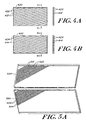
- FIGs. 4(a) and 4(b) illustrate an example of a top section and a bottom section 420 and 430 respectively of a cold plate having angled fins 412 and 414 according to an embodiment of the present invention. When the top and bottom sections are superimposed on one another, the angled fins cross one another and provide angled fluid flow paths through channels 422 and 424 which greatly enhances the heat transfer.
- Fig. 5(a) illustrates the geometry formed of the angled fins 512 and 514 on the top and bottom sections 520 and 530 respectively and Fig.
- FIG. 5(b) illustrates an isometric view of the internal passages of the cold plate according to the present embodiment.
- the thickness and length of the fins as well as the intersection angle of the fins may vary based on the desired application of the cold plate.
- the walls of the fins may be easily tailored to be thin or thick, and spaced closely or widely depending on the particular application.
- the process used to produce the pattern of flow channels comprises post-processing a copper or other tube 600 with straight spiral fins 610 extruded down the length of the internal diameter.
- An exemplary cross section of the geometry of the copper tube 600 prior to any post-processing is illustrated in Fig. 6.
- the post-processing procedure includes the step of modifying the external shape for the copper tube 600 from its original diameter to a flat tube such that the fins 610 are in contact with each other at the crossing points. Such a modification can be achieved by extruding the tube 600 through one or more dies and/or by use of a clamping form 604 causing the tube 600 to flatten.
- a variety of methods for attaching the fins 610 to one another can be used to improve the pressure resistance of the flattened tube for the resulting cold plate.
- the attaching methods may include soldering, brazing and welding the fins 610.
- Figs. 7 (a) and 7(b) illustrates a completed cold plate system 700 according to an embodiment of the present invention with an inlet tube 720 and an outlet tube 730 brazed into opposite ends of the flattened tube 710 to provide a system for allowing the cooling liquid to flow in and out of the channels of the flattened tube 710.
- the cold plate may be also used for two phase fluid flow according to another embodiment of the present invention.
- refrigerants such as R134a
Landscapes
- Physics & Mathematics (AREA)
- Thermal Sciences (AREA)
- Engineering & Computer Science (AREA)
- Microelectronics & Electronic Packaging (AREA)
- Cooling Or The Like Of Semiconductors Or Solid State Devices (AREA)
- Cooling Or The Like Of Electrical Apparatus (AREA)
Claims (21)
- Plaque froide (100) pour des composants électriques à refroidissement liquide, comprenant :un tube aplati formé d'un tube extrudé circulaire de façon à avoir une surface supérieure (120) et une surface inférieure (130) qui soient substantiellement parallèles et raccordées de façon contiguë par des coins arrondis (122, 124) et définissant un espace intérieur, ledit tube extrudé circulaire incluant,une pluralité d'ailettes (110) s'étendant dans ledit espace intérieur de ses parois intérieures de façon à former une pluralité de canaux (140) dans ledit tube aplati entre lesdites ailettes pour définir un passage de liquide de refroidissement entre elles,ladite pluralité d'ailettes (412, 414) comprenant des parties d'ailette extrudée espacées autour de ladite paroi intérieure dudit tube aplati.
- Plaque froide selon la revendication 1, comprenant en outre un premier et un deuxième tube extérieur (150, 152) raccordés à des arêtes opposées dudit tube aplati qui se raccordent à ladite pluralité de canaux (140) et procurent une admission dudit liquide de refroidissement audit premier tube extérieur et une évacuation dudit liquide de refroidissement après qu'il soit passé au travers desdits canaux dudit deuxième tube extérieur.
- Plaque froide selon la revendication 1, dans laquelle ledit tube aplati s'étend dans une direction et lesdites ailettes (110) s'étendent parallèlement à ladite direction.
- Plaque froide selon la revendication 1, dans laquelle ledit tube aplati s'étend dans une direction et lesdites ailettes (412, 414) s'étendent selon un angle prédéterminé par rapport à ladite direction.
- Plaque froide selon la revendication 1, dans laquelle lesdites ailettes (512) associées à ladite surface supérieure (520) s'étendent selon un angle par rapport aux ailettes (514) associées à ladite surface inférieure (530) formant une pluralité de points d'intersection pour former un chemin tortueux d'écoulement de fluide.
- Plaque froide selon la revendication 1, dans laquelle ledit tube aplati comprend du cuivre.
- Plaque froide selon la revendication 1, dans laquelle ledit liquide de refroidissement comprend de l'eau.
- Plaque froide selon la revendication 2, dans laquelle une pluralité desdits tubes aplatis est raccordée au dit premier et deuxième tube extérieur (150, 152).
- Plaque froide selon l'une quelconque des revendications précédentes, dans laquelle le tube aplati comprend une pluralité de montures de fixation (170) s'étendant à partir de celui-ci pour recevoir les composants électriques.
- Plaque froide selon la revendication 9, dans laquelle chaque monture de la pluralité de montures de fixation (170) comprend une fixation respective par vis, la fixation respective par vis autorisant au moins l'un des composants électriques à pouvoir être attaché à celle-ci et d'être amovible de celle-ci.
- Plaque froide selon la revendication 10, dans laquelle chaque fixation par vis est soudée en tant que goujon fileté directement à la surface supérieure dudit tube aplati.
- Plaque froide selon les revendications 10 ou 11, dans laquelle chaque fixation par vis comprend du cuivre.
- Plaque froide selon les revendications 10 ou 11, dans laquelle chaque fixation par vis comprend de l'aluminium.
- Méthode de formation d'un système de plaque froide pour des composants électriques à refroidissement liquide, comprenant les étapes de :(a) extruder du métal en un tube circulaire comprenant une pluralité d'ailettes (110) s'étendant de la surface intérieure dudit tube, lesdites ailettes (110) étant espacées également et d'une hauteur prédéterminée ;(b) aplatir ledit tube de façon à ce qu'une surface supérieure (120) et une surface inférieure (130) soient substantiellement parallèles et raccordées de façon contiguë par des coins arrondis et que lesdites ailettes s'étendent dans un intérieur entre lesdites surfaces supérieure et inférieure ; et(c) dans laquelle ladite étape d'extrusion comprend l'extension du tube aplati pour comprendre des parties d'ailette espacées autour de ladite paroi intérieure dudit tube aplati et dans laquelle lesdites ailettes de surfaces opposées entrent en contact les unes avec les autres pour former une pluralité de canaux (140).
- Méthode selon la revendication 14, comprenant en outre l'étape de raccorder le premier et le deuxième tube extérieur (150, 152) à des arêtes dudit tube aplati pour procurer une admission d'un liquide de refroidissement aux dits canaux audit premier tube extérieur et une évacuation dudit liquide de refroidissement audit deuxième tube extérieur.
- Méthode selon la revendication 14, dans laquelle ledit tube aplati s'étend dans une direction et lesdites ailettes (110) s'étendent parallèlement à ladite direction.
- Méthode selon la revendication 14, dans laquelle ledit tube aplati s'étend dans une direction et lesdites ailettes (412, 414) s'étendent selon un angle prédéterminé par rapport à ladite direction.
- Méthode selon la revendication 14, dans laquelle lesdites ailettes (512) associées à ladite surface supérieure (520) s'étendent selon un angle par rapport aux ailettes associées à ladite surface inférieure (530) formant une pluralité de points d'intersection pour former un chemin tortueux d'écoulement de fluide.
- Méthode selon la revendication 14, dans laquelle ledit tube aplati est extrudé à partir de cuivre à ladite étape (a).
- Méthode selon la revendication 15, dans laquelle ledit liquide de refroidissement comprend de l'eau.
- Méthode selon la revendication 15, comprenant en outre l'étape de raccorder une pluralité desdits tubes aplatis entre lesdits premier et deuxième tube extérieur (150, 152).
Applications Claiming Priority (4)
| Application Number | Priority Date | Filing Date | Title |
|---|---|---|---|
| US30547901P | 2001-07-13 | 2001-07-13 | |
| US305479P | 2001-07-13 | ||
| US33959301P | 2001-12-11 | 2001-12-11 | |
| US339593 | 2001-12-11 |
Publications (3)
| Publication Number | Publication Date |
|---|---|
| EP1276362A2 EP1276362A2 (fr) | 2003-01-15 |
| EP1276362A3 EP1276362A3 (fr) | 2003-07-16 |
| EP1276362B1 true EP1276362B1 (fr) | 2006-02-01 |
Family
ID=26974623
Family Applications (1)
| Application Number | Title | Priority Date | Filing Date |
|---|---|---|---|
| EP02015796A Expired - Lifetime EP1276362B1 (fr) | 2001-07-13 | 2002-07-15 | Plaque froide en forme de tube aplati pour le refroidissement liquide de composants électriques |
Country Status (3)
| Country | Link |
|---|---|
| US (1) | US7178586B2 (fr) |
| EP (1) | EP1276362B1 (fr) |
| DE (1) | DE60208953T2 (fr) |
Families Citing this family (34)
| Publication number | Priority date | Publication date | Assignee | Title |
|---|---|---|---|---|
| DE102004019382B4 (de) * | 2004-04-19 | 2006-05-24 | Rittal Gmbh & Co. Kg | Kühlanordnung mit einer Montageplatte für elektronische Bauteile |
| US7135863B2 (en) * | 2004-09-30 | 2006-11-14 | General Electric Company | Thermal management system and method for MRI gradient coil |
| US7182128B2 (en) * | 2005-03-09 | 2007-02-27 | Visteon Global Technologies, Inc. | Heat exchanger tube having strengthening deformations |
| US20060288602A1 (en) * | 2005-06-04 | 2006-12-28 | Lg Electronics Inc. | Heat exchanger for dryer and condensing type dryer using the same |
| DE102006034800B4 (de) * | 2006-07-27 | 2010-04-08 | Siemens Ag | Verfahren zur Herstellung einer Kühleinrichtung für eine Gradientenspule, Kühleinrichtung für eine Gradientenspule, sowie Gradientenspule umfassend solche Kühleinrichtungen |
| EP1916884B1 (fr) * | 2006-10-27 | 2011-04-06 | Agie Charmilles SA | Unité de carte de circuit imprimé et procédé de sa production |
| US7548424B2 (en) * | 2007-03-12 | 2009-06-16 | Raytheon Company | Distributed transmit/receive integrated microwave module chip level cooling system |
| US20100132930A1 (en) * | 2007-05-02 | 2010-06-03 | Creare, Inc. | Flexible Heat/Mass Exchanger |
| DE102007027369A1 (de) * | 2007-06-11 | 2008-12-18 | Mingatec Gmbh | Wärmeübertragungskanal für Wärmeübertrager |
| US7495916B2 (en) * | 2007-06-19 | 2009-02-24 | Honeywell International Inc. | Low cost cold plate with film adhesive |
| TW201036527A (en) * | 2009-03-19 | 2010-10-01 | Acbel Polytech Inc | Large-area liquid-cooled heat-dissipation device |
| US8045329B2 (en) * | 2009-04-29 | 2011-10-25 | Raytheon Company | Thermal dissipation mechanism for an antenna |
| US8157169B2 (en) * | 2009-11-02 | 2012-04-17 | Raytheon Company | Projectile targeting system |
| US8844472B2 (en) * | 2009-12-22 | 2014-09-30 | Lochinvar, Llc | Fire tube heater |
| US20110232877A1 (en) * | 2010-03-23 | 2011-09-29 | Celsia Technologies Taiwan, Inc. | Compact vapor chamber and heat-dissipating module having the same |
| US10531594B2 (en) | 2010-07-28 | 2020-01-07 | Wieland Microcool, Llc | Method of producing a liquid cooled coldplate |
| US9795057B2 (en) | 2010-07-28 | 2017-10-17 | Wolverine Tube, Inc. | Method of producing a liquid cooled coldplate |
| US20130068433A1 (en) * | 2011-03-17 | 2013-03-21 | Shreekanth Murthy Muthigi | Heat exchanger |
| DE202011051021U1 (de) * | 2011-08-18 | 2012-11-20 | IGH Ingenieurbüro Gallatz & Hirsch GmbH | Konduktionstragkörper für ein Heiz- oder Kühlpaneel |
| USD763417S1 (en) * | 2012-08-02 | 2016-08-09 | Mitsubishi Electric Corporation | Heat exchanger tube |
| US9095078B2 (en) | 2012-08-16 | 2015-07-28 | International Business Machines Corporation | Actively controlling coolant-cooled cold plate configuration |
| US20140374057A1 (en) * | 2013-06-19 | 2014-12-25 | Treasure Unicorn Limited | Heat dissipation device |
| US9439325B2 (en) | 2013-10-21 | 2016-09-06 | International Business Machines Corporation | Coolant-cooled heat sink configured for accelerating coolant flow |
| US9357674B2 (en) | 2013-12-18 | 2016-05-31 | International Business Machines Corporation | Liquid-cooling apparatus with integrated coolant filter |
| US20160025422A1 (en) * | 2014-07-22 | 2016-01-28 | Hamilton Sundstrand Space Systems International, Inc. | Heat transfer plate |
| USD749713S1 (en) | 2014-07-31 | 2016-02-16 | Innovative Medical Equipment, Llc | Heat exchanger |
| CN104384883A (zh) * | 2014-11-19 | 2015-03-04 | 柳州凯通机械有限公司 | 冷却器管板的加工方法 |
| WO2016187131A1 (fr) * | 2015-05-15 | 2016-11-24 | Wolverine Tube, Inc. | Plaque de refroidissement refroidie par liquide |
| US10584923B2 (en) | 2017-12-07 | 2020-03-10 | General Electric Company | Systems and methods for heat exchanger tubes having internal flow features |
| US10761162B2 (en) | 2018-09-18 | 2020-09-01 | General Electric Company | Gradient coil cooling systems |
| US11686539B2 (en) | 2020-03-09 | 2023-06-27 | Raytheon Company | Coldplate with heat transfer module |
| CN114071945A (zh) | 2020-08-06 | 2022-02-18 | 台达电子工业股份有限公司 | 液冷导管 |
| CN112152119B (zh) * | 2020-09-22 | 2022-09-13 | 国网山东省电力公司烟台供电公司 | 一种封闭式电力配电柜高频防老化降温装置 |
| US12188731B2 (en) | 2020-09-25 | 2025-01-07 | Acleap Power Inc. | Systems and methods for thermal management using matrix coldplates |
Family Cites Families (16)
| Publication number | Priority date | Publication date | Assignee | Title |
|---|---|---|---|---|
| GB684830A (en) * | 1951-10-01 | 1952-12-24 | Herman Lodding | Heat exchange apparatus |
| EP0132237A3 (fr) * | 1983-06-30 | 1986-02-05 | Renato Ferroni | Elément pour l'échange de chaleur entre fluides et radiateur fabriqué avec le dit élément |
| NO155069C (no) * | 1984-10-17 | 1987-02-04 | Norsk Hydro As | Hulprofil, dens anvendelse i varmevekslere og fremgangsmaate ved fremstilling. |
| US5102032A (en) * | 1989-09-12 | 1992-04-07 | Modine Manufacturing Company | Finned assembly for heat exchangers |
| US5305945A (en) * | 1989-09-12 | 1994-04-26 | Modine Manufacturing Co. | Finned assembly for heat exchangers |
| JPH04217791A (ja) * | 1990-12-18 | 1992-08-07 | Showa Alum Corp | 細線構造のフィンを有する熱交換器 |
| US5317805A (en) * | 1992-04-28 | 1994-06-07 | Minnesota Mining And Manufacturing Company | Method of making microchanneled heat exchangers utilizing sacrificial cores |
| FR2751473B1 (fr) * | 1993-02-23 | 1998-12-18 | Thomson Csf | Structure d'antenne a modules actifs |
| US5829516A (en) | 1993-12-15 | 1998-11-03 | Aavid Thermal Products, Inc. | Liquid cooled heat sink for cooling electronic components |
| JPH07180984A (ja) * | 1993-12-21 | 1995-07-18 | Sanden Corp | 熱交換器及びその製造方法 |
| US5453911A (en) * | 1994-02-17 | 1995-09-26 | General Motors Corporation | Device for cooling power electronics |
| US5826646A (en) * | 1995-10-26 | 1998-10-27 | Heatcraft Inc. | Flat-tubed heat exchanger |
| FR2748800A1 (fr) * | 1996-05-15 | 1997-11-21 | Ferraz | Echangeur de chaleur pour composants electroniques et autres appareillages electro-techniques |
| US5920457A (en) | 1996-09-25 | 1999-07-06 | International Business Machines Corporation | Apparatus for cooling electronic devices using a flexible coolant conduit |
| US5983997A (en) * | 1996-10-17 | 1999-11-16 | Brazonics, Inc. | Cold plate having uniform pressure drop and uniform flow rate |
| DE19813532C1 (de) * | 1998-03-26 | 1999-09-30 | Siemens Ag | Steuergerät mit Flüssigkeitskühlung |
-
2002
- 2002-07-15 DE DE60208953T patent/DE60208953T2/de not_active Expired - Lifetime
- 2002-07-15 US US10/195,840 patent/US7178586B2/en not_active Expired - Lifetime
- 2002-07-15 EP EP02015796A patent/EP1276362B1/fr not_active Expired - Lifetime
Also Published As
| Publication number | Publication date |
|---|---|
| EP1276362A3 (fr) | 2003-07-16 |
| US20030010485A1 (en) | 2003-01-16 |
| DE60208953D1 (de) | 2006-04-13 |
| DE60208953T2 (de) | 2006-09-21 |
| US7178586B2 (en) | 2007-02-20 |
| EP1276362A2 (fr) | 2003-01-15 |
Similar Documents
| Publication | Publication Date | Title |
|---|---|---|
| EP1276362B1 (fr) | Plaque froide en forme de tube aplati pour le refroidissement liquide de composants électriques | |
| US5040596A (en) | Heat exchanger core | |
| US6935409B1 (en) | Cooling apparatus having low profile extrusion | |
| US6729389B2 (en) | Heat transfer apparatus with zigzag passage | |
| US7198096B2 (en) | Stacked low profile cooling system and method for making same | |
| EP0858578B1 (fr) | Dissipateur de chaleur a refroidissement par liquide permettant de refroidir des composants electroniques | |
| EP2031332B1 (fr) | Échangeur de chaleur pour des composants d'électronique de puissance | |
| US8621875B2 (en) | Method of removing heat utilizing geometrically reoriented low-profile phase plane heat pipes | |
| EP1387139A2 (fr) | Caloduc et échangeur de chaleur avec caloducs | |
| US20090294105A1 (en) | Selectively Grooved Cold Plate for Electronics Cooling | |
| US6688380B2 (en) | Corrugated fin heat exchanger and method of manufacture | |
| US6354002B1 (en) | Method of making a thick, low cost liquid heat transfer plate with vertically aligned fluid channels | |
| JP3641422B2 (ja) | 冷却板の製造方法 | |
| US20090236083A1 (en) | Heat Exchanger for Small Components | |
| WO1995017765A2 (fr) | Dissipateur thermique a refroidissement liquide utilise dans le refroidissement de composants electroniques | |
| CN111504111B (zh) | 蒸发器和制造方法 | |
| JP2011003708A (ja) | コルゲート状放熱ユニットを用いた熱交換器 | |
| JP3010602U (ja) | 電子部品冷却器 | |
| JP7650982B2 (ja) | 熱交換器及び熱交換器の製造方法 | |
| US6883598B2 (en) | Cooling element for a heat exchanger | |
| JP2004335846A (ja) | 熱交換器 | |
| JPH0983164A (ja) | ヒートシンクおよびその製造方法 | |
| CN1282285C (zh) | 背冷式高功率半导体激光器微通道热沉结构及制备方法 | |
| WO2010072221A2 (fr) | Dispositif de refroidissement comprenant un tuyau plat courbé et procédé de fabrication associé | |
| KR200289452Y1 (ko) | 다수의 버링 튜브가 일체로 형성된 평판형 방열휜을이용한 열교환기 |
Legal Events
| Date | Code | Title | Description |
|---|---|---|---|
| PUAI | Public reference made under article 153(3) epc to a published international application that has entered the european phase |
Free format text: ORIGINAL CODE: 0009012 |
|
| AK | Designated contracting states |
Kind code of ref document: A2 Designated state(s): AT BE BG CH CY CZ DE DK EE ES FI FR GB GR IE IT LI LU MC NL PT SE SK TR |
|
| AX | Request for extension of the european patent |
Free format text: AL;LT;LV;MK;RO;SI |
|
| PUAL | Search report despatched |
Free format text: ORIGINAL CODE: 0009013 |
|
| AK | Designated contracting states |
Designated state(s): AT BE BG CH CY CZ DE DK EE ES FI FR GB GR IE IT LI LU MC NL PT SE SK TR |
|
| AX | Request for extension of the european patent |
Extension state: AL LT LV MK RO SI |
|
| 17P | Request for examination filed |
Effective date: 20040109 |
|
| AKX | Designation fees paid |
Designated state(s): DE FR GB IT |
|
| 17Q | First examination report despatched |
Effective date: 20041115 |
|
| GRAP | Despatch of communication of intention to grant a patent |
Free format text: ORIGINAL CODE: EPIDOSNIGR1 |
|
| GRAS | Grant fee paid |
Free format text: ORIGINAL CODE: EPIDOSNIGR3 |
|
| GRAA | (expected) grant |
Free format text: ORIGINAL CODE: 0009210 |
|
| AK | Designated contracting states |
Kind code of ref document: B1 Designated state(s): DE FR GB IT |
|
| PG25 | Lapsed in a contracting state [announced via postgrant information from national office to epo] |
Ref country code: IT Free format text: LAPSE BECAUSE OF FAILURE TO SUBMIT A TRANSLATION OF THE DESCRIPTION OR TO PAY THE FEE WITHIN THE PRESCRIBED TIME-LIMIT;WARNING: LAPSES OF ITALIAN PATENTS WITH EFFECTIVE DATE BEFORE 2007 MAY HAVE OCCURRED AT ANY TIME BEFORE 2007. THE CORRECT EFFECTIVE DATE MAY BE DIFFERENT FROM THE ONE RECORDED. Effective date: 20060201 |
|
| REG | Reference to a national code |
Ref country code: GB Ref legal event code: FG4D |
|
| REF | Corresponds to: |
Ref document number: 60208953 Country of ref document: DE Date of ref document: 20060413 Kind code of ref document: P |
|
| PG25 | Lapsed in a contracting state [announced via postgrant information from national office to epo] |
Ref country code: GB Free format text: LAPSE BECAUSE OF NON-PAYMENT OF DUE FEES Effective date: 20060715 |
|
| PLBE | No opposition filed within time limit |
Free format text: ORIGINAL CODE: 0009261 |
|
| STAA | Information on the status of an ep patent application or granted ep patent |
Free format text: STATUS: NO OPPOSITION FILED WITHIN TIME LIMIT |
|
| 26N | No opposition filed |
Effective date: 20061103 |
|
| EN | Fr: translation not filed | ||
| GBPC | Gb: european patent ceased through non-payment of renewal fee |
Effective date: 20060715 |
|
| PG25 | Lapsed in a contracting state [announced via postgrant information from national office to epo] |
Ref country code: FR Free format text: LAPSE BECAUSE OF FAILURE TO SUBMIT A TRANSLATION OF THE DESCRIPTION OR TO PAY THE FEE WITHIN THE PRESCRIBED TIME-LIMIT Effective date: 20070323 |
|
| PG25 | Lapsed in a contracting state [announced via postgrant information from national office to epo] |
Ref country code: FR Free format text: LAPSE BECAUSE OF FAILURE TO SUBMIT A TRANSLATION OF THE DESCRIPTION OR TO PAY THE FEE WITHIN THE PRESCRIBED TIME-LIMIT Effective date: 20060201 |
|
| PGFP | Annual fee paid to national office [announced via postgrant information from national office to epo] |
Ref country code: DE Payment date: 20220131 Year of fee payment: 20 |
|
| REG | Reference to a national code |
Ref country code: DE Ref legal event code: R071 Ref document number: 60208953 Country of ref document: DE |