EP1387139A2 - Caloduc et échangeur de chaleur avec caloducs - Google Patents
Caloduc et échangeur de chaleur avec caloducs Download PDFInfo
- Publication number
- EP1387139A2 EP1387139A2 EP03016632A EP03016632A EP1387139A2 EP 1387139 A2 EP1387139 A2 EP 1387139A2 EP 03016632 A EP03016632 A EP 03016632A EP 03016632 A EP03016632 A EP 03016632A EP 1387139 A2 EP1387139 A2 EP 1387139A2
- Authority
- EP
- European Patent Office
- Prior art keywords
- tank
- pipes
- heat pipe
- heat exchanger
- type heat
- Prior art date
- Legal status (The legal status is an assumption and is not a legal conclusion. Google has not performed a legal analysis and makes no representation as to the accuracy of the status listed.)
- Granted
Links
Images



Classifications
-
- F—MECHANICAL ENGINEERING; LIGHTING; HEATING; WEAPONS; BLASTING
- F28—HEAT EXCHANGE IN GENERAL
- F28D—HEAT-EXCHANGE APPARATUS, NOT PROVIDED FOR IN ANOTHER SUBCLASS, IN WHICH THE HEAT-EXCHANGE MEDIA DO NOT COME INTO DIRECT CONTACT
- F28D15/00—Heat-exchange apparatus with the intermediate heat-transfer medium in closed tubes passing into or through the conduit walls ; Heat-exchange apparatus employing intermediate heat-transfer medium or bodies
- F28D15/02—Heat-exchange apparatus with the intermediate heat-transfer medium in closed tubes passing into or through the conduit walls ; Heat-exchange apparatus employing intermediate heat-transfer medium or bodies in which the medium condenses and evaporates, e.g. heat pipes
-
- F—MECHANICAL ENGINEERING; LIGHTING; HEATING; WEAPONS; BLASTING
- F28—HEAT EXCHANGE IN GENERAL
- F28D—HEAT-EXCHANGE APPARATUS, NOT PROVIDED FOR IN ANOTHER SUBCLASS, IN WHICH THE HEAT-EXCHANGE MEDIA DO NOT COME INTO DIRECT CONTACT
- F28D15/00—Heat-exchange apparatus with the intermediate heat-transfer medium in closed tubes passing into or through the conduit walls ; Heat-exchange apparatus employing intermediate heat-transfer medium or bodies
- F28D15/02—Heat-exchange apparatus with the intermediate heat-transfer medium in closed tubes passing into or through the conduit walls ; Heat-exchange apparatus employing intermediate heat-transfer medium or bodies in which the medium condenses and evaporates, e.g. heat pipes
- F28D15/0233—Heat-exchange apparatus with the intermediate heat-transfer medium in closed tubes passing into or through the conduit walls ; Heat-exchange apparatus employing intermediate heat-transfer medium or bodies in which the medium condenses and evaporates, e.g. heat pipes the conduits having a particular shape, e.g. non-circular cross-section, annular
-
- F—MECHANICAL ENGINEERING; LIGHTING; HEATING; WEAPONS; BLASTING
- F28—HEAT EXCHANGE IN GENERAL
- F28D—HEAT-EXCHANGE APPARATUS, NOT PROVIDED FOR IN ANOTHER SUBCLASS, IN WHICH THE HEAT-EXCHANGE MEDIA DO NOT COME INTO DIRECT CONTACT
- F28D15/00—Heat-exchange apparatus with the intermediate heat-transfer medium in closed tubes passing into or through the conduit walls ; Heat-exchange apparatus employing intermediate heat-transfer medium or bodies
- F28D15/02—Heat-exchange apparatus with the intermediate heat-transfer medium in closed tubes passing into or through the conduit walls ; Heat-exchange apparatus employing intermediate heat-transfer medium or bodies in which the medium condenses and evaporates, e.g. heat pipes
- F28D15/0266—Heat-exchange apparatus with the intermediate heat-transfer medium in closed tubes passing into or through the conduit walls ; Heat-exchange apparatus employing intermediate heat-transfer medium or bodies in which the medium condenses and evaporates, e.g. heat pipes with separate evaporating and condensing chambers connected by at least one conduit; Loop-type heat pipes; with multiple or common evaporating or condensing chambers
-
- F—MECHANICAL ENGINEERING; LIGHTING; HEATING; WEAPONS; BLASTING
- F28—HEAT EXCHANGE IN GENERAL
- F28D—HEAT-EXCHANGE APPARATUS, NOT PROVIDED FOR IN ANOTHER SUBCLASS, IN WHICH THE HEAT-EXCHANGE MEDIA DO NOT COME INTO DIRECT CONTACT
- F28D15/00—Heat-exchange apparatus with the intermediate heat-transfer medium in closed tubes passing into or through the conduit walls ; Heat-exchange apparatus employing intermediate heat-transfer medium or bodies
- F28D15/02—Heat-exchange apparatus with the intermediate heat-transfer medium in closed tubes passing into or through the conduit walls ; Heat-exchange apparatus employing intermediate heat-transfer medium or bodies in which the medium condenses and evaporates, e.g. heat pipes
- F28D15/0275—Arrangements for coupling heat-pipes together or with other structures, e.g. with base blocks; Heat pipe cores
-
- F—MECHANICAL ENGINEERING; LIGHTING; HEATING; WEAPONS; BLASTING
- F28—HEAT EXCHANGE IN GENERAL
- F28F—DETAILS OF HEAT-EXCHANGE AND HEAT-TRANSFER APPARATUS, OF GENERAL APPLICATION
- F28F1/00—Tubular elements; Assemblies of tubular elements
- F28F1/10—Tubular elements and assemblies thereof with means for increasing heat-transfer area, e.g. with fins, with projections, with recesses
- F28F1/12—Tubular elements and assemblies thereof with means for increasing heat-transfer area, e.g. with fins, with projections, with recesses the means being only outside the tubular element
- F28F1/24—Tubular elements and assemblies thereof with means for increasing heat-transfer area, e.g. with fins, with projections, with recesses the means being only outside the tubular element and extending transversely
- F28F1/32—Tubular elements and assemblies thereof with means for increasing heat-transfer area, e.g. with fins, with projections, with recesses the means being only outside the tubular element and extending transversely the means having portions engaging further tubular elements
-
- F—MECHANICAL ENGINEERING; LIGHTING; HEATING; WEAPONS; BLASTING
- F28—HEAT EXCHANGE IN GENERAL
- F28F—DETAILS OF HEAT-EXCHANGE AND HEAT-TRANSFER APPARATUS, OF GENERAL APPLICATION
- F28F1/00—Tubular elements; Assemblies of tubular elements
- F28F1/10—Tubular elements and assemblies thereof with means for increasing heat-transfer area, e.g. with fins, with projections, with recesses
- F28F1/40—Tubular elements and assemblies thereof with means for increasing heat-transfer area, e.g. with fins, with projections, with recesses the means being only inside the tubular element
-
- H—ELECTRICITY
- H10—SEMICONDUCTOR DEVICES; ELECTRIC SOLID-STATE DEVICES NOT OTHERWISE PROVIDED FOR
- H10W—GENERIC PACKAGES, INTERCONNECTIONS, CONNECTORS OR OTHER CONSTRUCTIONAL DETAILS OF DEVICES COVERED BY CLASS H10
- H10W40/00—Arrangements for thermal protection or thermal control
- H10W40/70—Fillings or auxiliary members in containers or in encapsulations for thermal protection or control
- H10W40/73—Fillings or auxiliary members in containers or in encapsulations for thermal protection or control for cooling by change of state
-
- F—MECHANICAL ENGINEERING; LIGHTING; HEATING; WEAPONS; BLASTING
- F28—HEAT EXCHANGE IN GENERAL
- F28D—HEAT-EXCHANGE APPARATUS, NOT PROVIDED FOR IN ANOTHER SUBCLASS, IN WHICH THE HEAT-EXCHANGE MEDIA DO NOT COME INTO DIRECT CONTACT
- F28D21/00—Heat-exchange apparatus not covered by any of the groups F28D1/00 - F28D20/00
- F28D2021/0019—Other heat exchangers for particular applications; Heat exchange systems not otherwise provided for
- F28D2021/0028—Other heat exchangers for particular applications; Heat exchange systems not otherwise provided for for cooling heat generating elements, e.g. for cooling electronic components or electric devices
- F28D2021/0031—Radiators for recooling a coolant of cooling systems
-
- F—MECHANICAL ENGINEERING; LIGHTING; HEATING; WEAPONS; BLASTING
- F28—HEAT EXCHANGE IN GENERAL
- F28F—DETAILS OF HEAT-EXCHANGE AND HEAT-TRANSFER APPARATUS, OF GENERAL APPLICATION
- F28F2275/00—Fastening; Joining
- F28F2275/04—Fastening; Joining by brazing
-
- F—MECHANICAL ENGINEERING; LIGHTING; HEATING; WEAPONS; BLASTING
- F28—HEAT EXCHANGE IN GENERAL
- F28F—DETAILS OF HEAT-EXCHANGE AND HEAT-TRANSFER APPARATUS, OF GENERAL APPLICATION
- F28F2275/00—Fastening; Joining
- F28F2275/20—Fastening; Joining with threaded elements
Definitions
- the present invention relates to a heat pipe type heat exchanger for use in cooling, for example, semiconductor devices and the like.
- Heat pipe type heat exchangers are widely used to cool control devices that utilize a semiconductor device such as a power transistor or vehicle-mounted transistor, or thyristor.
- a conventional heat pipe type heat exchanger 20 is made up of a heat receiver block 21 that receives heat from an exothermic body, a plurality of heat pipes 13 having their base portions embedded in the heat receiver block 21 at a predetermined spacing, and an intermediate partition plate 18, fins 24 and a guide 17 that are assembled in sequence to the exposed portions of the heat pipes 13 from the base portions toward the top.
- the fins 24 dissipate heat from the heat pipes 13, and the intermediate partition plate 18 serves to divide the casing containing a semiconductor device (not shown) such as a thyristor and the like and the outside, while at the same time serving, along with the guide 17, to fasten the heat pipes 13 to one another.
- the heat receiver block 21 and the fins 24 are formed from a material with good thermal conductivity such as copper, aluminum or the like.
- Such a heat pipe type heat exchanger is disclosed for example in Japanese Patent Application Unexamined Publication No. Hei 8-210789 (Fig. 4) and has features such as light weight, compactness, low maintenance and the like.
- Heat exchangers are generally used based on required capacities, i.e., heat sinks for a small capacity, heat pipes for an intermediate capacity, and thermosyphon type heat exchangers for a large capacity.
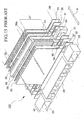
- Fig. 15 Shown in Fig. 15 is an example of a thermosyphon type heat exchanger.
- Fig. 15 is a partial exploded perspective view of a thermosyphon type heat exchanger 100, with components shown exploded.
- the thermosyphon type heat exchanger 100 roughly has a shape of two rectangular parallelepipeds placed one on the other and is comprised of a substantially rectangular parallelepiped condenser section 27, a substantially rectangular parallelepiped tank section 30 disposed below the condenser section 27, and a substantially rectangular parallelepiped front apron section 40 extending forwardly in the back-and-forth direction indicated by a double-headed arrow A.
- the condenser section 27 is constituted by a partition plate 31, a combination of fins 41 and a header 50, a partition plate 31, a frame body 26 and a partition plate 31 laminated in this order in the back-and-forth direction indicated by the double-headed arrow A and joined together, with an end plate 37 joined to the front end.
- the condenser section 27 thus includes many rectangular spaces 26a defined by the frame body 26 and the two partition plates 31,31 that hold the frame body 26 therebetween as well as many fins 41. To increase the heat dissipation action, the fins 41 are held between the two partition walls 31,31.
- a plurality of paths that allow flow therethrough of working fluid in gaseous phase the plurality of paths being defined by a plurality of vapor paths 55 provided in the header 50, a plurality of vapor paths 35 provided in each partition plate 31, and the plurality of rectangular spaces 26a.
- the tank section 30 has therein the partition plate 31, a tank segment 25, the partition plate 31, the frame body 26 and the partition plate 31 joined together in this order in the back-and-forth direction such that working fluid paths 38 provided in the tank segment 25 align with corresponding liquid paths 34 provided in each partition plate 31, with an end plate 32 joined at the front end.
- the tank section 30 is thus formed with a plurality of liquid receivers, which partially open upwardly to receive working fluid in the liquid phase.
- An exothermic body (not shown) is connected to the underside of the tank section 30.
- the front apron section 40 is made up of an end segment 28 and two corner segments 23, 23 and is primarily used to attach the thermosyphon type heat exchanger 100.
- thermosyphon type heat exchanger is excellent in performance, but is complicated in structure as indicated in Fig. 15 and thus is costly.
- thermosyphon type heat exchanger with the conventional heat pipe type heat exchanger, which is simpler in structure than the thermosyphon type heat exchanger, many heat pipes would be required, eventually resulting in an increase in cost due to enlargement of the heat exchanger size, production difficulties and the like.
- the present invention has been made under such circumstances, and accordingly, it is an object of the present invention to provide a heat pipe unit and a heat pipe type heat exchanger which are simple in structure and easy to produce, and which have an improved thermal efficiency for its compact size.
- a heat pipe unit comprising: a tank; a plurality of pipes provided upstanding on and joined to a side of the tank to be in communication with the tank, the plurality of pipes being closed at an end thereof opposite an end where the plurality of pipes are joined to the tank; a working fluid sealed in the tank and movable between the plurality of pipes and the tank, and a plurality of fins each provided on the plurality of pipes.
- the tank comprises a pipe of circular cross section and is provided with a groove on an inner surface thereof.
- the groove has a depth of 0.01 to 0.5 mm and a pitch of 4 mm or less.
- a heat pipe type heat exchanger comprising: a tank; a plurality of pipes provided upstanding on and joined to a side of the tank to be in communication with the tank, the plurality of pipes being closed at an end thereof opposite an end where the plurality of pipes are joined to the tank; a working fluid sealed in the tank and movable between the plurality of pipes and the tank; a base block of metal having the tank embedded therein; and a plurality of fins each provided on the plurality of pipes.
- the tank comprises a pipe of circular cross section and is provided on an inner surface thereof with a groove.
- the groove has a depth of 0.01 to 0.5 mm and a pitch of 4 mm or less.
- the heat generated at a semiconductor device is transferred to the base block having good thermal conductivity, distributed uniformly inside the base block, and dissipated into the atmosphere by way of the plurality of thin pipes, making it possible to realize an improved heat exchange performance for the small size of the heat pipe type heat exchanger.
- a heat pipe type heat exchanger comprising: a plurality of tanks; a plurality of pipes provided upstanding on and joined to a side of each of the tanks to be in communication with a corresponding one of the tanks, the plurality of pipes being closed at an end thereof opposite an end where the plurality of pipes are joined to the corresponding one of the tanks; a working fluid sealed in each of the tanks and movable between the plurality of pipes and the corresponding one of the tanks; a base block of metal having the plurality of tanks embedded therein; and a plurality of fins provided on at least some of the plurality of pipes of one or more of the plurality of tanks.
- each of the plurality of tanks preferably comprises a pipe of circular cross section and is provided with a groove having a depth of 0.01 to 0.5 mm and a pitch of 4 mm or less on its inner surface. In this way, an increase is made in the contact area between the working fluid and the tanks, so as to enable easier transfer of heat from the tanks and enhancement of the heat exchange performance.
- the plurality of pipes of the plurality of tanks are arranged in a grid-like or a staggered manner in top view.
- the tank or each of the tanks is secured to the base block with mounting hardware.
- Allowing for a heat pipe type heat exchanger to be used to cool a vehicle-mounted semiconductor device it is preferable that the tank or the tanks are screwed to the base block with mounting hardware.
- a heat pipe type heat exchanger comprising: a tank; a plurality of pipes provided upstanding on and joined to a side of the tank to be in communication with the tank, the plurality of pipes being closed at an end thereof opposite an end where the plurality of pipes are joined to the tank; a working fluid sealed in the tank and movable between the plurality of pipes and the tank; a base block of metal having the tank embedded therein; and a plurality of fins each provided on the plurality of pipes, wherein the plurality of pipes are angled relative to the base block such that when the base block is mounted vertically, the plurality of pipes extend at an angle of 5 to 10° relative to a horizontal plane.
- a control device that utilizes a semiconductor device is used as an attachment for various machines and apparatuses, and as such, there are often restrictions on the location for mounting the control device as well as the direction in which to mount the control device. Consequently, to install a heat pipe type heat exchanger, the base block having the tank embedded therein must often be mounted vertically, with the pipes preferably extending sideways at an angle of 5 to 10° relative to the horizontal plane. The inclination of the pipes is to make it easier for the working fluid inside the pipes to flow into the tank.
- Fig. 1 is a perspective view of a heat pipe unit and a heat pipe type heat exchanger according to a first embodiment of the present invention.
- a heat pipe unit 10 of this embodiment is comprised of a tank 2 of circular cross section, a plurality of thin or small-diameter pipes 3 provided upstanding on the tank 2 to be in communication with the tank 2, and thin-plate fins 4 formed from a material of good thermal conductivity such as aluminum or copper, each fin arranged on the thin pipes 3 in spaced relations.
- Each fin 4 may be provided on the thin pipes 3 by, for example, providing holes in advance in each fin at predetermined positions through burring and press-fitting the fin 4 over the pipes 3 at the holes.
- each pipe 3 may be enlarged in diameter at positions for assembly thereto of the fins 4.
- the thin pipes 3 are arranged in a row with a suitable spacing therebetween.
- the tank 2 and each pipe 3 are joined together through brazing to provide an integral interior space.
- Each pipe and the tank are closed through welding at their ends to hermetically seal a working fluid such as water, (per)fluorocarbon or the like.
- the tank 2 is embedded in and integrally joined through soldering or the like to a base block 1 which is formed from a metal such as aluminum, copper or the like having a good thermal conductivity and a large thermal capacity. Consequently, heat transfer between the base block 1 and the tank 2 is effected exceedingly smoothly.
- An exothermic semiconductor device 5 is attached to a surface of the base block 1 opposite the surface where the tank 2 is buried in the base block 1.
- the heat generated at the semiconductor device 5 is transferred to and then distributed over the base block 1 so as to enter the tank 2 and cause evaporation of the working fluid inside the tank 2.
- the working fluid evaporated rises inside the thin pipes 3 such that the heat is conducted to the fins 4 and released into the atmosphere.
- the circulation of the working fluid as described above releases the heat generated at the semiconductor device 5 into the atmosphere, thereby to suppress a rise in the temperature of the semiconductor device 5 and allow the semiconductor device 5 to perform stably.
- the use of the base block 1 in the above-mentioned manner enables heat to be conducted to each thin pipe 3, thereby to enhance the cooling capability.
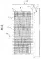
- Fig. 2 is a partially cutaway side view of the heat pipe type heat exchanger 11 of the present embodiment as shown in Fig. 1.
- the tank 2 of the heat pipe unit 10 is embedded in the base block 1 by one half of its height h, and the thin pipes 3 are upstanding in a row arrangement on top of the tank 2 at a predetermined spacing.
- a large number of thin fins 4 are provided so as to connect the thin pipes 3 to one another.
- the shape in cross section of the tank as mentioned above may be circular or square.
- a tank of circular cross section has a high strength and is easily available, and advantageously leads to cutting costs.
- a tank of square cross section, when embedded in the base block, may increase the contact area between the tank and the base block to realize an improved cooling efficiency.
- the tank and the base block are preferably joined together through soldering or the like. This is because a tight joint leads to better thermal conductivity and to an improved cooling efficiency.
- Fig. 3 is a view illustrating the direction of air blowing for the heat pipe type heat exchanger of the present embodiment as shown in Fig. 1.
- a fan may be used to send air from a lateral direction of the fins 4 to effect forced cooling which may further enhance the cooling efficiency.
- Fig. 4 is a partially cutaway side view of a heat pipe unit according to a second embodiment of the present invention.
- a heat pipe unit 12 of the second embodiment differs from the heat pipe unit 10 of the first embodiment as shown in Fig. 2 in that the tank 2, which has a large cross-sectional area, is comprised of a pipe of circular cross section, and the pipe is provided on its inner surface with grooves 8 so as to enlarge the area of heat-transfer surface and perform heat exchange with an improved efficiency.
- Shown in Fig. 5 is an enlarged view of the inner surface of the tank 2.
- the inner surface of the tank 2 is formed, with a thread chaser, with grooves 8 in a spiral fashion having a depth d, width w and pitch p.
- ⁇ indicates the inclination of the grooves 8 relative to the axis of the tank-constituting pipe.
- a pipe of circular cross section is employed as the pipe with a large cross-sectional area and has spiral grooves 8 formed on its inner surface
- a pipe having a cross section other than a circular cross section such as a square cross section or the like may also be used.
- the grooves are not limited to spiral ones and may be of any type such as straight grooves extending longitudinally along the pipe insofar as they are suited for the purpose of increasing the area of heat-transfer surface. From the viewpoint of the effect, however, spiral grooves are preferred.
- the grooves may be formed over all or part of the inner surface of the pipe with a large cross-sectional area.
- the inner surface of the tank 2 was formed with a thread chasing tap with spiral grooves 8 having depths d, widths w, and pitches p as shown in Table 1 under Experiments Nos. 1-8 and 11.
- the same pipe but with straight grooves extending along its longitudinal direction was also used in Experiment No. 9. Furthermore, for comparison, the same pipe but with no grooves formed was used in Experiment No. 10.
- the depth and width of a groove had less influence on the cooling capability.
- the depth and width of a groove are subject to limitations by the wall thickness of the pipe to be used.
- the cross section of the groove is not restricted to a triangular shape and may be of any shape such as trapezoidal, circular, polygonal, square or the like, but the groove of triangular cross section may be advantageously formed with a common thread chaser.
- a mesh of metal such as copper or the like may be inserted into the pipe to obtain the same effect or advantage.
- the thin pipes 3 may be internally provided with grooves and/or a mesh of metal as described above so as to enlarge the area of the heat-transfer surface.
- the heat pipe type heat exchanger will have many uses for cooling vehicle-mounted semiconductor control devices, it is preferable that the tank is secured to the base block with mounting hardware.
- the thin pipes are secured to the base block with mounting hardware.
- a vehicle-mounted heat pipe type heat exchanger will be provided which may withstand vigorous vibrations during running of the vehicle.
- Fig. 7 shows an example of a method of securing the tank 2 to the base block 1, the tank 2 being constituted by a pipe having a circular cross section.
- a U-shaped mounting part 14 and screws 16 are preferably used to screw the tank 2 to the base block 1, so as to increase the strength.
- a plate-like mounting part 15 and screws 16 may also be used to screw and, secure the tank 2 to the base block 1.
- Fig. 8 shows an example of a method of securing a tank to the base block, the tank being constituted by a pipe of square cross section. Where the pipe of square cross section is used to constitute the tank, the maximum contact area between the tank 2 and the base block 1 will be obtained if the tank 2 is embedded in the base block 1 up to the top of its sides as shown in Fig. 8.
- a plate-like mounting part 15 and screws 16 are preferably used to screw the tank 2 to the base block 1, so as to increase the strength.
- the tank may be formed from a pipe produced through extrusion or may be formed from plates welded together.
- the base block 1 and the tank 2 are preferably joined tightly together through welding at their joint from the viewpoint of thermal conductivity.
- each upstanding thin pipe is reinforced at an upper portion thereof with mounting hardware or the like.
- mounting hardware include a U-shaped mounting part 7 as shown in Fig. 9. As shown in Fig. 9, if the tank 2 and the thin pipes 3 are screwed to the base block 1 by using the mounting hardware 14 and 7, sufficient strength to enable withstanding vigorous vibrations will be obtained.
- a heat pipe type heat exchanger is comprised of a metal base block and a plurality of heat pipe units, with the tanks 2 of the latter embedded in a row in the base block.
- FIG. 10 An example of a heat pipe type heat exchanger is shown in Figs. 10 and 11, in which a plurality of heat pipe units 22 are embedded in a row in a metal base block 1.
- Fig. 10 is a side view
- Fig. 11 is a top view showing the layout.
- four heat pipe units 22 are arranged in a row to be embedded in the base block 1.
- Two sets of fins 4, longitudinally divided with a spacing therebetween, are fitted over the thin pipes 3 of two neighboring heat pipe units.
- the thin pipes 3, when seen in top view are arranged as a whole in a grid-like manner.
- the thus arranged heat pipe type heat exchanger is advantageously easier to produce than one in which the thin pipes are arranged in a staggered manner as will be described below.
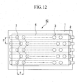
- a heat pipe type heat exchanger 42 according to the fourth embodiment of the present invention is shown in top view in Fig. 12.
- This is another example of a heat pipe type heat exchanger comprised of a plurality of heat pipe units.
- five heat pipe units are used, with their tanks 2 arranged in parallel and spaced uniformly.
- the thin pipes 3 upstanding on the tank 2 of each heat pipe unit at a predetermined spacing, when seen in top view, are arranged in a staggered manner. If the thin pipes 3 are arranged in a staggered manner in top view, an improved cooling efficiency may be realized owing to the effect of turbulent flow.
- the fins 4 are mounted on all the thin pipes 3 in this example as shown in Fig. 12, they may be divided into several blocks and mounted on the relevant pipes 3.
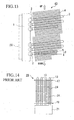
- a fifth embodiment of the present invention allows for a heat pipe type heat exchanger to be mounted vertically and is shown in Fig. 13.
- a heat pipe type heat exchanger With, for example, a vehicle-mounted semiconductor control device, there are cases where the mounting position of a heat pipe type heat exchanger is restricted and the heat exchanger must be installed vertically in a confined, vertically-extending space.
- the base block 1 with the semiconductor device 5 joined thereto is mounted substantially vertically as shown in Fig. 13, and a plurality of tanks 2 are embedded in the base block 1 to extend in a horizontal direction.
- Each thin pipe 3 is joined to the corresponding heat pipe unit at an angle of ⁇ ° relative to the horizontal plane.
- the thus constructed heat pipe type heat exchanger 43 may be installed vertically in a confined space.
- each thin pipe 3 is inclined by ⁇ ° relative to the horizontal plane is to make it easier for the condensed liquid working fluid inside each thin pipe 3 to return to the corresponding tank 2.
- the angle ⁇ is preferably in the range of 5 to 10°, and more preferably around 7°.
- the heat pipe type heat exchanger of the present invention has a structure in which part of the tank of the heat pipe unit is embedded in a base block of large thermal capacity such that the dissipation of heat will be further accelerated.
- the heat pipe unit and the heat pipe type heat exchanger of the present invention are simple in structure and easy to produce, and have a high thermal efficiency for their compact size.
- the heat pipe unit of the present invention is simple in structure and is easy to produce, and has a good thermal efficiency. Furthermore, by increasing the number of heat pipe units as required, a heat pipe type heat exchanger may be constructed that is suited for cooling a semiconductor device of large heating value.
Landscapes
- Engineering & Computer Science (AREA)
- Physics & Mathematics (AREA)
- Thermal Sciences (AREA)
- Mechanical Engineering (AREA)
- General Engineering & Computer Science (AREA)
- Life Sciences & Earth Sciences (AREA)
- Sustainable Development (AREA)
- Geometry (AREA)
- Cooling Or The Like Of Semiconductors Or Solid State Devices (AREA)
- Heat-Exchange Devices With Radiators And Conduit Assemblies (AREA)
Applications Claiming Priority (4)
| Application Number | Priority Date | Filing Date | Title |
|---|---|---|---|
| JP2002226634 | 2002-08-02 | ||
| JP2002226634 | 2002-08-02 | ||
| JP2003166557 | 2003-06-11 | ||
| JP2003166557A JP2004125381A (ja) | 2002-08-02 | 2003-06-11 | ヒートパイプユニット及びヒートパイプ冷却器 |
Publications (3)
| Publication Number | Publication Date |
|---|---|
| EP1387139A2 true EP1387139A2 (fr) | 2004-02-04 |
| EP1387139A3 EP1387139A3 (fr) | 2006-09-06 |
| EP1387139B1 EP1387139B1 (fr) | 2013-10-23 |
Family
ID=30117515
Family Applications (1)
| Application Number | Title | Priority Date | Filing Date |
|---|---|---|---|
| EP03016632.6A Expired - Lifetime EP1387139B1 (fr) | 2002-08-02 | 2003-07-30 | Échangeur de chaleur avec caloducs |
Country Status (5)
| Country | Link |
|---|---|
| US (1) | US6843307B2 (fr) |
| EP (1) | EP1387139B1 (fr) |
| JP (1) | JP2004125381A (fr) |
| KR (1) | KR100606283B1 (fr) |
| CN (1) | CN100347852C (fr) |
Cited By (8)
| Publication number | Priority date | Publication date | Assignee | Title |
|---|---|---|---|---|
| WO2006077360A1 (fr) * | 2005-01-20 | 2006-07-27 | Leo Lamb | Radiateur ameliore |
| WO2006094505A3 (fr) * | 2005-03-07 | 2007-03-01 | Asetek As | Systeme de refroidissement pour des appareils electroniques, en particulier des ordinateurs |
| EP2112689A3 (fr) * | 2008-04-24 | 2012-06-13 | ABB Research Ltd. | Dispositif d'échange de chaleur |
| FR2998359A1 (fr) * | 2012-11-19 | 2014-05-23 | Cockerill Maintenance & Ingenierie Sa | Dispositif de recuperation de chaleur et installation de stockage de produits chauds |
| EP3006881A1 (fr) * | 2014-10-08 | 2016-04-13 | Mersen Canada Toronto Inc. | Procédés de fabrication d'un caloduc complexe et plaque de transfert de chaleur comprenant une ouverture à cet effet |
| EP3006885A1 (fr) * | 2014-10-08 | 2016-04-13 | Mersen Canada Toronto Inc. | Ensemble de caloducs hybride avec des ailettes liées à la plaque de base |
| CN110230938A (zh) * | 2018-03-06 | 2019-09-13 | 山东豪迈化工技术有限公司 | 一种换热装置和微反应器 |
| CN113532170A (zh) * | 2020-04-15 | 2021-10-22 | 华为技术有限公司 | 一种两相相变散热器件及终端设备 |
Families Citing this family (46)
| Publication number | Priority date | Publication date | Assignee | Title |
|---|---|---|---|---|
| US7106589B2 (en) * | 2003-12-23 | 2006-09-12 | Aall Power Heatsinks, Inc. | Heat sink, assembly, and method of making |
| US6978828B1 (en) | 2004-06-18 | 2005-12-27 | Schlumberger Technology Corporation | Heat pipe cooling system |
| US7139172B2 (en) * | 2004-07-01 | 2006-11-21 | International Business Machines Corporation | Apparatus and methods for microchannel cooling of semiconductor integrated circuit packages |
| TWM261983U (en) * | 2004-08-23 | 2005-04-11 | Inventec Corp | Tubular radiator |
| CN100529637C (zh) * | 2004-09-01 | 2009-08-19 | 鸿富锦精密工业(深圳)有限公司 | 热管的制备方法 |
| TWI257992B (en) * | 2004-09-13 | 2006-07-11 | Neobulb Technologies Inc | Lighting device with highly efficient heat dissipation structure |
| TWI275770B (en) * | 2004-12-24 | 2007-03-11 | Foxconn Tech Co Ltd | Heat dissipation device with heat pipes |
| KR200387377Y1 (ko) * | 2005-03-18 | 2005-06-17 | 배민현 | 히트파이프 열교환기의 전열관 구조 |
| TW200706100A (en) * | 2005-07-29 | 2007-02-01 | Hon Hai Prec Ind Co Ltd | Heat sink |
| CN100480609C (zh) * | 2005-10-11 | 2009-04-22 | 富准精密工业(深圳)有限公司 | 热管制造方法 |
| US7545630B2 (en) * | 2005-11-01 | 2009-06-09 | Dell Products L.P. | Method and apparatus for thermal dissipation |
| US7422052B2 (en) * | 2006-04-20 | 2008-09-09 | Delphi Technologies, Inc. | Low profile thermosiphon |
| US7420810B2 (en) * | 2006-09-12 | 2008-09-02 | Graftech International Holdings, Inc. | Base heat spreader with fins |
| US20100132924A1 (en) * | 2007-04-27 | 2010-06-03 | National University Of Singapore | Cooling device for electronic components |
| TW200926945A (en) * | 2007-12-12 | 2009-06-16 | chong-xian Huang | Cylindrical heat dissipater equipped with cooling fins |
| KR200450584Y1 (ko) * | 2007-12-12 | 2010-10-13 | 충-시엔 후앙 | 히트 싱크 |
| JP2010060164A (ja) * | 2008-09-01 | 2010-03-18 | Sumitomo Light Metal Ind Ltd | ヒートパイプ式ヒートシンク |
| KR101621565B1 (ko) * | 2010-06-07 | 2016-05-16 | 한온시스템 주식회사 | 응축기 |
| CN102454442A (zh) * | 2010-10-28 | 2012-05-16 | 兰凯 | 一种火电厂循环水回用冷却系统 |
| US9170057B2 (en) * | 2011-02-16 | 2015-10-27 | Thermal Resource Technologies, Inc. | Evacuated tubes for solar thermal energy collection |
| KR101263898B1 (ko) | 2011-07-08 | 2013-05-13 | (주)에이치박엔지니어링 | 히트파이프 |
| KR101382454B1 (ko) * | 2011-08-17 | 2014-04-08 | 현대모비스 주식회사 | 헤드램프의 방열장치 |
| US20130180688A1 (en) * | 2012-01-16 | 2013-07-18 | Cooler Master Co., Ltd. | Heat-dissipating module and method for manufacturing the same |
| JP2014152983A (ja) * | 2013-02-07 | 2014-08-25 | Mitsubishi Alum Co Ltd | 冷却器 |
| US9863716B2 (en) | 2013-07-26 | 2018-01-09 | Hamilton Sundstrand Corporation | Heat exchanger with embedded heat pipes |
| KR20170097057A (ko) * | 2014-12-25 | 2017-08-25 | 미츠비시 알루미늄 컴파니 리미티드 | 냉각기 |
| WO2016104729A1 (fr) * | 2014-12-25 | 2016-06-30 | 三菱アルミニウム株式会社 | Refroidisseur |
| CN104654655B (zh) * | 2015-02-03 | 2016-11-23 | 青岛海尔股份有限公司 | 烧结热管及具有其的半导体制冷冰箱 |
| CN104729182B (zh) * | 2015-02-03 | 2016-11-23 | 青岛海尔股份有限公司 | 半导体制冷冰箱 |
| CN104654670B (zh) * | 2015-02-03 | 2016-11-02 | 青岛海尔股份有限公司 | 换热装置及具有其的半导体制冷冰箱 |
| US10119766B2 (en) * | 2015-12-01 | 2018-11-06 | Asia Vital Components Co., Ltd. | Heat dissipation device |
| US10663231B2 (en) * | 2016-06-08 | 2020-05-26 | Delta Electronics, Inc. | Manufacturing method of heat conducting device |
| JP6674335B2 (ja) * | 2016-06-24 | 2020-04-01 | 土山産業株式会社 | 地中熱利用ヒートパイプ式空調装置およびその構成用ユニットならびに空調方法 |
| CN106813095A (zh) * | 2017-03-27 | 2017-06-09 | 中国石油大学(华东) | 一种lng储罐翻滚抑制装置 |
| US10462932B2 (en) * | 2017-11-01 | 2019-10-29 | Hewlett Packard Enterprise Development Lp | Memory module cooler with vapor chamber device connected to heat pipes |
| CN107731765B (zh) * | 2017-11-16 | 2020-02-07 | 安徽祥博传热科技有限公司 | 一种一体化液冷散热器 |
| WO2019131834A1 (fr) | 2017-12-28 | 2019-07-04 | 古河電気工業株式会社 | Dispositif de refroidissement |
| CN212673920U (zh) * | 2017-12-28 | 2021-03-09 | 古河电气工业株式会社 | 散热器 |
| DE112018007666T5 (de) * | 2018-05-30 | 2021-02-25 | Mitsubishi Electric Corporation | Kühlvorrichtung |
| US20200068745A1 (en) * | 2018-08-22 | 2020-02-27 | Asia Vital Components Co., Ltd. | Heat dissipation structure of electronic device |
| JP6582114B1 (ja) | 2018-11-30 | 2019-09-25 | 古河電気工業株式会社 | ヒートシンク |
| JP6640401B1 (ja) * | 2019-04-18 | 2020-02-05 | 古河電気工業株式会社 | ヒートシンク |
| JP6697112B1 (ja) * | 2019-05-10 | 2020-05-20 | 古河電気工業株式会社 | ヒートシンク |
| US11035620B1 (en) * | 2020-11-19 | 2021-06-15 | Richard W. Trent | Loop heat pipe transfer system with manifold |
| KR102741373B1 (ko) | 2024-01-15 | 2024-12-11 | (주)대홍기업 | 열교환기 및 열교환기 제조방법 |
| WO2025171252A1 (fr) * | 2024-02-07 | 2025-08-14 | University Of Utah Research Foundation | Systèmes de collecte d'eau atmosphérique |
Citations (2)
| Publication number | Priority date | Publication date | Assignee | Title |
|---|---|---|---|---|
| JPH08210789A (ja) | 1995-02-02 | 1996-08-20 | Furukawa Electric Co Ltd:The | ヒートパイプ冷却器 |
| JP2002013467A (ja) | 2000-04-28 | 2002-01-18 | Mitsubishi Electric Corp | 風力発電装置 |
Family Cites Families (22)
| Publication number | Priority date | Publication date | Assignee | Title |
|---|---|---|---|---|
| US2024716A (en) * | 1934-09-29 | 1935-12-17 | Westinghouse Electric & Mfg Co | Transformer air-blast equipment |
| SE382282B (sv) * | 1971-02-13 | 1976-01-19 | Bbc Brown Boveri & Cie | For minst en halvledarskivcell avsett tryckfeste med kylanordning, innefattande vermeror med inre kapillerstruktur. |
| JPS5433710B2 (fr) * | 1973-02-12 | 1979-10-22 | ||
| GB1433542A (en) * | 1973-07-24 | 1976-04-28 | Q Dot Corp | Method of producing a wick in a thermal transfer tube |
| US4209487A (en) * | 1975-06-02 | 1980-06-24 | Monsanto Company | Method for corrosion inhibition |
| US4145708A (en) * | 1977-06-13 | 1979-03-20 | General Electric Company | Power module with isolated substrates cooled by integral heat-energy-removal means |
| JPS549048A (en) * | 1977-06-22 | 1979-01-23 | Toyota Motor Corp | Heat exchanger, thermosiphon, and production of thermosiphon |
| AT358081B (de) * | 1977-10-28 | 1980-08-25 | Kabel Metallwerke Ghh | Vorrichtung zum transport von waermeenergie |
| JPS5741591A (en) * | 1980-08-26 | 1982-03-08 | Furukawa Electric Co Ltd:The | Heat pipe |
| JPS5956090A (ja) * | 1982-09-22 | 1984-03-31 | Hitachi Ltd | 熱伝達装置用容器及びその加工工具 |
| US4982274A (en) * | 1988-12-14 | 1991-01-01 | The Furukawa Electric Co., Ltd. | Heat pipe type cooling apparatus for semiconductor |
| DE4121534C2 (de) * | 1990-06-30 | 1998-10-08 | Toshiba Kawasaki Kk | Kühlvorrichtung |
| US5216580A (en) * | 1992-01-14 | 1993-06-01 | Sun Microsystems, Inc. | Optimized integral heat pipe and electronic circuit module arrangement |
| US5253702A (en) * | 1992-01-14 | 1993-10-19 | Sun Microsystems, Inc. | Integral heat pipe, heat exchanger, and clamping plate |
| JPH05243441A (ja) * | 1992-03-03 | 1993-09-21 | Ito Gijutsu Kenkiyuushitsu:Kk | 放熱装置 |
| JP3020790B2 (ja) * | 1993-12-28 | 2000-03-15 | 株式会社日立製作所 | ヒートパイプ式冷却装置とこれを用いた車両制御装置 |
| JPH08264694A (ja) * | 1995-03-20 | 1996-10-11 | Calsonic Corp | 電子部品用冷却装置 |
| JPH09191440A (ja) * | 1996-01-10 | 1997-07-22 | Fujitsu General Ltd | Pdpの放熱構造 |
| FR2777986B1 (fr) * | 1998-04-23 | 2000-07-28 | Ferraz | Echangeur de chaleur, notamment pour le refroidissement d'un composant electronique de puissance, et son procede de fabrication |
| US6237223B1 (en) * | 1999-05-06 | 2001-05-29 | Chip Coolers, Inc. | Method of forming a phase change heat sink |
| US6490160B2 (en) * | 1999-07-15 | 2002-12-03 | Incep Technologies, Inc. | Vapor chamber with integrated pin array |
| US6257323B1 (en) * | 2000-06-12 | 2001-07-10 | Ching-Sung Kuo | Heat dissipating device |
-
2003
- 2003-06-11 JP JP2003166557A patent/JP2004125381A/ja active Pending
- 2003-07-29 US US10/628,360 patent/US6843307B2/en not_active Expired - Lifetime
- 2003-07-30 EP EP03016632.6A patent/EP1387139B1/fr not_active Expired - Lifetime
- 2003-08-01 CN CNB031580386A patent/CN100347852C/zh not_active Expired - Lifetime
- 2003-08-01 KR KR1020030053400A patent/KR100606283B1/ko not_active Expired - Lifetime
Patent Citations (2)
| Publication number | Priority date | Publication date | Assignee | Title |
|---|---|---|---|---|
| JPH08210789A (ja) | 1995-02-02 | 1996-08-20 | Furukawa Electric Co Ltd:The | ヒートパイプ冷却器 |
| JP2002013467A (ja) | 2000-04-28 | 2002-01-18 | Mitsubishi Electric Corp | 風力発電装置 |
Cited By (10)
| Publication number | Priority date | Publication date | Assignee | Title |
|---|---|---|---|---|
| WO2006077360A1 (fr) * | 2005-01-20 | 2006-07-27 | Leo Lamb | Radiateur ameliore |
| WO2006094505A3 (fr) * | 2005-03-07 | 2007-03-01 | Asetek As | Systeme de refroidissement pour des appareils electroniques, en particulier des ordinateurs |
| US7926553B2 (en) | 2005-03-07 | 2011-04-19 | Asetek A/S | Cooling system for electronic devices, in particular, computers |
| EP2112689A3 (fr) * | 2008-04-24 | 2012-06-13 | ABB Research Ltd. | Dispositif d'échange de chaleur |
| FR2998359A1 (fr) * | 2012-11-19 | 2014-05-23 | Cockerill Maintenance & Ingenierie Sa | Dispositif de recuperation de chaleur et installation de stockage de produits chauds |
| BE1021752B1 (fr) * | 2012-11-19 | 2016-01-15 | Cockerill Maintenance & Ingenierie S.A. | Dispositif de recuperation de chaleur et installation de stockage de produits chauds |
| EP3006881A1 (fr) * | 2014-10-08 | 2016-04-13 | Mersen Canada Toronto Inc. | Procédés de fabrication d'un caloduc complexe et plaque de transfert de chaleur comprenant une ouverture à cet effet |
| EP3006885A1 (fr) * | 2014-10-08 | 2016-04-13 | Mersen Canada Toronto Inc. | Ensemble de caloducs hybride avec des ailettes liées à la plaque de base |
| CN110230938A (zh) * | 2018-03-06 | 2019-09-13 | 山东豪迈化工技术有限公司 | 一种换热装置和微反应器 |
| CN113532170A (zh) * | 2020-04-15 | 2021-10-22 | 华为技术有限公司 | 一种两相相变散热器件及终端设备 |
Also Published As
| Publication number | Publication date |
|---|---|
| US6843307B2 (en) | 2005-01-18 |
| JP2004125381A (ja) | 2004-04-22 |
| US20040069461A1 (en) | 2004-04-15 |
| KR100606283B1 (ko) | 2006-07-28 |
| EP1387139B1 (fr) | 2013-10-23 |
| CN1489204A (zh) | 2004-04-14 |
| EP1387139A3 (fr) | 2006-09-06 |
| KR20040012593A (ko) | 2004-02-11 |
| CN100347852C (zh) | 2007-11-07 |
Similar Documents
| Publication | Publication Date | Title |
|---|---|---|
| US6843307B2 (en) | Heat pipe unit and heat pipe type heat exchanger | |
| US11725883B2 (en) | Heat sink | |
| CN1257548C (zh) | 蒸发和冷凝制冷剂的冷却装置 | |
| US6360814B1 (en) | Cooling device boiling and condensing refrigerant | |
| US7604040B2 (en) | Integrated liquid cooled heat sink for electronic components | |
| JP4391366B2 (ja) | ヒートパイプを備えたヒートシンクおよびその製造方法 | |
| CN101377392A (zh) | 热交换器 | |
| US6725908B2 (en) | Cooling apparatus boiling and condensing refrigerant with effective performance in a tilted position | |
| US7093647B2 (en) | Ebullition cooling device for heat generating component | |
| US20050274496A1 (en) | Boiling cooler | |
| CN113613468A (zh) | 钎焊冷媒散热器 | |
| CN106954366A (zh) | 用于电力电子构件的换热器 | |
| CN121241668A (zh) | 功率变换设备 | |
| JP2011142298A (ja) | 沸騰冷却装置 | |
| JP3924674B2 (ja) | 発熱素子用沸騰冷却器 | |
| JP6534686B2 (ja) | 冷却器 | |
| US7278467B2 (en) | Liquid-cooled heat radiator kit | |
| CN210835974U (zh) | 用于电控组件散热的换热系统和计算机主机 | |
| CN117121189A (zh) | 用于将热量从电子热源传递到散热片的散热器 | |
| JP4877069B2 (ja) | 沸騰冷却装置 | |
| JP3804185B2 (ja) | 沸騰冷却装置 | |
| JP3810119B2 (ja) | 沸騰冷却装置 | |
| CN222692170U (zh) | 一种散热器及车载终端 | |
| KR100584770B1 (ko) | 라디에이터와 응축기가 일체로 구성된 일체형 열교환기 | |
| CN118274645A (zh) | 一种热管换热装置 |
Legal Events
| Date | Code | Title | Description |
|---|---|---|---|
| PUAI | Public reference made under article 153(3) epc to a published international application that has entered the european phase |
Free format text: ORIGINAL CODE: 0009012 |
|
| AK | Designated contracting states |
Kind code of ref document: A2 Designated state(s): AT BE BG CH CY CZ DE DK EE ES FI FR GB GR HU IE IT LI LU MC NL PT RO SE SI SK TR |
|
| AX | Request for extension of the european patent |
Extension state: AL LT LV MK |
|
| PUAL | Search report despatched |
Free format text: ORIGINAL CODE: 0009013 |
|
| AK | Designated contracting states |
Kind code of ref document: A3 Designated state(s): AT BE BG CH CY CZ DE DK EE ES FI FR GB GR HU IE IT LI LU MC NL PT RO SE SI SK TR |
|
| AX | Request for extension of the european patent |
Extension state: AL LT LV MK |
|
| 17P | Request for examination filed |
Effective date: 20061124 |
|
| AKX | Designation fees paid |
Designated state(s): DE FR |
|
| 17Q | First examination report despatched |
Effective date: 20090824 |
|
| RAP1 | Party data changed (applicant data changed or rights of an application transferred) |
Owner name: MITSUBISHI ALUMINUM CO.,LTD. |
|
| GRAP | Despatch of communication of intention to grant a patent |
Free format text: ORIGINAL CODE: EPIDOSNIGR1 |
|
| INTG | Intention to grant announced |
Effective date: 20130531 |
|
| GRAS | Grant fee paid |
Free format text: ORIGINAL CODE: EPIDOSNIGR3 |
|
| GRAA | (expected) grant |
Free format text: ORIGINAL CODE: 0009210 |
|
| AK | Designated contracting states |
Kind code of ref document: B1 Designated state(s): DE FR |
|
| REG | Reference to a national code |
Ref country code: DE Ref legal event code: R096 Ref document number: 60345122 Country of ref document: DE Effective date: 20131219 |
|
| REG | Reference to a national code |
Ref country code: DE Ref legal event code: R097 Ref document number: 60345122 Country of ref document: DE |
|
| PLBE | No opposition filed within time limit |
Free format text: ORIGINAL CODE: 0009261 |
|
| STAA | Information on the status of an ep patent application or granted ep patent |
Free format text: STATUS: NO OPPOSITION FILED WITHIN TIME LIMIT |
|
| 26N | No opposition filed |
Effective date: 20140724 |
|
| REG | Reference to a national code |
Ref country code: DE Ref legal event code: R097 Ref document number: 60345122 Country of ref document: DE Effective date: 20140724 |
|
| REG | Reference to a national code |
Ref country code: FR Ref legal event code: PLFP Year of fee payment: 14 |
|
| REG | Reference to a national code |
Ref country code: FR Ref legal event code: PLFP Year of fee payment: 15 |
|
| REG | Reference to a national code |
Ref country code: FR Ref legal event code: PLFP Year of fee payment: 16 |
|
| REG | Reference to a national code |
Ref country code: DE Ref legal event code: R082 Ref document number: 60345122 Country of ref document: DE Representative=s name: DENNEMEYER & ASSOCIATES S.A., DE Ref country code: DE Ref legal event code: R081 Ref document number: 60345122 Country of ref document: DE Owner name: ATAGO MFG CO., LTD., MIDORI-SHI, JP Free format text: FORMER OWNER: MITSUBISHI ALUMINUM CO., LTD., TOKIO/TOKYO, JP |
|
| PGFP | Annual fee paid to national office [announced via postgrant information from national office to epo] |
Ref country code: DE Payment date: 20220620 Year of fee payment: 20 |
|
| PGFP | Annual fee paid to national office [announced via postgrant information from national office to epo] |
Ref country code: FR Payment date: 20220720 Year of fee payment: 20 |
|
| REG | Reference to a national code |
Ref country code: DE Ref legal event code: R071 Ref document number: 60345122 Country of ref document: DE |