EP1277510A2 - Dialyseur - Google Patents
Dialyseur Download PDFInfo
- Publication number
- EP1277510A2 EP1277510A2 EP02015454A EP02015454A EP1277510A2 EP 1277510 A2 EP1277510 A2 EP 1277510A2 EP 02015454 A EP02015454 A EP 02015454A EP 02015454 A EP02015454 A EP 02015454A EP 1277510 A2 EP1277510 A2 EP 1277510A2
- Authority
- EP
- European Patent Office
- Prior art keywords
- dialyzer
- dialysate
- potting material
- fluid distribution
- dialysate fluid
- Prior art date
- Legal status (The legal status is an assumption and is not a legal conclusion. Google has not performed a legal analysis and makes no representation as to the accuracy of the status listed.)
- Granted
Links
Images

Classifications
-
- B—PERFORMING OPERATIONS; TRANSPORTING
- B01—PHYSICAL OR CHEMICAL PROCESSES OR APPARATUS IN GENERAL
- B01D—SEPARATION
- B01D61/00—Processes of separation using semi-permeable membranes, e.g. dialysis, osmosis or ultrafiltration; Apparatus, accessories or auxiliary operations specially adapted therefor
- B01D61/24—Dialysis ; Membrane extraction
- B01D61/30—Accessories; Auxiliary operation
-
- B—PERFORMING OPERATIONS; TRANSPORTING
- B01—PHYSICAL OR CHEMICAL PROCESSES OR APPARATUS IN GENERAL
- B01D—SEPARATION
- B01D61/00—Processes of separation using semi-permeable membranes, e.g. dialysis, osmosis or ultrafiltration; Apparatus, accessories or auxiliary operations specially adapted therefor
- B01D61/24—Dialysis ; Membrane extraction
- B01D61/28—Apparatus therefor
-
- A—HUMAN NECESSITIES
- A61—MEDICAL OR VETERINARY SCIENCE; HYGIENE
- A61M—DEVICES FOR INTRODUCING MEDIA INTO, OR ONTO, THE BODY; DEVICES FOR TRANSDUCING BODY MEDIA OR FOR TAKING MEDIA FROM THE BODY; DEVICES FOR PRODUCING OR ENDING SLEEP OR STUPOR
- A61M1/00—Suction or pumping devices for medical purposes; Devices for carrying-off, for treatment of, or for carrying-over, body-liquids; Drainage systems
- A61M1/14—Dialysis systems; Artificial kidneys; Blood oxygenators ; Reciprocating systems for treatment of body fluids, e.g. single needle systems for hemofiltration or pheresis
- A61M1/16—Dialysis systems; Artificial kidneys; Blood oxygenators ; Reciprocating systems for treatment of body fluids, e.g. single needle systems for hemofiltration or pheresis with membranes
-
- B—PERFORMING OPERATIONS; TRANSPORTING
- B01—PHYSICAL OR CHEMICAL PROCESSES OR APPARATUS IN GENERAL
- B01D—SEPARATION
- B01D2313/00—Details relating to membrane modules or apparatus
- B01D2313/10—Specific supply elements
Definitions
- This invention relates to the field of dialyzers typically used in hemodialysis and related medical procedures, and in particular to a design having a lengthened useful life, together with a method for manufacturing the same.
- Dialysis is a process which employs an artificial kidney to remove those toxins.
- a dialyzer which contains a semi-permeable membrane dividing the dialyzer into two chambers. Blood is pumped through one chamber and a dialysis solution through the second. As the blood flows by the dialysis fluid, separated by the semipermeable membrane, blood impurities such as urea and creatinine diffuse through the semi-permeable membrane into the dialysis solution by the diffusion, convection and absorption.
- the electrolyte concentration of the dialysis fluid is set so as to maintain electrolytic balance within the patient.
- Dialyzers often use a large number of microfibers encased in a chamber.
- the chamber is often a hollow cylinder open at both ends.
- Thousands of hollow semipermeable microfibers carry blood from one end to the opposite end so that blood flows through the microfibers in a first direction.
- Dialysate ports are also present on opposite ends of the chamber.
- One port carries dialysate into the chamber, the dialysate flows through the chamber in a countercurrent direction to the blood flow, and the other port carries the dialysate out of the chamber.
- the solute removal thus takes place across the semipermeable membrane that is the microfiber wall.
- This design produces a high surface area for solute removal in a relatively low volume device.
- microfiber interior channels to the blood lines, so that blood flows smoothly from the arterial blood line, into the microfiber interior channels where it can pass into and through the dialyzer chamber, and out the other end of the microfiber interior channels to the venous blood line.
- the dialysate ports in the cylinder wall near each end of the dialyzer present special challenges. It is desirable for the microfibers to be supported by the cylinder wall throughout their length, or as much of their length as possible, so that the dialysate fluid flow pressure on the microfibers does not distort them. Such distortion can result in their breaking, which allows mingling of blood and dialysate, or can obstruct the flow of blood through the microfiber interior channels.
- the dialysate fluid distribution ring is effectively an extension of the dialyzer cylinder wall.
- the dialysate port accesses the dialyzer chamber by means of an intermediate space defined at the radial inner side by the dialysate fluid distribution ring and at the radially outer side by an outer wall.
- the dialysate fluid distribution ring thus extends lateral support to the microfibers around the circumference of the microfiber bundle while still enhancing dialysate fluid distribution between the dialysate ports and the chamber.
- the dialysate fluid distribution ring edge has in the past been planar. Because the dialysate fluid distribution ring edge has been planar while the potting material surface has been curved, the width of the gap between the dialysate fluid distribution ring edge and the potting material has varied. This gap represents the space in which the microfiber bundle is unsupported by the dialyzer cylinder wall or by the dialysate fluid distribution ring. The dialysate fluid flow pressure between the microfiber interior channel and the dialyzer chamber interior tends to flex or distort the microfibers.
- dialyzers it is desirable for dialyzers to be filled with microfibers in a manner that supports the dialysate fluid flow pressure on the microfiber bundle in a uniform way to avoid differential forces on the microfibers which distorts, ruptures or obstructs them.
- the present invention overcomes the deficiencies of existing systems by use of a novel design for the dialyzer dialysate fluid distribution ring.
- This dialysate fluid distribution ring separates the dialyzer interior chamber from the dialysate ports.
- the dialysate fluid distribution ring edge distal from the centrifuge axis of rotation assumes a shape defined as an annulus cut by a cylinder perpendicular to be axis of the annulus.
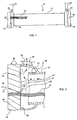
- a dialyzer 10 in accordance with a preferred embodiment of the invention is shown in Fig. 1.
- the overall shape of the dialyzer 10 is cylindrical, comprising a cylindrical body 12, a blood line inlet end 14 and a blood line outlet end 16.
- the ends 14 and 16 are preferably enlarged compared to the chamber body to accommodate a distribution ring described below.
- Proximate to the blood inlet end 14 is a dialysate outlet port 22, and proximate to the blood outlet end 16 is a dialysate inlet port 24.
- the cylindrical body 12 is filled with a microfiber bundle 18, only a fragment of which is shown in Fig. 1 for purposes of clarity.
- the microfibers 18 are potted in a polyurethane potting material 26 and 28 at each end 14 and 16.
- the dialysate inlet port 24 connects to a dialysate inlet line 25, and the dialysate outlet port 22 connects to a dialysate outlet line 23.
- FIG. 2 An enlarged sectional view of one end 14 of the dialyzer 10 is shown in Fig. 2 and Fig. 3.
- Fig. 3 omits all but the potting material for clarity.
- a portion of the microfiber bundle 18 is shown in Fig. 2, embedded in the potting material 26, while the rest of the microfiber bundle 18 is omitted for clarity.
- the interior surface 32 of the potting material 26 is not planar. Rather, geometrically speaking, it is the surface defined by the intersection of a cylinder with another cylinder. In this case, the first cylinder is the potting material 26.
- the intersecting, or cutting, cylinder which defines the potting material surface is an imaginary cylinder with a longitudinal axis extending up and down and intersecting with the longitudinal coaxial axes of the potting material 26 cylinder and the dialyzer cylindrical body 12.
- the resultant interior surface 32 of the potting material 26 has a circumferential edge that undulates.
- the overall thickness of the potting material 26 thus varies from relatively thick at two opposite points 36 and a point 37 opposite 36, to relatively thin at two opposite points that are offset 90° from point 36, at points 38 and 40.
- the potting material 26 ensures that the blood is confined to the interior channels of the microfiber bundle, and is unable to leak into the dialyzer chamber.
- a fitting (not shown) threaded onto the threads 48 of the dialyzer ends 14 and 16 serve to connect the blood lines to the dialyzer ends 14 and 16. Blood thereby flows from the arterial blood line into the interior bundle of the microfibers of the microfiber bundle 18, through the microfiber interior channels from one end 14 to the other end 16 of the dialyzer, and into the venous blood line (not shown) via another fitting (not shown) connecting that end 16 foot he venous blood line.
- a set of threads 48 is molded into the dialyzer 10 ends 14 and 16 to allow the ends to be capped during the step of centrifuging the potting material into the dialyzer chamber, and also to allow attachment to a fitting for connection to the blood lines. This portion of the manufacturing process is known in the art, and is not further described here.
- the design and configuration of the dialysate fluid distribution ring 51 is evident from Fig. 2.
- the dialysate fluid distribution ring 51 is an annular extension of the cylindrical dialyzer body 12.
- the dialyzer end 14 is radially spaced away from the dialysate fluid distribution ring 51 to define an annular space 56 between the end housing 58 and the dialysate fluid distribution ring 51.
- dialysate flows in the countercurrent direction to the blood flow.
- Dialysate flows from the inlet dialysate line 24 and through the inlet port 24 to enter the interior chamber of the dialyzer 10.
- the dialysate flows through the dialyzer interior chamber on the outside of the microfibers.
- the blood is thus separated from the dialysate by the semi-permeable membranes of the microfiber walls, which allow the transfer of liquids, toxins and nutrients by the diffusion, convection, & absorption.
- the dialysate then exits the dialyzer 10 through the dialysate outlet port 22 and into the dialysate outlet line 23.
- the dialysate fluid distribution ring circumferential edge 50 in past designs has been planar. Because the potting material 26 surface is not planar, due to the effect of the centrifugal molding process, the result in past designs has been a varying gap between the potting material surface and the distribution ring circumferential edge. Because the dialysate fluid distribution ring 51 provides support to the microfiber bundle 18 against the dialysate fluid flow pressure exerted during dialysis procedures, this support varies along the circumference of the dialysate fluid distribution ring 51 edge in past designs. This varying support tends to distort, rupture or obstruct the microfibers.
- the design of the dialysate fluid distribution ring 51 circumferential edge in the present invention is not planar. It instead is of an undulating shape that conforms to the undulating shape of the potting material 26 surface. This results in a gap between the potting material 26 surface and the dialysate fluid distribution ring 51 circumferential edge that does not vary but is instead substantially constant.
- substantially constant gap allows for substantially constant support of the microfiber bundle 18.
- substantially constant gap means for purposes of the claims below a gap which may be, but is not necessarily, exactly uniform, but which varies by an amount that lessens the distortion, rupturing or obstruction of the microfibers in comparison to the prior art planar circumferential edge of the dialysate fluid distribution ring.
- phase 1 included 3 seconds of flow through the dialysate port only; phase 2 included 3 seconds of flow through the blood port only, phase 3 included 3 seconds of flow through the dialysate and blood ports, and phase 4 was 3 seconds with no flow.
- phase 4 was 3 seconds with no flow.
- Each "cycle was defined as 11 minutes of sequential and repetitious 4-phase testing.
- Sample Type F80A Failed Cycle Sample Type: Prototype Failed Cycle Sample Type: Baxter CA 210 Failed Cycle Sample 1 1 Sample 1 26 Sample 1 1 Sample 2 4 Sample 2 14 Sample 2 1 Sample 3 1 Sample 3 14 Sample 3 1 Sample 4 1 Sample 4 12 Sample 4 1 Sample 5 1 Sample 5 7 Sample 5 1 Sample 6 1 Sample 6 25 Sample 6 1 Sample 7 1 Sample 7 1 Sample 8 1 Sample 8 26 Sample 8 1 Sample 9 6 Sample 9 12 Sample 9 1 Sample 10 1 Sample 10 8 Sample 10 1 Average 1.8 cycles Average 15.1 cycles Average 1 cycle S.D. 1.75 S.D. 7.74 S.D. 0
Landscapes
- Health & Medical Sciences (AREA)
- Urology & Nephrology (AREA)
- Engineering & Computer Science (AREA)
- Water Supply & Treatment (AREA)
- Chemical & Material Sciences (AREA)
- Chemical Kinetics & Catalysis (AREA)
- External Artificial Organs (AREA)
- Separation Using Semi-Permeable Membranes (AREA)
Applications Claiming Priority (4)
| Application Number | Priority Date | Filing Date | Title |
|---|---|---|---|
| US90707301A | 2001-07-17 | 2001-07-17 | |
| US907073 | 2001-07-17 | ||
| US969123 | 2001-10-01 | ||
| US09/969,123 US6802821B2 (en) | 2001-10-01 | 2001-10-01 | Dialyzer |
Publications (3)
| Publication Number | Publication Date |
|---|---|
| EP1277510A2 true EP1277510A2 (fr) | 2003-01-22 |
| EP1277510A3 EP1277510A3 (fr) | 2003-12-17 |
| EP1277510B1 EP1277510B1 (fr) | 2005-09-21 |
Family
ID=27129482
Family Applications (1)
| Application Number | Title | Priority Date | Filing Date |
|---|---|---|---|
| EP02015454A Expired - Lifetime EP1277510B1 (fr) | 2001-07-17 | 2002-07-11 | Dialyseur |
Country Status (6)
| Country | Link |
|---|---|
| EP (1) | EP1277510B1 (fr) |
| JP (1) | JP4150542B2 (fr) |
| AT (1) | ATE304894T1 (fr) |
| CA (1) | CA2390214C (fr) |
| DE (1) | DE60206222T2 (fr) |
| ES (1) | ES2248456T3 (fr) |
Families Citing this family (1)
| Publication number | Priority date | Publication date | Assignee | Title |
|---|---|---|---|---|
| CN100421771C (zh) | 2003-04-23 | 2008-10-01 | 旭化成可乐丽医疗株式会社 | 空心纤维膜型流体处理装置 |
Family Cites Families (5)
| Publication number | Priority date | Publication date | Assignee | Title |
|---|---|---|---|---|
| US4219426A (en) * | 1976-03-19 | 1980-08-26 | Organon Teknika B.V. | Dialysis device |
| US4201673A (en) * | 1977-07-04 | 1980-05-06 | Terumo Corporation | Apparatus for dialysis of solution |
| IT8353037U1 (it) * | 1983-03-10 | 1984-09-10 | Sorin Biomedica Spa | Apparecchio dializzatore a fibre cave |
| JPH08280796A (ja) * | 1995-04-19 | 1996-10-29 | Cytec Kk | 血液透析器 |
| ES2208806T3 (es) * | 1996-11-21 | 2004-06-16 | Fresenius Medical Care Deutschland Gmbh | Dispositivo separador de membranas de fibras huecas. |
-
2002
- 2002-07-02 CA CA002390214A patent/CA2390214C/fr not_active Expired - Lifetime
- 2002-07-11 DE DE60206222T patent/DE60206222T2/de not_active Expired - Lifetime
- 2002-07-11 ES ES02015454T patent/ES2248456T3/es not_active Expired - Lifetime
- 2002-07-11 EP EP02015454A patent/EP1277510B1/fr not_active Expired - Lifetime
- 2002-07-11 AT AT02015454T patent/ATE304894T1/de not_active IP Right Cessation
- 2002-07-17 JP JP2002208190A patent/JP4150542B2/ja not_active Expired - Lifetime
Also Published As
| Publication number | Publication date |
|---|---|
| EP1277510B1 (fr) | 2005-09-21 |
| ES2248456T3 (es) | 2006-03-16 |
| ATE304894T1 (de) | 2005-10-15 |
| DE60206222T2 (de) | 2006-07-13 |
| JP2003102833A (ja) | 2003-04-08 |
| CA2390214A1 (fr) | 2003-01-17 |
| JP4150542B2 (ja) | 2008-09-17 |
| DE60206222D1 (de) | 2006-02-02 |
| CA2390214C (fr) | 2009-09-08 |
| EP1277510A3 (fr) | 2003-12-17 |
Similar Documents
| Publication | Publication Date | Title |
|---|---|---|
| KR100649260B1 (ko) | 이중-스테이지 여과 카트리지 | |
| US7524417B2 (en) | Dialyzer and method for manufacturing the same | |
| US8142383B2 (en) | Fluid distribution module and extracorporeal blood circuit including such a module | |
| US8048209B2 (en) | Degassing device and end-cap assembly for a filter including such a degassing device | |
| EP2313125B1 (fr) | Dialyseur à double faisceau de fibres | |
| US3882024A (en) | Header for stagnation-sensitive liquids | |
| US6802821B2 (en) | Dialyzer | |
| JP6908394B2 (ja) | 中空糸膜モジュール及びその製造方法 | |
| EP1277510B1 (fr) | Dialyseur | |
| WO2016130128A1 (fr) | Dialyseur à double faisceau de fibres amélioré | |
| JP2000042100A (ja) | 中空糸膜型流体処理装置 | |
| JPH04305229A (ja) | 中空糸型物質移動装置 | |
| US20240293782A1 (en) | Hollow-fibre membrane filter having improved separation properties | |
| US20070102340A1 (en) | Blood treatment filter and method of manufacturing | |
| Salyer et al. | The monsanto polyacrylonitrile hollow‐fiber artificial kidney | |
| Wiese | 3.1 Introduction The use of membranes in extracorporeal systems connected to the human body started in the 1940s with Kolff’s first use of an artificial kidney. Since that time, the | |
| HK1058162B (en) | Dual-stage filtration cartridge |
Legal Events
| Date | Code | Title | Description |
|---|---|---|---|
| PUAI | Public reference made under article 153(3) epc to a published international application that has entered the european phase |
Free format text: ORIGINAL CODE: 0009012 |
|
| AK | Designated contracting states |
Kind code of ref document: A2 Designated state(s): AT BE BG CH CY CZ DE DK EE ES FI FR GB GR IE IT LI LU MC NL PT SE SK TR |
|
| AX | Request for extension of the european patent |
Free format text: AL;LT;LV;MK;RO;SI |
|
| PUAL | Search report despatched |
Free format text: ORIGINAL CODE: 0009013 |
|
| AK | Designated contracting states |
Kind code of ref document: A3 Designated state(s): AT BE BG CH CY CZ DE DK EE ES FI FR GB GR IE IT LI LU MC NL PT SE SK TR |
|
| AX | Request for extension of the european patent |
Extension state: AL LT LV MK RO SI |
|
| 17P | Request for examination filed |
Effective date: 20040227 |
|
| AKX | Designation fees paid |
Designated state(s): AT BE BG CH CY CZ DE DK EE ES FI FR GB GR IE IT LI LU MC NL PT SE SK TR |
|
| GRAP | Despatch of communication of intention to grant a patent |
Free format text: ORIGINAL CODE: EPIDOSNIGR1 |
|
| GRAS | Grant fee paid |
Free format text: ORIGINAL CODE: EPIDOSNIGR3 |
|
| GRAA | (expected) grant |
Free format text: ORIGINAL CODE: 0009210 |
|
| AK | Designated contracting states |
Kind code of ref document: B1 Designated state(s): AT BE BG CH CY CZ DE DK EE ES FI FR GB GR IE IT LI LU MC NL PT SE SK TR |
|
| PG25 | Lapsed in a contracting state [announced via postgrant information from national office to epo] |
Ref country code: NL Free format text: LAPSE BECAUSE OF FAILURE TO SUBMIT A TRANSLATION OF THE DESCRIPTION OR TO PAY THE FEE WITHIN THE PRESCRIBED TIME-LIMIT Effective date: 20050921 Ref country code: LI Free format text: LAPSE BECAUSE OF FAILURE TO SUBMIT A TRANSLATION OF THE DESCRIPTION OR TO PAY THE FEE WITHIN THE PRESCRIBED TIME-LIMIT Effective date: 20050921 Ref country code: FI Free format text: LAPSE BECAUSE OF FAILURE TO SUBMIT A TRANSLATION OF THE DESCRIPTION OR TO PAY THE FEE WITHIN THE PRESCRIBED TIME-LIMIT Effective date: 20050921 Ref country code: CH Free format text: LAPSE BECAUSE OF FAILURE TO SUBMIT A TRANSLATION OF THE DESCRIPTION OR TO PAY THE FEE WITHIN THE PRESCRIBED TIME-LIMIT Effective date: 20050921 Ref country code: SK Free format text: LAPSE BECAUSE OF FAILURE TO SUBMIT A TRANSLATION OF THE DESCRIPTION OR TO PAY THE FEE WITHIN THE PRESCRIBED TIME-LIMIT Effective date: 20050921 Ref country code: CZ Free format text: LAPSE BECAUSE OF FAILURE TO SUBMIT A TRANSLATION OF THE DESCRIPTION OR TO PAY THE FEE WITHIN THE PRESCRIBED TIME-LIMIT Effective date: 20050921 Ref country code: AT Free format text: LAPSE BECAUSE OF FAILURE TO SUBMIT A TRANSLATION OF THE DESCRIPTION OR TO PAY THE FEE WITHIN THE PRESCRIBED TIME-LIMIT Effective date: 20050921 Ref country code: BE Free format text: LAPSE BECAUSE OF FAILURE TO SUBMIT A TRANSLATION OF THE DESCRIPTION OR TO PAY THE FEE WITHIN THE PRESCRIBED TIME-LIMIT Effective date: 20050921 |
|
| REG | Reference to a national code |
Ref country code: GB Ref legal event code: FG4D |
|
| REG | Reference to a national code |
Ref country code: CH Ref legal event code: EP |
|
| REG | Reference to a national code |
Ref country code: IE Ref legal event code: FG4D |
|
| REF | Corresponds to: |
Ref document number: 60206222 Country of ref document: DE Date of ref document: 20051027 Kind code of ref document: P |
|
| PG25 | Lapsed in a contracting state [announced via postgrant information from national office to epo] |
Ref country code: GR Free format text: LAPSE BECAUSE OF FAILURE TO SUBMIT A TRANSLATION OF THE DESCRIPTION OR TO PAY THE FEE WITHIN THE PRESCRIBED TIME-LIMIT Effective date: 20051221 Ref country code: DK Free format text: LAPSE BECAUSE OF FAILURE TO SUBMIT A TRANSLATION OF THE DESCRIPTION OR TO PAY THE FEE WITHIN THE PRESCRIBED TIME-LIMIT Effective date: 20051221 Ref country code: BG Free format text: LAPSE BECAUSE OF FAILURE TO SUBMIT A TRANSLATION OF THE DESCRIPTION OR TO PAY THE FEE WITHIN THE PRESCRIBED TIME-LIMIT Effective date: 20051221 Ref country code: SE Free format text: LAPSE BECAUSE OF FAILURE TO SUBMIT A TRANSLATION OF THE DESCRIPTION OR TO PAY THE FEE WITHIN THE PRESCRIBED TIME-LIMIT Effective date: 20051221 |
|
| REF | Corresponds to: |
Ref document number: 60206222 Country of ref document: DE Date of ref document: 20060202 Kind code of ref document: P |
|
| PG25 | Lapsed in a contracting state [announced via postgrant information from national office to epo] |
Ref country code: PT Free format text: LAPSE BECAUSE OF FAILURE TO SUBMIT A TRANSLATION OF THE DESCRIPTION OR TO PAY THE FEE WITHIN THE PRESCRIBED TIME-LIMIT Effective date: 20060221 |
|
| NLV1 | Nl: lapsed or annulled due to failure to fulfill the requirements of art. 29p and 29m of the patents act | ||
| REG | Reference to a national code |
Ref country code: ES Ref legal event code: FG2A Ref document number: 2248456 Country of ref document: ES Kind code of ref document: T3 |
|
| REG | Reference to a national code |
Ref country code: CH Ref legal event code: PL |
|
| ET | Fr: translation filed | ||
| PG25 | Lapsed in a contracting state [announced via postgrant information from national office to epo] |
Ref country code: IE Free format text: LAPSE BECAUSE OF NON-PAYMENT OF DUE FEES Effective date: 20060711 |
|
| PLBE | No opposition filed within time limit |
Free format text: ORIGINAL CODE: 0009261 |
|
| STAA | Information on the status of an ep patent application or granted ep patent |
Free format text: STATUS: NO OPPOSITION FILED WITHIN TIME LIMIT |
|
| PG25 | Lapsed in a contracting state [announced via postgrant information from national office to epo] |
Ref country code: MC Free format text: LAPSE BECAUSE OF NON-PAYMENT OF DUE FEES Effective date: 20060731 |
|
| 26N | No opposition filed |
Effective date: 20060622 |
|
| REG | Reference to a national code |
Ref country code: IE Ref legal event code: MM4A |
|
| PG25 | Lapsed in a contracting state [announced via postgrant information from national office to epo] |
Ref country code: EE Free format text: LAPSE BECAUSE OF FAILURE TO SUBMIT A TRANSLATION OF THE DESCRIPTION OR TO PAY THE FEE WITHIN THE PRESCRIBED TIME-LIMIT Effective date: 20050921 |
|
| PG25 | Lapsed in a contracting state [announced via postgrant information from national office to epo] |
Ref country code: TR Free format text: LAPSE BECAUSE OF FAILURE TO SUBMIT A TRANSLATION OF THE DESCRIPTION OR TO PAY THE FEE WITHIN THE PRESCRIBED TIME-LIMIT Effective date: 20050921 Ref country code: LU Free format text: LAPSE BECAUSE OF NON-PAYMENT OF DUE FEES Effective date: 20060711 |
|
| PG25 | Lapsed in a contracting state [announced via postgrant information from national office to epo] |
Ref country code: CY Free format text: LAPSE BECAUSE OF FAILURE TO SUBMIT A TRANSLATION OF THE DESCRIPTION OR TO PAY THE FEE WITHIN THE PRESCRIBED TIME-LIMIT Effective date: 20050921 |
|
| REG | Reference to a national code |
Ref country code: FR Ref legal event code: PLFP Year of fee payment: 15 |
|
| REG | Reference to a national code |
Ref country code: FR Ref legal event code: PLFP Year of fee payment: 16 |
|
| REG | Reference to a national code |
Ref country code: FR Ref legal event code: PLFP Year of fee payment: 17 |
|
| PGFP | Annual fee paid to national office [announced via postgrant information from national office to epo] |
Ref country code: FR Payment date: 20210623 Year of fee payment: 20 Ref country code: IT Payment date: 20210622 Year of fee payment: 20 |
|
| PGFP | Annual fee paid to national office [announced via postgrant information from national office to epo] |
Ref country code: GB Payment date: 20210623 Year of fee payment: 20 |
|
| PGFP | Annual fee paid to national office [announced via postgrant information from national office to epo] |
Ref country code: ES Payment date: 20210802 Year of fee payment: 20 Ref country code: DE Payment date: 20210622 Year of fee payment: 20 |
|
| REG | Reference to a national code |
Ref country code: DE Ref legal event code: R071 Ref document number: 60206222 Country of ref document: DE |
|
| REG | Reference to a national code |
Ref country code: ES Ref legal event code: FD2A Effective date: 20220801 |
|
| REG | Reference to a national code |
Ref country code: GB Ref legal event code: PE20 Expiry date: 20220710 |
|
| PG25 | Lapsed in a contracting state [announced via postgrant information from national office to epo] |
Ref country code: GB Free format text: LAPSE BECAUSE OF EXPIRATION OF PROTECTION Effective date: 20220710 Ref country code: ES Free format text: LAPSE BECAUSE OF EXPIRATION OF PROTECTION Effective date: 20220712 |