EP1279421A1 - Bindungsplatte und Gleitbrett mit einer solchen Einrichtung - Google Patents
Bindungsplatte und Gleitbrett mit einer solchen Einrichtung Download PDFInfo
- Publication number
- EP1279421A1 EP1279421A1 EP02356133A EP02356133A EP1279421A1 EP 1279421 A1 EP1279421 A1 EP 1279421A1 EP 02356133 A EP02356133 A EP 02356133A EP 02356133 A EP02356133 A EP 02356133A EP 1279421 A1 EP1279421 A1 EP 1279421A1
- Authority
- EP
- European Patent Office
- Prior art keywords
- support device
- lateral
- longitudinal parts
- gliding board
- parts
- Prior art date
- Legal status (The legal status is an assumption and is not a legal conclusion. Google has not performed a legal analysis and makes no representation as to the accuracy of the status listed.)
- Granted
Links
- 230000027455 binding Effects 0.000 claims abstract description 30
- 238000009739 binding Methods 0.000 claims abstract description 30
- 230000000295 complement effect Effects 0.000 claims abstract description 10
- 230000001681 protective effect Effects 0.000 claims description 9
- 238000013016 damping Methods 0.000 description 3
- 238000005034 decoration Methods 0.000 description 2
- 238000006073 displacement reaction Methods 0.000 description 2
- 238000005553 drilling Methods 0.000 description 2
- 230000006866 deterioration Effects 0.000 description 1
- 230000000694 effects Effects 0.000 description 1
- 238000012986 modification Methods 0.000 description 1
- 230000004048 modification Effects 0.000 description 1
- 230000000717 retained effect Effects 0.000 description 1
Images

Classifications
-
- A—HUMAN NECESSITIES
- A63—SPORTS; GAMES; AMUSEMENTS
- A63C—SKATES; SKIS; ROLLER SKATES; DESIGN OR LAYOUT OF COURTS, RINKS OR THE LIKE
- A63C5/00—Skis or snowboards
- A63C5/12—Making thereof; Selection of particular materials
- A63C5/128—A part for the binding being integrated within the board structure, e.g. plate, rail, insert
-
- A—HUMAN NECESSITIES
- A63—SPORTS; GAMES; AMUSEMENTS
- A63C—SKATES; SKIS; ROLLER SKATES; DESIGN OR LAYOUT OF COURTS, RINKS OR THE LIKE
- A63C9/00—Ski bindings
- A63C9/003—Non-swivel sole plate fixed on the ski
Definitions
- the present invention relates to a device for supporting the bindings of a shoe for a user of a snow gliding board.
- the present invention also relates to a board for sliding on snow, such as a ski, a monoski or a board, provided with a device for supporting the bindings of a boot.
- a support device for the bindings is added in the skate area of a gliding board.
- the support device may be a platform for raising the fasteners, mounted directly at the upper surface of the board.
- the raising platform is itself in a single part or in two parts separated transversely, the part or parts supporting the stop and / or the heel piece.
- Such a platform generally has a thickness substantially between 5 mm and 15 mm.
- the support device can also be a mounting base, that is to say a plate in a single part or in two parts separated transversely, the part or parts supporting the stop and / or the heel piece.
- the base is mounted either directly at the upper surface of the board, or on an already existing raising platform.
- Such a base generally has a thickness substantially between 2 mm and 10 mm.
- the support device is fixed to the board either directly by screws to obtain a rigid connection, or by means of elastic return means being in the form, for example, of a layer of a material having damping properties. .
- Each of the two elements includes a first half of the upper plate, side edges, side edges and a portion of gliding sole.
- Each of the two elements is mounted on the incomplete ski by screwing directly into the internal structure of the ski.
- EP-0.383.104 also discloses a fixing base comprising two plates which can slide between them. One of these plates receives the stop, the other of these plates receives the heel piece. Each of these two plates comprises two lateral edges, each having a rib capable of sliding in grooves made in the two lateral faces of the board. The two plates are retained thanks to the rib-groove cooperation. The ribs of the plates are engaged in their respective grooves thanks to the presence of engagement and release notches. The plates are assembled by direct screwing into the board.
- a fixing base in the form of a single sliding plate.
- the plate comprises four zones, each having a lateral edge and a rib sliding in a groove formed in the two lateral faces of the gliding board.
- the ribs of the plate are engaged in their respective grooves thanks to the presence of engagement and release notches.
- the plates are assembled by direct screwing into the board.
- the first drawback of these fixing bases is their assembly by screwing through the board.
- the second drawback remains the difficulty of engaging the bases in the grooves.
- untimely releases may occur.
- the notches can be filled with snow and ice.
- Document DE-295.11.954 discloses a device intended to be mounted on a ski for carrying bindings.
- This device comprises two longitudinal parts. These two longitudinal parts comprise a flange, each being intended to come to cooperate with a slide arranged laterally with respect to the ski.
- An assembly means is intended to ensure a transverse connection of the two longitudinal parts by means of a transverse screw.
- a first aim is to design a base or a raising platform which is easily displaceable longitudinally to ensure simple and rapid adjustment of the distance between the stop and the heel piece.
- This base or this raising platform should be able to easily be assembled and disassembled and be suitable for all shoe sizes. Assembling the base or platform on the board must be done without requiring drilling of the board and therefore deterioration of the internal structure of the board for gliding on snow.
- Yet another object of the invention is to provide a board for gliding on snow with a base or a platform which is lighter thanks to a choice of shape, and which also makes it possible to separate the left and right supports, so to transmit the forces applied by the user on the board and the forces generated more directly at the left edge or the right edge.
- the base or the platform according to the invention also makes it possible to confer on the board for gliding a new aesthetic, very slender, which can make it possible to leave visible the layer of protection and decoration of the board of gliding.
- a support device is intended to be mounted on a board for gliding on snow to hold the elements of a binding fastening a shoe of a user to the board for gliding.
- the support device comprises two longitudinal parts, having lateral cooperation means intended to come into engagement with complementary cooperation means arranged laterally with respect to said gliding board, and assembled to each other by at least one means of 'assembly ensuring a transverse connection of said two longitudinal parts.
- the assembly means or means are at least one of the elements of the binding, the stop and the heel piece.
- the elements of the binding that is to say the toe piece and / or the heel piece, can be screwed into each of the two longitudinal parts.
- the screw or screws may have a length less than or equal to the thickness of the support device, which makes it possible to completely avoid drilling the gliding board.
- At least one of the elements of the binding may comprise a manual locking system with clamp having two jaws ensuring the transverse connection.
- clamp having two jaws ensuring the transverse connection.
- each of the two parts longitudinal can also be maintained independently of one another to the gliding board by additional holding means.
- the lateral cooperation means of each of the two longitudinal parts are in the form of at least one portion forming a slide or guide.
- This or these slider forming portions are formed in a lateral rim of each of the two longitudinal parts.
- This or these slider forming portions are then intended to cooperate with the complementary cooperation means provided in the two lateral faces of the gliding board.
- These complementary cooperation means can be in the form of at least one zone forming a slide or slide.
- the lateral cooperation means of each of the two longitudinal parts are in the form of at least one zone forming a slide or slide.
- the sliding zone or zones are formed in a lateral rim of each of the two longitudinal parts. This or these zones forming a slide are then intended to cooperate with complementary cooperation means provided in the two lateral faces of the gliding board.
- These complementary cooperation means can be in the form of at least one portion forming a slide or guide.
- the lateral cooperation means of each of the two longitudinal parts are in the form of one or more recesses formed in a lateral rim of each of the two longitudinal parts. This or these recesses are then intended to be engaged by one or more protuberances which can protrude with respect to the two lateral faces of the board for sliding on snow.
- a space located between the two longitudinal parts is filled with one or more materials having elasticity properties.
- Each of the two longitudinal parts can itself be divided transversely into at least two transverse parts. Preferably when the transverse parts are then separated from each other, the spacing or spaces located between the transverse parts are filled with one or more materials having elasticity properties.
- the support device with its two longitudinal parts has a tubular structure over part or all of its length and over part or all of its width.
- the lower edge of each of the two longitudinal parts may advantageously have, in a longitudinal plane, a non-zero angle of inclination relative to the sliding surface of the board for gliding on snow.
- a snow gliding board is equipped with a support device as described above.
- the gliding board can comprise two lateral recesses forming a slide formed in each of its two lateral faces.
- the gliding board can comprise two lateral ribs forming a slide formed in each of its two lateral faces.
- the gliding board can comprise two lateral pins forming protuberances formed in each of its two lateral faces.
- the gliding board comprises at least two protuberances, forming part and positioned at its upper protective and decorative layer.
- Each of the protrusions cooperates with an orifice formed through the upper face of each of the two longitudinal parts, in order to prevent any untimely lateral exit of said two longitudinal parts.
- the support device is a base.
- This type of base is intended to be mounted on the upper face or on a platform for raising the gliding board, to receive bindings securing a shoe of a user to the gliding board.
- the base may have a thickness substantially between 2 mm and 10 mm.
- the support device is a platform. This type of platform is intended to be mounted on the upper face of the gliding board, to raise and to receive bindings securing a shoe of a user to the gliding board.
- the platform may have a thickness substantially between 5 mm and 15 mm.
- a board for gliding on snow for example of the conventional type (see Figures 2 and 3), such as an alpine ski (1), comprises a front zone comprising a spatula (2), a median zone called skate zone (3 ), a rear zone (4), an upper face (6) formed by an upper protective and decorative layer, and a gliding sole (7).
- a platform (8) is positioned at the level of the skate area (3). heightening of the fasteners.
- the elements of the binding that is to say the front stop (9) and the heel piece (11) are held by a support device (12) at the level of the platform for raising the element or elements of the binding (8).
- the support device (12) is a base or a platform comprising two separate longitudinal parts (13 and 14). Concerning more particularly the sliding of a base (12) on a platform (8) for raising the bindings of a shoe, the base in two longitudinal parts (13 and 14) will have a thickness less than that of a platform (8).
- the support device (12) comprises two separate longitudinal parts which are themselves each divided transversely into two transverse parts, respectively (16 and 18, 17 and 19).
- the front stop (9) will be assembled with two front transverse parts (16 and 17), and the heel piece (11) will be assembled with two rear transverse parts (18 and 19) (see Figures 2 and 9).
- the support device (12) with its two longitudinal parts (13 and 14) or its four longitudinal parts (16, 17, 18 and 19) is mounted at the level of the ski so that it can slide longitudinally forward or towards the rear, for example according to the arrows S.
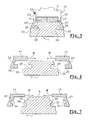
- the ski (1) has been provided at the leveling platform (8), with two longitudinal grooves (22 and 23), exactly under the upper surface of the platform (8).
- the sliding is obtained by means of two sliding portions (24 and 26).
- the two longitudinal parts (13 and 14) each comprise a lateral edge (27 and 28) substantially perpendicular to the upper plane of each of the two longitudinal parts (13 and 14) and oriented towards the gliding sole (7).
- a slide-shaped rib (24 and 26) is oriented towards the inside of the ski, and in a manner substantially parallel to the upper plane of each of the two longitudinal parts (13 and 14).
- the rib (24) of one of the two longitudinal parts (13) is oriented towards the other rib (26) of the other of the two longitudinal parts (14).
- the ribs (24 and 26) may have a length less than or equal to that of their longitudinal part (13 and 14).
- the ribs forming a slide (24 and 26) of each of the two longitudinal parts (13 and 14) are intended to cooperate by each engaging respectively in a slide or groove (29 and 30) formed in the two side faces (32 and 33) of the ski.
- the grooves (29 and 30) do not necessarily open longitudinally forwards and backwards of the ski.
- the longitudinal parts (13 and 14) each include a lateral flange (27 and 28), substantially perpendicular to the upper plane of the base, and oriented towards the gliding sole (7).
- a groove (34 and 36) In each of the two lateral edges (27 and 28) is formed a groove (34 and 36), substantially parallel to the upper plane of the base and thus of the two longitudinal parts (13 and 14).
- the grooves (34 and 36) do not necessarily open longitudinally forwards and backwards of the longitudinal parts (13 and 14).
- a protrusion forming a slide is in the form of a rib (39 and 41).
- These ribs (39 and 41) are substantially parallel to the upper plane of the platform (8) and are intended to cooperate by sliding with the respective grooves (34 and 36) of each of the two longitudinal parts (13 and 14) of the base.
- the ribs (39 and 41) may have a length less than or equal to that of the longitudinal part (13 and 14) which is fixed there.
- the ski (1) comprises, at the level of its skid zone (3), protuberances in the form of spikes or points (42), projecting transversely outwards at from and perpendicular to the two side faces (32 and 33).
- the two longitudinal parts (43 and 44) each include a lateral edge (46 and 47).
- In each of the two lateral edges (46 and 47) are formed several recesses or orifices (48). In this way, the protuberances or pins (42) will be inserted into the orifices (48), of so as to longitudinally lock each of the two longitudinal parts (43 and 44) of the base.
- protuberances (42) arranged longitudinally a few millimeters from each other, or several orifices (48) also drilled longitudinally a few millimeters from each other in the lateral flanges ( 46 and 47).
- the assembly of the two longitudinal parts (13 and 14, 43 and 44) to each other is done by means of assembly ensuring a transverse connection.
- the assembly is done by means of the front stop (9) and / or the heel piece (11), which are fixed directly on each of the two longitudinal parts (13 and 14).
- the assembly screws (49) (shown in dotted lines in Figure 4) thus allow the fastening elements (9 and 11) to be assembled on the two longitudinal parts (13, 14 and 43, 44) of the platform. form of elevation or base.
- the screws (49) drive perpendicularly, that is to say vertically, relative to the upper face (6) formed by the upper protective and decorative layer of the ski (1).
- the screws (49) of the binding elements (9 and 11) do not pass through the structure and the internal elements of the ski (1).
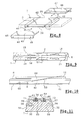
- the two longitudinal parts (13 and 14) are assembled transversely, that is to say horizontally, by means of a manual locking system (51) (see Figure 5 ).
- the locking system (51) is either an insert firmly secured to the elements of the binding (9 and 11), or is an integral part of the elements (9 and 11) of the binding.
- This locking system (51) comprises a clamp having two side jaws (52 and 53), arranged laterally with respect to the elements of the fastener (9 and 11) and with respect to each of the two longitudinal parts (13 and 14).
- one of the two jaws (53) is brought towards the other of the jaws (52) towards the median longitudinal axis of the ski by means of return in the form of an ellipsoidal spring ( 54).
- the movable jaw (53) can be grasped and manipulated by the hand of the user.
- the two jaws (52 and 53) are also wedged so as to prevent any longitudinal and vertical movement of the locking system (51).
- the two longitudinal parts (13 and 14, 43 and 44) substantially touch each other at the level of the median longitudinal axis of the ski (1).
- the two longitudinal parts (13 and 14) are separated from each other by a spacing (56).
- this spacing (56) is left free, the upper protective and decorative layer (6) is visible, which creates interesting aesthetic effects.
- the spacing (56) can also be filled with a material having elastic properties with an intrinsic damping coefficient tg ⁇ > 0.2, measured according to standard NF T 46 026 (at temperatures from -30 ° C to +10 ° C and at frequencies from 0.1 Hz to 120 Hz).
- each of these transverse parts in pairs (16 and 18, 17 and 19) is mechanically separated from each other.
- the spaces between the pairs of transverse parts (16 and 18, 17 and 19) are filled with a material with elastic properties (57) with an intrinsic damping coefficient tg ⁇ > 0.2, measured according to standard NF T 46 026 (at temperatures from -30 ° C to + 10 ° C and at frequencies from 0.1 Hz to 120 Hz).
- a lower edge (58) of the two longitudinal parts (13 and 14) is not parallel to the gliding sole (7) or to the upper protective and decorative layer (6).
- the lower edge (58) is only located in an appendage (59) belonging to the lateral rim of each of the two longitudinal parts (13 and 14), extending downwards in the direction of the edges (61).
- the lower edge (58) has, in a longitudinal plane, a non-zero angle of inclination ( ⁇ ) relative to the surface of the sliding sole (7) or relative to the surface of the upper protective and decorative layer (6) of the ski.
- This angle is between 1 ° and 20 °, and preferably between 2 ° and 5 °.
- the ski comprises two hollow zones (62) having a similar and complementary shape to the two appendages (59). These two recessed areas (62) are formed in the upper protection and decoration layer as well as in the edges (63) of the ski.
- the ski comprises at its upper protective and decorative layer two or four or a pair number of protuberances or pins (64) protruding towards the top, perpendicular to the upper face (6) of the ski (1).
- These pins (64) are regularly arranged on either side with respect to the median longitudinal axis of the ski (1).
- pins (64) cooperate with and are inserted into orifices (66) formed perpendicularly, that is to say vertically in each of the two longitudinal parts (13 and 14).
- the holes (66) are two or four in number or even and they are drilled regularly so that each one corresponds to a pin (64).
- the pins (64) are mounted so as to be slightly movable in the vertical direction.
- the pins (64) are in addition each recalled by a spring (67).
- the pin (64) and spring (67) assembly is mounted in a recess (68) formed perpendicularly, that is to say vertically in the upper protective and decorative layer of the ski (1).
- the two longitudinal parts (13 and 14) cannot move laterally or horizontally, according to the reverse movement of the arrow (M). This keeps the two longitudinal parts (13 and 14) held in the ski when the elements of the binding (9 and 11) are removed, during assembly or disassembly of these elements of the binding (9 and 11).
- the presence of the spring (67), as well as the freedom of movement of the pin (64) in its hollow (68) allows flexibility in installing and uninstalling the two longitudinal parts (13 and 14).
- the platform or the base can have a length asymmetry between the two longitudinal parts (13 and 14).
- the platform or the base may have an asymmetry in width between the two longitudinal parts (13 and 14).
- the platform or the base can have an asymmetry of the mounting means between the two longitudinal parts (13 and 14).
- the platform or the base may have an asymmetry in the number of transverse parts between the two longitudinal parts (13 and 14).
- the platform or the base can have an asymmetry of structure and materials between the two longitudinal parts (13 and 14).
Landscapes
- Footwear And Its Accessory, Manufacturing Method And Apparatuses (AREA)
- Machines For Manufacturing Corrugated Board In Mechanical Paper-Making Processes (AREA)
Applications Claiming Priority (2)
| Application Number | Priority Date | Filing Date | Title |
|---|---|---|---|
| FR0109950 | 2001-07-25 | ||
| FR0109950A FR2827787B1 (fr) | 2001-07-25 | 2001-07-25 | Dispositif support des fixations d'une chaussure et planche de glisse sur neige equipee d'un tel dispositif |
Publications (2)
| Publication Number | Publication Date |
|---|---|
| EP1279421A1 true EP1279421A1 (de) | 2003-01-29 |
| EP1279421B1 EP1279421B1 (de) | 2006-06-21 |
Family
ID=8865895
Family Applications (1)
| Application Number | Title | Priority Date | Filing Date |
|---|---|---|---|
| EP02356133A Expired - Lifetime EP1279421B1 (de) | 2001-07-25 | 2002-07-09 | Bindungsplatte und Gleitbrett mit einer solchen Einrichtung |
Country Status (4)
| Country | Link |
|---|---|
| EP (1) | EP1279421B1 (de) |
| AT (1) | ATE330677T1 (de) |
| DE (1) | DE60212506T2 (de) |
| FR (1) | FR2827787B1 (de) |
Cited By (3)
| Publication number | Priority date | Publication date | Assignee | Title |
|---|---|---|---|---|
| EP1366785A1 (de) * | 2002-05-27 | 2003-12-03 | Head Technology GmbH | Ski, Verfahren zur Montage einer Skibindung an dem Ski und Verfahren zur Herstellung des Skis |
| WO2004078286A1 (de) * | 2003-03-07 | 2004-09-16 | Tyrolia Technology Gmbh | Gleitbrett, insbesondere ski |
| EP1479416A1 (de) * | 2003-05-21 | 2004-11-24 | Skis Rossignol S.A. | Schneegleitbrett mit einer Aussen Dekorations- und Schutzeinrichtung sowie Herstellungsverfahren |
Citations (5)
| Publication number | Priority date | Publication date | Assignee | Title |
|---|---|---|---|---|
| FR2194458A1 (de) | 1972-06-30 | 1974-03-01 | Nippon Musical Instruments Mfg | |
| EP0383104A2 (de) | 1989-02-15 | 1990-08-22 | HTM Sport- und Freizeitgeräte Aktiengesellschaft | Ski |
| WO1991004770A1 (en) | 1989-09-29 | 1991-04-18 | Sutherland Robert L | Short, wide ski and binding |
| DE4100327A1 (de) * | 1990-01-18 | 1991-07-25 | Salomon Sa | Montagevorrichtung eines schuhs auf einem ski |
| DE29511954U1 (de) | 1995-07-25 | 1995-09-28 | Wertz, Dietrich, Dipl.-Ing., 57555 Mudersbach | Grund-/Trägerplatte für Skibindungen |
-
2001
- 2001-07-25 FR FR0109950A patent/FR2827787B1/fr not_active Expired - Fee Related
-
2002
- 2002-07-09 EP EP02356133A patent/EP1279421B1/de not_active Expired - Lifetime
- 2002-07-09 AT AT02356133T patent/ATE330677T1/de not_active IP Right Cessation
- 2002-07-09 DE DE60212506T patent/DE60212506T2/de not_active Expired - Lifetime
Patent Citations (6)
| Publication number | Priority date | Publication date | Assignee | Title |
|---|---|---|---|---|
| FR2194458A1 (de) | 1972-06-30 | 1974-03-01 | Nippon Musical Instruments Mfg | |
| US3899186A (en) * | 1972-06-30 | 1975-08-12 | Nippon Musical Instruments Mfg | Ski having base blocks for securing bindings |
| EP0383104A2 (de) | 1989-02-15 | 1990-08-22 | HTM Sport- und Freizeitgeräte Aktiengesellschaft | Ski |
| WO1991004770A1 (en) | 1989-09-29 | 1991-04-18 | Sutherland Robert L | Short, wide ski and binding |
| DE4100327A1 (de) * | 1990-01-18 | 1991-07-25 | Salomon Sa | Montagevorrichtung eines schuhs auf einem ski |
| DE29511954U1 (de) | 1995-07-25 | 1995-09-28 | Wertz, Dietrich, Dipl.-Ing., 57555 Mudersbach | Grund-/Trägerplatte für Skibindungen |
Cited By (8)
| Publication number | Priority date | Publication date | Assignee | Title |
|---|---|---|---|---|
| EP1366785A1 (de) * | 2002-05-27 | 2003-12-03 | Head Technology GmbH | Ski, Verfahren zur Montage einer Skibindung an dem Ski und Verfahren zur Herstellung des Skis |
| WO2004078286A1 (de) * | 2003-03-07 | 2004-09-16 | Tyrolia Technology Gmbh | Gleitbrett, insbesondere ski |
| AT500252A1 (de) * | 2003-03-07 | 2005-11-15 | Tyrolia Technology Gmbh | Gleitbrett, insbesondere ski, und verfahren zur herstellung |
| AT500252B1 (de) * | 2003-03-07 | 2008-12-15 | Tyrolia Technology Gmbh | Gleitbrett, insbesondere ski |
| US7497460B2 (en) | 2003-03-07 | 2009-03-03 | Tyrolia Technology Gmbh | Sliding board, particularly a ski |
| EP1479416A1 (de) * | 2003-05-21 | 2004-11-24 | Skis Rossignol S.A. | Schneegleitbrett mit einer Aussen Dekorations- und Schutzeinrichtung sowie Herstellungsverfahren |
| FR2855066A1 (fr) * | 2003-05-21 | 2004-11-26 | Rossignol Sa | Planche de glisse sur neige avec un ensemble exterieur de decoration et de protection et procede de fabrication |
| US7261791B2 (en) | 2003-05-21 | 2007-08-28 | Skis Rossignol S.A. | Board for gliding over snow with a decorative and protective exterior assembly, and manufacturing method |
Also Published As
| Publication number | Publication date |
|---|---|
| EP1279421B1 (de) | 2006-06-21 |
| ATE330677T1 (de) | 2006-07-15 |
| DE60212506T2 (de) | 2006-11-16 |
| FR2827787A1 (fr) | 2003-01-31 |
| FR2827787B1 (fr) | 2003-11-07 |
| DE60212506D1 (de) | 2006-08-03 |
Similar Documents
| Publication | Publication Date | Title |
|---|---|---|
| EP0744195B1 (de) | Snowboard mit Tragplatte zum Erhöhen der Skibindung | |
| EP1308190B1 (de) | Trägerplatte und ein Snowboard mit einer solchen Trägerplatte | |
| EP0650385B1 (de) | Rückhaltevorrichtung für einen snowboardschuh | |
| EP1563876A1 (de) | Langlaufski | |
| EP1277500B1 (de) | Trägerplatte und Gleitbrett mit solch einer Trägerplatte | |
| EP1329246B1 (de) | Verbesserte Kupplung eines Stiefels an ein Snowboard | |
| EP1829587B1 (de) | Anschlussvorrichtung für ein Snowboard | |
| FR2810251A1 (fr) | Ski alpin | |
| EP1279421B1 (de) | Bindungsplatte und Gleitbrett mit einer solchen Einrichtung | |
| EP3693065A1 (de) | Montageanordnung zum festen verbinden eines schuhwerks auf einem snowboard | |
| EP1234604B1 (de) | Trägerplatte für ein Snowboard | |
| EP0956886A1 (de) | Trägerplatte zwischen Schuh und Snowboard | |
| EP1508352A1 (de) | Snowboardbindung | |
| EP1013317B1 (de) | Schneegleitbrett | |
| FR2685313A1 (fr) | Dispositif de fixation d'un patin de guidage de la partie inferieure d'une porte coulissante d'ascenseur. | |
| FR2755025A1 (fr) | Dispositif de liaison entre une planche a usage sportif, notamment une planche a neige, et une fixation de chaussure | |
| EP0820791A1 (de) | Vorrichtung zur Fortbewegung auf Schnee | |
| EP1424108A1 (de) | Schneegleitbrett mit seitliche Abstützungplatte | |
| FR2809634A1 (fr) | Dispositif de rehaussement destine a etre monte sur une planche de glisse | |
| EP1673147B1 (de) | Langlaufskisystem mit einer direktlager-seitenfläche | |
| WO2002085473A1 (fr) | Dispositif de montage, demontage rapides d'une fixation de ski sur un ski | |
| EP1736212B1 (de) | Verbesserung für Schneegleibrett | |
| FR2815879A1 (fr) | Plate-forme de rehaussement destinee a etre ancree sur un ski | |
| EP1481713B1 (de) | Plattform zur Erhöhung einer Snowboardbindung | |
| EP1479417B1 (de) | Snowboardbindung |
Legal Events
| Date | Code | Title | Description |
|---|---|---|---|
| PUAI | Public reference made under article 153(3) epc to a published international application that has entered the european phase |
Free format text: ORIGINAL CODE: 0009012 |
|
| AK | Designated contracting states |
Designated state(s): AT BE BG CH CY CZ DE DK EE ES FI FR GB GR IE IT LI LU MC NL PT SE SK TR |
|
| AX | Request for extension of the european patent |
Extension state: AL LT LV MK RO SI |
|
| 17P | Request for examination filed |
Effective date: 20030331 |
|
| AKX | Designation fees paid |
Designated state(s): AT DE FR |
|
| 17Q | First examination report despatched |
Effective date: 20050705 |
|
| GRAP | Despatch of communication of intention to grant a patent |
Free format text: ORIGINAL CODE: EPIDOSNIGR1 |
|
| GRAS | Grant fee paid |
Free format text: ORIGINAL CODE: EPIDOSNIGR3 |
|
| GRAA | (expected) grant |
Free format text: ORIGINAL CODE: 0009210 |
|
| RAP1 | Party data changed (applicant data changed or rights of an application transferred) |
Owner name: SKIS ROSSIGNOL |
|
| AK | Designated contracting states |
Kind code of ref document: B1 Designated state(s): AT DE FR |
|
| PGFP | Annual fee paid to national office [announced via postgrant information from national office to epo] |
Ref country code: FR Payment date: 20060728 Year of fee payment: 5 |
|
| REF | Corresponds to: |
Ref document number: 60212506 Country of ref document: DE Date of ref document: 20060803 Kind code of ref document: P |
|
| PLBE | No opposition filed within time limit |
Free format text: ORIGINAL CODE: 0009261 |
|
| STAA | Information on the status of an ep patent application or granted ep patent |
Free format text: STATUS: NO OPPOSITION FILED WITHIN TIME LIMIT |
|
| 26N | No opposition filed |
Effective date: 20070322 |
|
| PGFP | Annual fee paid to national office [announced via postgrant information from national office to epo] |
Ref country code: AT Payment date: 20070618 Year of fee payment: 6 |
|
| REG | Reference to a national code |
Ref country code: FR Ref legal event code: ST Effective date: 20080331 |
|
| PG25 | Lapsed in a contracting state [announced via postgrant information from national office to epo] |
Ref country code: FR Free format text: LAPSE BECAUSE OF NON-PAYMENT OF DUE FEES Effective date: 20070731 |
|
| PG25 | Lapsed in a contracting state [announced via postgrant information from national office to epo] |
Ref country code: AT Free format text: LAPSE BECAUSE OF NON-PAYMENT OF DUE FEES Effective date: 20080709 |
|
| PGFP | Annual fee paid to national office [announced via postgrant information from national office to epo] |
Ref country code: DE Payment date: 20110713 Year of fee payment: 10 |
|
| PG25 | Lapsed in a contracting state [announced via postgrant information from national office to epo] |
Ref country code: DE Free format text: LAPSE BECAUSE OF NON-PAYMENT OF DUE FEES Effective date: 20130201 |
|
| REG | Reference to a national code |
Ref country code: DE Ref legal event code: R119 Ref document number: 60212506 Country of ref document: DE Effective date: 20130201 |