EP1279439A2 - Collecteur électrique de poussière, méthode de collecte de poussière et soufflerie les utilisant - Google Patents
Collecteur électrique de poussière, méthode de collecte de poussière et soufflerie les utilisant Download PDFInfo
- Publication number
- EP1279439A2 EP1279439A2 EP02015169A EP02015169A EP1279439A2 EP 1279439 A2 EP1279439 A2 EP 1279439A2 EP 02015169 A EP02015169 A EP 02015169A EP 02015169 A EP02015169 A EP 02015169A EP 1279439 A2 EP1279439 A2 EP 1279439A2
- Authority
- EP
- European Patent Office
- Prior art keywords
- dust collecting
- dust
- acoustic wave
- dust collector
- section
- Prior art date
- Legal status (The legal status is an assumption and is not a legal conclusion. Google has not performed a legal analysis and makes no representation as to the accuracy of the status listed.)
- Granted
Links
Images


Classifications
-
- A—HUMAN NECESSITIES
- A01—AGRICULTURE; FORESTRY; ANIMAL HUSBANDRY; HUNTING; TRAPPING; FISHING
- A01G—HORTICULTURE; CULTIVATION OF VEGETABLES, FLOWERS, RICE, FRUIT, VINES, HOPS OR SEAWEED; FORESTRY; WATERING
- A01G13/00—Protection of plants
- A01G13/30—Ground coverings
- A01G13/37—Arrangements for laying out or removing ground coverings
-
- B—PERFORMING OPERATIONS; TRANSPORTING
- B03—SEPARATION OF SOLID MATERIALS USING LIQUIDS OR USING PNEUMATIC TABLES OR JIGS; MAGNETIC OR ELECTROSTATIC SEPARATION OF SOLID MATERIALS FROM SOLID MATERIALS OR FLUIDS; SEPARATION BY HIGH-VOLTAGE ELECTRIC FIELDS
- B03C—MAGNETIC OR ELECTROSTATIC SEPARATION OF SOLID MATERIALS FROM SOLID MATERIALS OR FLUIDS; SEPARATION BY HIGH-VOLTAGE ELECTRIC FIELDS
- B03C3/00—Separating dispersed particles from gases or vapour, e.g. air, by electrostatic effect
- B03C3/32—Transportable units, e.g. for cleaning room air
-
- A—HUMAN NECESSITIES
- A01—AGRICULTURE; FORESTRY; ANIMAL HUSBANDRY; HUNTING; TRAPPING; FISHING
- A01G—HORTICULTURE; CULTIVATION OF VEGETABLES, FLOWERS, RICE, FRUIT, VINES, HOPS OR SEAWEED; FORESTRY; WATERING
- A01G13/00—Protection of plants
- A01G13/30—Ground coverings
- A01G13/32—Mats; Nets; Sheets or films
- A01G13/33—Sheets or films
-
- B—PERFORMING OPERATIONS; TRANSPORTING
- B03—SEPARATION OF SOLID MATERIALS USING LIQUIDS OR USING PNEUMATIC TABLES OR JIGS; MAGNETIC OR ELECTROSTATIC SEPARATION OF SOLID MATERIALS FROM SOLID MATERIALS OR FLUIDS; SEPARATION BY HIGH-VOLTAGE ELECTRIC FIELDS
- B03C—MAGNETIC OR ELECTROSTATIC SEPARATION OF SOLID MATERIALS FROM SOLID MATERIALS OR FLUIDS; SEPARATION BY HIGH-VOLTAGE ELECTRIC FIELDS
- B03C3/00—Separating dispersed particles from gases or vapour, e.g. air, by electrostatic effect
- B03C3/01—Pretreatment of the gases prior to electrostatic precipitation
- B03C3/016—Pretreatment of the gases prior to electrostatic precipitation by acoustic or electromagnetic energy, e.g. ultraviolet light
-
- B—PERFORMING OPERATIONS; TRANSPORTING
- B03—SEPARATION OF SOLID MATERIALS USING LIQUIDS OR USING PNEUMATIC TABLES OR JIGS; MAGNETIC OR ELECTROSTATIC SEPARATION OF SOLID MATERIALS FROM SOLID MATERIALS OR FLUIDS; SEPARATION BY HIGH-VOLTAGE ELECTRIC FIELDS
- B03C—MAGNETIC OR ELECTROSTATIC SEPARATION OF SOLID MATERIALS FROM SOLID MATERIALS OR FLUIDS; SEPARATION BY HIGH-VOLTAGE ELECTRIC FIELDS
- B03C3/00—Separating dispersed particles from gases or vapour, e.g. air, by electrostatic effect
- B03C3/02—Plant or installations having external electricity supply
- B03C3/04—Plant or installations having external electricity supply dry type
- B03C3/14—Plant or installations having external electricity supply dry type characterised by the additional use of mechanical effects, e.g. gravity
- B03C3/155—Filtration
Definitions
- the present invention relates to an electric dust collector that collects dust in air, more particularly relates to a highly efficient electric dust collector that makes use of corona discharge and is to be employed in air conditioners or air purifiers.
- the present invention also relates to a method of collecting dust using the same dust collector.
- An electric dust collector comprises mainly a charging section that generates corona discharge for charging dust and a dust collecting section that collects the charged dust. Those two elements are integrated into one unit and disposed at an air sucking port of air conditioners , air purifiers or similar apparatus.
- FIG. 7 shows this dust collector, which collects dust in the following manner: A voltage is applied between discharge electrode 503 and counter electrode 504, both the electrodes forming charging section 501, thereby generating corona discharge. This corona discharge charges dust in air blown there. Then dust collecting section 502, formed of grounding electrode 505 disposed downstream of blowing path and high-voltage electrode 506, collects electrically the charged dust. Discharge electrode 503 is formed of linear wires or needles, and spaced away at a given distance from counter electrode 504. Dust collecting section 502 is constructed to collect electrically dust; however, there is another instance, i.e., a charged filter is disposed for collecting dust.
- the present invention addresses the problems discussed above and aims to provide an electric dust collector that charges dust efficiently with less power consumption and yet increases a dust collection rate.
- the present invention also aims to provide a blower employing the same electric dust collector.
- the dust collector of the present invention comprises the following elements:
- the dust collector of the present invention has another structure that allows the discharge electrode of the charging section to be vibrated.
- the charging probability of dust particles in air is increased by enlarging the charging area, and the collision probability of dust particles is increased so that cohesion of dust particles can make a particle diameter easy to collect.
- a dust collector of a higher dust collection rate is obtainable.
- Fig. 1 is an exploded perspective view illustrating an example of a structure of an electric dust collector
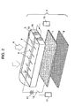
- Fig. 2 is an exploded perspective view illustrating a structure of a dust collecting unit of an electric dust collector in accordance with the first exemplary embodiment.
- electric dust collector 1 includes dust collecting unit 2 and main unit 3, in which dust collecting unit 2 is accommodated. Dust collector 1 is disposed, e.g., in an indoor unit of air conditioners. When interior air 4 passes through dust collecting unit 2, dust particles included in interior air 4 are collected, and air 4 undergoes a heat exchanger of the indoor unit, then blown out into the room again.
- dust collecting unit 2 comprises housing 5 made of resin material molded, discharge electrode 6, counter electrode 7 and dust filter 8.
- Housing 5 shapes in substantially a rectangle for enlarging a pass-through area of interior air 4.
- a plurality of needle-like discharge electrodes 6 are supported by supporter 9.
- Sheet-like counter electrode 7 having an opening through which the interior air passes is fixed to housing 5 and is apart from discharge electrode 6 at a given distance.
- Dust filter 8 is disposed on a downstream side of interior air 4 of counter electrode 7, and is detachable from dust collecting unit 2. When dust adheres to filter 8, it can be detached for cleaning.
- the plurality of discharging electrodes 6 are coupled with a common electrode (not shown) disposed within supporter 9.
- DC power supply 10 outside the dust collecting unit applies a voltage between discharge electrodes 6 and counter electrode 7.
- the voltage application is controlled by switch 12 which is opened or closed by a signal from controller 11.
- discharge electrodes 6 and counter electrode 7 constitute a charging section, and dust filter 8 forms a dust collecting section.
- a discharge electrode and a counter electrode constitute a charging section
- a grounding electrode and a high voltage electrode constitute a dust collecting section.
- the counter electrode and the grounding electrode are integrated into one unit, and a voltage of this part is used as a common.
- the counter electrode and the dust collecting section can be integrated into one unit.
- discharge electrode 6 (negative electrode) and counter electrode 7 (positive electrode) that functions also as the dust collecting section work together to collect negatively charged dust particles, and the dust particles are collected by the positive counter electrode 7 (dust collecting section).
- needle-like discharge electrodes 6 are used; however, a linear wire made of tungsten is also usable instead of needle-like member. A voltage is applied so that discharge electrodes 6 become negative; however, the voltage can be applied in the other way so that the discharge electrode can be positive.
- dc power supply 10 applies a voltage between discharge electrode 6 and counter electrode 7. If a dc voltage of several kilo-volts is applied therebetween, corona discharge occurs between the two electrodes, so that positive or negative electric charges are generated. Dust particles passing there are thus charged.
- An electret filter charged positive or negative, or charged partially positive and partially negative is used as a dust filter 8 of dust collecting unit 2. As a result, the dust particles charged in corona discharging area are absorbed by filter 8 and collected.
- the electret filter charged per se is used as dust filter 8; however, when a diameter of dust particles coherent with each other is greater, a non-charged filter, i.e., not a regular one, can be used.
- dust filter is disposed at the lowest part of downstream of blowing direction of dust collecting unit 2.
- counter electrode 7 is a grounding electrode
- dust filter 8 is preferably disposed between discharge electrodes 6 and counter electrode 7 so that the dust particles keep being charged and are collected by filter 8.
- corona discharge occurs in a direction substantially parallel to the flow of interior air 4; however, if the corona discharge occurs in a vertical direction to the flow of interior air 4, a similar result of collecting dust can be obtained.
- an acoustic wave is irradiated to at least a part of discharge portion of the charging section.
- acoustic wave generating means 14 is provided to side face 13 of housing 5, where an opening (not shown) is provided to side face 13.
- Acoustic wave controller 15 for controlling acoustic wave generating means 14 is provided outside dust collecting unit 2.
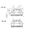
- Fig. 3 is a lateral view of dust collecting unit 2, shown in Fig. 2, viewed from acoustic wave generating means 14.
- the present invention irradiates acoustic waves for enlarging the discharging area with low power consumption.
- the acoustic waves can enlarge the discharging area because charged particles in the area vibrate to diffuse.
- a piezoelectric element is used as acoustic wave generating means 14.
- An area where acoustic waves are irradiated is described with reference to Fig. 3.
- corona discharge 17 occurs from tip 16 of needle-like discharge electrode 6 and extends forming a conical shape in a space between the two electrodes.
- acoustic wave generating means 14 is disposed so that it can irradiate acoustic waves between the two electrodes.
- the position from which the acoustic waves are irradiated is preferably as close as possible to discharge electrode 6, because diffusion of charged particles at the root of the discharge can further diffuse the charged particles into an extensive area before they arrive at counter electrode 7.
- An instance is shown in Fig. 3B, which proves that irradiation to an area including discharge electrode 6 results in more effective expansion of the discharge.
- the acoustic waves can be irradiated to, e.g., discharge electrode 6 or the space between discharge electrodes 6 and counter electrode 7 from outside of dust collecting unit 2 in a slanting direction.
- an acoustic wave is irradiated substantially in a vertical direction to an electric field that generates the discharge, so that the acoustic wave can be focused on a specific place with ease.
- the irradiation can be in a parallel direction to the electric field with a similar advantage.
- acoustic wave generating means 14 are disposed on side wall 13 all around, so that acoustic waves can be irradiated to entire discharging area.
- the acoustic waves can be irradiated to the corona discharge between numbers of discharge electrodes 6 and counter electrode 7, and the more effective result can be expected.
- Acoustic wave generating means 14 is controlled the intensity of its acoustic waves, frequency, and on/off by acoustic-wave controller 15.
- the frequency is preferably over 20 kHz (ultrasonic wave) which is out of human audible range, so that a user does not feel unpleasantly or misunderstand the frequency as a malfunction. If a user has a pet such as dogs or cats, they can hear a frequency over 20 kHz. Thus a higher frequency is preferably for those pets. In this case, an appropriate frequency is optionally selectable depending on a user's condition.
- a piezoelectric element is used as acoustic wave generating means 14; however, a speaker, a sonar, or a crystal oscillator that generates vibrations can be used instead.
- An appropriate device can be selected depending on conditions such as directivity of originating acoustic waves, a cost and a structure of the dust collecting unit, an area size to be irradiated, or a required energy intensity of acoustic waves.
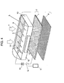
- reflector 19 that reflects the acoustic wave originated by acoustic wave generating means 14 is provided facing inward of dust collecting unit 2 on at least a part of side wall 18 of housing 5.
- the side wall here means a wall of housing 5 that is one of the elements forming dust collecting unit 2, and the acoustic waves are irradiated toward side wall 18.
- reflector 19 provided on side wall 18 is placed such that the direction of originating acoustic wave faces reflector 19.
- reflector 19 can be provided on a side wall of main unit 3, shown in Fig. 1, which accommodates dust collecting unit 2. In this case, an opening is prepared on side wall 18 corresponding to the reflector provided to main unit 3.
- This structure allows an acoustic wave arriving at reflector 19 to reflect and diffuse, so that this acoustic wave is irradiated to the corona discharge again, which can enhance diffusion of the corona discharge. If a directivity of an acoustic wave from acoustic wave generating means 14 disposed on side wall 18 is low, another reflector 19 is needed on a place other than side wall 18. Reflector 19 is preferably made of non-conductive material or low conductive material, so that it does not adversely affect a direction of generating the corona discharge.
- a buffering member (not shown) that absorbs acoustic waves or a reflection member can be prepared if necessary, so that the acoustic wave is prevented from diffusing in an unnecessary direction to adversely affect other elements.
- acoustic wave generating means 14 is disposed to side wall 13 on a shorter side of rectangular dust-collecting unit 2. However, as shown in Fig. 4, it can be disposed at a center on a longer side, thereby irradiating acoustic waves both right and left of the longer side.
- the acoustic wave is irradiated to the charging section or both the longer sides of the dust collecting section, so that the irradiation distance becomes short and the corona discharge can be diffused by a greater energy of the acoustic wave.
- This structure enlarges an area of corona discharge generated in the charging section, and increases a probability of collision between particles thereby accelerating cohesion of those particles. As a result, a dust collection rate of the electric dust collector can be improved.
- the charging section and acoustic wave generating means 14 are electrically coupled with power supply 10 and controller 11. Therefore, if dust collecting section 8 is detachable from main unit 3 of dust collector 1, a user can maintain dust collecting section 8 with ease. Further, dust-collecting unit 2 formed of the charging section and the dust collecting section is detachable from main unit 3, and dust collecting section 3 is detachable from unit 2.
- This structure allows a user to detach unit 2 from dust collector 1 mounted to an indoor unit of an air conditioner, and the user further can detach the dust collecting section from dust-collecting unit 2 for maintenance. Thus an electric dust collector with a superb maintainability is obtainable.
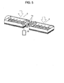
- Fig. 5 is a perspective view illustrating a structure of dust collecting unit 2 of an electric dust collector in accordance with the second embodiment.
- dust collecting unit 2 is divided into plural parts as shown in Fig. 5 in order to enlarge an interior-air sucking area as well as improve maintainability of the dust collecting unit.
- the second embodiment allows acoustic wave generating means to irradiate acoustic waves to such plural dust-collecting units 2.
- acoustic wave generating means 14 is placed between both the dust collecting units 2 so that it can irradiate acoustic waves to corona discharges generated in both units 2.
- Acoustic wave generating means 14 can be integrated into unit 2 or can be placed independently of unit 2. It can be anyway placed or formed such that it can irradiate acoustic waves to at least a part of a discharge portion.
- This structure allows one single acoustic wave generating means 14 to irradiate acoustic waves to two dust-collecting units 2 disposed to sandwich the acoustic wave generating means.
- a number of components can be reduced, and electric wires can be routed to only one place, so that a smaller space is required for installing.
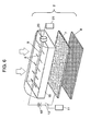
- Fig. 6 is a perspective view illustrating a structure of dust collecting unit 2 in accordance with the third embodiment.
- the present invention employs those electric dust collectors previously demonstrated in a blower, whereby a blower of a high dust-collection rate is obtainable, and mildew in a blowing path is suppressed. Employment of such a blowing path in air conditioners or air purifiers realizes more hygienic and comfortable air conditioned environments.
- the electric dust collector of the present invention includes a charging section, a dust collecting section, and acoustic wave generating means that irradiates acoustic waves to at least a part of a discharge portion of the charging section.
- This structure allows irradiation of acoustic wave to a corona discharging area, so that an area where the corona discharge is generated in the charging section can be enlarged, and at the same time, a probability of collision between particles is increased, which accelerates cohesion of the particles.
- a dust collection rate can be increased, and a hygienic and comfortable air conditioner or air purifier is obtainable.
Landscapes
- Health & Medical Sciences (AREA)
- General Health & Medical Sciences (AREA)
- Toxicology (AREA)
- Life Sciences & Earth Sciences (AREA)
- Environmental Sciences (AREA)
- Physics & Mathematics (AREA)
- Acoustics & Sound (AREA)
- Electromagnetism (AREA)
- Electrostatic Separation (AREA)
- Air Filters, Heat-Exchange Apparatuses, And Housings Of Air-Conditioning Units (AREA)
Applications Claiming Priority (2)
| Application Number | Priority Date | Filing Date | Title |
|---|---|---|---|
| JP2001221133 | 2001-07-23 | ||
| JP2001221133 | 2001-07-23 |
Publications (3)
| Publication Number | Publication Date |
|---|---|
| EP1279439A2 true EP1279439A2 (fr) | 2003-01-29 |
| EP1279439A3 EP1279439A3 (fr) | 2005-11-23 |
| EP1279439B1 EP1279439B1 (fr) | 2010-09-01 |
Family
ID=19054850
Family Applications (1)
| Application Number | Title | Priority Date | Filing Date |
|---|---|---|---|
| EP02015169A Expired - Lifetime EP1279439B1 (fr) | 2001-07-23 | 2002-07-08 | Collecteur électrique de poussière, méthode de collecte de poussière et soufflerie les utilisant |
Country Status (5)
| Country | Link |
|---|---|
| EP (1) | EP1279439B1 (fr) |
| KR (2) | KR100613931B1 (fr) |
| CN (3) | CN1600443A (fr) |
| ES (1) | ES2349857T3 (fr) |
| MY (1) | MY129377A (fr) |
Cited By (8)
| Publication number | Priority date | Publication date | Assignee | Title |
|---|---|---|---|---|
| EP1547693A4 (fr) * | 2003-06-05 | 2009-02-11 | Daikin Ind Ltd | Appareil de decharge et appareil de purification d'air |
| EP3048380A4 (fr) * | 2013-09-16 | 2016-08-10 | Shenzhen Tongsheng Green Technology Co Ltd | Purificateur d'air par ions négatifs |
| EP3048381A4 (fr) * | 2013-09-16 | 2016-08-10 | Shenzhen Tongsheng Green Technology Co Ltd | Purificateur d'air à ions négatifs |
| CN106288003A (zh) * | 2016-08-02 | 2017-01-04 | 王彦宸 | 空气净化器及空气净化方法 |
| EP3089292B1 (fr) * | 2013-12-27 | 2020-05-27 | Daikin Industries, Ltd. | Dispositif de décharge et dispositif de traitement d'air |
| WO2020104488A1 (fr) * | 2018-11-19 | 2020-05-28 | Blueair Cabin Air Ab | Unité d'ionisation servant à charger négativement des particules en suspension dans l'air présentes dans un flux d'air, dispositif de purification d'air et dispositif adapté à un véhicule |
| US10933431B2 (en) | 2015-11-20 | 2021-03-02 | Samsung Electronics Co., Ltd. | Electric dust collection device and manufacturing method therefor |
| CN120789913A (zh) * | 2025-08-29 | 2025-10-17 | 山东金孚环境工程有限公司 | 一种等离子体有机废气催化净化系统 |
Families Citing this family (17)
| Publication number | Priority date | Publication date | Assignee | Title |
|---|---|---|---|---|
| EP2033564A4 (fr) * | 2006-06-22 | 2012-08-01 | Sharp Kk | Conduit de concentration de la poussière, élément d'appel des charges, tube en résine d'accumulation de charges par frottement, aspirateur électrique |
| CN103025434A (zh) * | 2010-06-02 | 2013-04-03 | 三菱重工机电系统株式会社 | 集尘装置的运行方法以及集尘装置 |
| CN102641627A (zh) * | 2012-03-31 | 2012-08-22 | 太仓市金鹿电镀有限公司 | 一种空气净化装置 |
| WO2013152690A1 (fr) * | 2012-04-12 | 2013-10-17 | Sun Maohua | Dispositif de purification d'air et procédé de collecte de poussière par l'utilisation d'une caractéristique d'électret de matériau |
| CN102974461B (zh) * | 2012-04-12 | 2015-09-02 | 孙茂华 | 利用材料驻极体特性集尘的空气净化装置和空气净化方法 |
| CN103047669B (zh) * | 2012-12-19 | 2016-05-18 | 华电电力科学研究院 | 一种烟道内嵌式声电联合聚凝器 |
| WO2014122756A1 (fr) * | 2013-02-07 | 2014-08-14 | 三菱重工メカトロシステムズ株式会社 | Collecteur de poussière, procédé de sélection d'électrode pour collecteur de poussière, et procédé de collecte de poussière |
| CN104226477A (zh) * | 2013-06-18 | 2014-12-24 | 珠海格力电器股份有限公司 | 空气净化器及其净化方法 |
| CN105080258B (zh) * | 2014-04-15 | 2017-05-10 | 纳米新能源(唐山)有限责任公司 | 气体净化装置及应用该气体净化装置的车辆空气净化系统 |
| CN105983486B (zh) * | 2015-01-28 | 2018-11-20 | 上海思奈环保科技有限公司 | 一种空气净化高压离子驻极体净化装置及空气净化装置 |
| CN104613546A (zh) * | 2015-02-09 | 2015-05-13 | 绍兴大科环保科技有限公司 | 一种中央供氧空气净化空调 |
| CN104923403B (zh) * | 2015-06-29 | 2018-03-16 | 浙江大学 | 声波联合电场作用脱除细颗粒物的装置及其方法 |
| KR101930069B1 (ko) * | 2016-10-25 | 2018-12-17 | 한국기계연구원 | 미세먼지 및 유해가스 동시처리 장치 및 이를 이용한 미세먼지와 유해가스의 동시처리 방법 |
| CN107804292B (zh) * | 2017-09-30 | 2023-02-14 | 深圳市俯仰科技有限公司 | 场效应洗车器 |
| CN112076892A (zh) * | 2019-06-14 | 2020-12-15 | 釜山大学校产学协力团 | 电除尘装置及采用该装置的空气净化装置 |
| CN113905801A (zh) * | 2019-06-28 | 2022-01-07 | 韩国生产技术研究院 | 微细颗粒聚集方法及装置 |
| CN112657677B (zh) * | 2020-12-11 | 2023-08-01 | 常州大学 | 一种声电强化细颗粒凝并的除尘装置 |
Citations (7)
| Publication number | Priority date | Publication date | Assignee | Title |
|---|---|---|---|---|
| GB118342A (en) | 1917-09-05 | 1918-08-29 | Hubert Hagens | An Improved Piston for use in Internal Combustion Engines. |
| GB1369142A (en) | 1971-03-26 | 1974-10-02 | Masuda S | Apparatus for precipitating particles from a gas laden with such particles |
| US3976448A (en) | 1972-04-20 | 1976-08-24 | Lin Eng Corporation | Electrostatic and sonic gas processing apparatus |
| US4671808A (en) | 1984-11-05 | 1987-06-09 | Flakt Ab | Arrangement for supporting a plurality of discharge electrodes, and a discharge electrode suited to the arrangement |
| US5332425A (en) | 1993-02-22 | 1994-07-26 | Hung Hsing Electric Co., Ltd. | Air purifier |
| EP0804966A1 (fr) | 1996-04-30 | 1997-11-05 | Commissariat A L'energie Atomique | Filtre électrostatique à procédé de décolmatage rapide sans rupture de confinement |
| JPH11151452A (ja) | 1997-11-20 | 1999-06-08 | Midori Anzen Co Ltd | 電気集塵装置 |
-
2002
- 2002-07-05 MY MYPI20022564A patent/MY129377A/en unknown
- 2002-07-08 EP EP02015169A patent/EP1279439B1/fr not_active Expired - Lifetime
- 2002-07-08 ES ES02015169T patent/ES2349857T3/es not_active Expired - Lifetime
- 2002-07-19 CN CNA2004100809794A patent/CN1600443A/zh active Pending
- 2002-07-19 CN CN02241580U patent/CN2573904Y/zh not_active Expired - Lifetime
- 2002-07-19 CN CNB021263582A patent/CN1199024C/zh not_active Expired - Fee Related
- 2002-07-22 KR KR1020020042863A patent/KR100613931B1/ko not_active Expired - Fee Related
-
2005
- 2005-01-19 KR KR1020050005163A patent/KR100555994B1/ko not_active Expired - Fee Related
Patent Citations (7)
| Publication number | Priority date | Publication date | Assignee | Title |
|---|---|---|---|---|
| GB118342A (en) | 1917-09-05 | 1918-08-29 | Hubert Hagens | An Improved Piston for use in Internal Combustion Engines. |
| GB1369142A (en) | 1971-03-26 | 1974-10-02 | Masuda S | Apparatus for precipitating particles from a gas laden with such particles |
| US3976448A (en) | 1972-04-20 | 1976-08-24 | Lin Eng Corporation | Electrostatic and sonic gas processing apparatus |
| US4671808A (en) | 1984-11-05 | 1987-06-09 | Flakt Ab | Arrangement for supporting a plurality of discharge electrodes, and a discharge electrode suited to the arrangement |
| US5332425A (en) | 1993-02-22 | 1994-07-26 | Hung Hsing Electric Co., Ltd. | Air purifier |
| EP0804966A1 (fr) | 1996-04-30 | 1997-11-05 | Commissariat A L'energie Atomique | Filtre électrostatique à procédé de décolmatage rapide sans rupture de confinement |
| JPH11151452A (ja) | 1997-11-20 | 1999-06-08 | Midori Anzen Co Ltd | 電気集塵装置 |
Cited By (8)
| Publication number | Priority date | Publication date | Assignee | Title |
|---|---|---|---|---|
| EP1547693A4 (fr) * | 2003-06-05 | 2009-02-11 | Daikin Ind Ltd | Appareil de decharge et appareil de purification d'air |
| EP3048380A4 (fr) * | 2013-09-16 | 2016-08-10 | Shenzhen Tongsheng Green Technology Co Ltd | Purificateur d'air par ions négatifs |
| EP3048381A4 (fr) * | 2013-09-16 | 2016-08-10 | Shenzhen Tongsheng Green Technology Co Ltd | Purificateur d'air à ions négatifs |
| EP3089292B1 (fr) * | 2013-12-27 | 2020-05-27 | Daikin Industries, Ltd. | Dispositif de décharge et dispositif de traitement d'air |
| US10933431B2 (en) | 2015-11-20 | 2021-03-02 | Samsung Electronics Co., Ltd. | Electric dust collection device and manufacturing method therefor |
| CN106288003A (zh) * | 2016-08-02 | 2017-01-04 | 王彦宸 | 空气净化器及空气净化方法 |
| WO2020104488A1 (fr) * | 2018-11-19 | 2020-05-28 | Blueair Cabin Air Ab | Unité d'ionisation servant à charger négativement des particules en suspension dans l'air présentes dans un flux d'air, dispositif de purification d'air et dispositif adapté à un véhicule |
| CN120789913A (zh) * | 2025-08-29 | 2025-10-17 | 山东金孚环境工程有限公司 | 一种等离子体有机废气催化净化系统 |
Also Published As
| Publication number | Publication date |
|---|---|
| CN2573904Y (zh) | 2003-09-17 |
| CN1199024C (zh) | 2005-04-27 |
| EP1279439B1 (fr) | 2010-09-01 |
| EP1279439A3 (fr) | 2005-11-23 |
| KR100555994B1 (ko) | 2006-03-03 |
| CN1399103A (zh) | 2003-02-26 |
| MY129377A (en) | 2007-03-30 |
| CN1600443A (zh) | 2005-03-30 |
| KR100613931B1 (ko) | 2006-08-18 |
| ES2349857T3 (es) | 2011-01-12 |
| KR20050013177A (ko) | 2005-02-02 |
| KR20030011573A (ko) | 2003-02-11 |
Similar Documents
| Publication | Publication Date | Title |
|---|---|---|
| EP1279439B1 (fr) | Collecteur électrique de poussière, méthode de collecte de poussière et soufflerie les utilisant | |
| US5332425A (en) | Air purifier | |
| KR100914364B1 (ko) | 전기 집진 장치 및 그것을 이용한 송풍 장치 | |
| US20020155041A1 (en) | Electro-kinetic air transporter-conditioner with non-equidistant collector electrodes | |
| US20080092743A1 (en) | Air treatment apparatus having a structure defining an array of openings | |
| US20020146356A1 (en) | Dual input and outlet electrostatic air transporter-conditioner | |
| JP3700685B2 (ja) | 電気集塵装置と集塵方法およびそれを用いた送風装置 | |
| KR100452028B1 (ko) | 공조기용 실내 유닛 | |
| US7771671B2 (en) | Air conditioner device with partially insulated collector electrode | |
| CN111542396B (zh) | 充电设备和除尘器 | |
| JP4407174B2 (ja) | マイナスイオン・オゾン発生装置 | |
| JPS59209664A (ja) | 送風装置 | |
| JP4810780B2 (ja) | 空気清浄機 | |
| JPH10296124A (ja) | 空気清浄器 | |
| KR20030077156A (ko) | 공기청정기의 전기식 집진장치 | |
| JPH09150075A (ja) | 空気清浄機 | |
| JP6508356B2 (ja) | 放電デバイス及びこれを備えた空気調和装置 | |
| JP3642374B2 (ja) | 空気清浄器 | |
| JP4371086B2 (ja) | 電子シャワー発生装置 | |
| JPH09150076A (ja) | 空気清浄機 | |
| JPH0636876B2 (ja) | イオン風式空気清浄器 | |
| JP2011072891A (ja) | 集塵装置 | |
| JPH10180141A (ja) | 空気清浄器 | |
| JPH09131548A (ja) | 空気清浄装置 | |
| JP2015016412A (ja) | 空気清浄ユニット |
Legal Events
| Date | Code | Title | Description |
|---|---|---|---|
| PUAI | Public reference made under article 153(3) epc to a published international application that has entered the european phase |
Free format text: ORIGINAL CODE: 0009012 |
|
| AK | Designated contracting states |
Designated state(s): AT BE BG CH CY CZ DE DK EE ES FI FR GB GR IE IT LI LU MC NL PT SE SK TR |
|
| AX | Request for extension of the european patent |
Extension state: AL LT LV MK RO SI |
|
| PUAL | Search report despatched |
Free format text: ORIGINAL CODE: 0009013 |
|
| AK | Designated contracting states |
Kind code of ref document: A3 Designated state(s): AT BE BG CH CY CZ DE DK EE ES FI FR GB GR IE IT LI LU MC NL PT SE SK TR |
|
| AX | Request for extension of the european patent |
Extension state: AL LT LV MK RO SI |
|
| RIC1 | Information provided on ipc code assigned before grant |
Ipc: 7B 03C 3/155 B Ipc: 7B 03C 3/36 A |
|
| 17P | Request for examination filed |
Effective date: 20060206 |
|
| AKX | Designation fees paid |
Designated state(s): ES GR IT |
|
| REG | Reference to a national code |
Ref country code: DE Ref legal event code: 8566 |
|
| 17Q | First examination report despatched |
Effective date: 20060424 |
|
| RAP1 | Party data changed (applicant data changed or rights of an application transferred) |
Owner name: PANASONIC CORPORATION |
|
| GRAP | Despatch of communication of intention to grant a patent |
Free format text: ORIGINAL CODE: EPIDOSNIGR1 |
|
| GRAS | Grant fee paid |
Free format text: ORIGINAL CODE: EPIDOSNIGR3 |
|
| GRAA | (expected) grant |
Free format text: ORIGINAL CODE: 0009210 |
|
| AK | Designated contracting states |
Kind code of ref document: B1 Designated state(s): ES GR IT |
|
| REG | Reference to a national code |
Ref country code: GR Ref legal event code: EP Ref document number: 20100402685 Country of ref document: GR |
|
| REG | Reference to a national code |
Ref country code: ES Ref legal event code: FG2A Effective date: 20101229 |
|
| PLBE | No opposition filed within time limit |
Free format text: ORIGINAL CODE: 0009261 |
|
| STAA | Information on the status of an ep patent application or granted ep patent |
Free format text: STATUS: NO OPPOSITION FILED WITHIN TIME LIMIT |
|
| 26N | No opposition filed |
Effective date: 20110606 |
|
| PGFP | Annual fee paid to national office [announced via postgrant information from national office to epo] |
Ref country code: GR Payment date: 20120622 Year of fee payment: 11 |
|
| PGFP | Annual fee paid to national office [announced via postgrant information from national office to epo] |
Ref country code: ES Payment date: 20120731 Year of fee payment: 11 Ref country code: IT Payment date: 20120713 Year of fee payment: 11 |
|
| REG | Reference to a national code |
Ref country code: GR Ref legal event code: ML Ref document number: 20100402685 Country of ref document: GR Effective date: 20140204 |
|
| PG25 | Lapsed in a contracting state [announced via postgrant information from national office to epo] |
Ref country code: IT Free format text: LAPSE BECAUSE OF NON-PAYMENT OF DUE FEES Effective date: 20130708 Ref country code: GR Free format text: LAPSE BECAUSE OF NON-PAYMENT OF DUE FEES Effective date: 20140204 |
|
| REG | Reference to a national code |
Ref country code: ES Ref legal event code: FD2A Effective date: 20140905 |
|
| PG25 | Lapsed in a contracting state [announced via postgrant information from national office to epo] |
Ref country code: ES Free format text: LAPSE BECAUSE OF NON-PAYMENT OF DUE FEES Effective date: 20130709 |