EP1279450B1 - Vorrichtung zur Herstellung von sphärischen Kugeln - Google Patents
Vorrichtung zur Herstellung von sphärischen Kugeln Download PDFInfo
- Publication number
- EP1279450B1 EP1279450B1 EP02354113A EP02354113A EP1279450B1 EP 1279450 B1 EP1279450 B1 EP 1279450B1 EP 02354113 A EP02354113 A EP 02354113A EP 02354113 A EP02354113 A EP 02354113A EP 1279450 B1 EP1279450 B1 EP 1279450B1
- Authority
- EP
- European Patent Office
- Prior art keywords
- balls
- cooling tower
- tilted
- outlet chamber
- rolling
- Prior art date
- Legal status (The legal status is an assumption and is not a legal conclusion. Google has not performed a legal analysis and makes no representation as to the accuracy of the status listed.)
- Expired - Lifetime
Links
Images




Classifications
-
- B—PERFORMING OPERATIONS; TRANSPORTING
- B01—PHYSICAL OR CHEMICAL PROCESSES OR APPARATUS IN GENERAL
- B01J—CHEMICAL OR PHYSICAL PROCESSES, e.g. CATALYSIS OR COLLOID CHEMISTRY; THEIR RELEVANT APPARATUS
- B01J2/00—Processes or devices for granulating materials, e.g. fertilisers in general; Rendering particulate materials free flowing in general, e.g. making them hydrophobic
- B01J2/02—Processes or devices for granulating materials, e.g. fertilisers in general; Rendering particulate materials free flowing in general, e.g. making them hydrophobic by dividing the liquid material into drops, e.g. by spraying, and solidifying the drops
- B01J2/04—Processes or devices for granulating materials, e.g. fertilisers in general; Rendering particulate materials free flowing in general, e.g. making them hydrophobic by dividing the liquid material into drops, e.g. by spraying, and solidifying the drops in a gaseous medium
-
- B—PERFORMING OPERATIONS; TRANSPORTING
- B01—PHYSICAL OR CHEMICAL PROCESSES OR APPARATUS IN GENERAL
- B01J—CHEMICAL OR PHYSICAL PROCESSES, e.g. CATALYSIS OR COLLOID CHEMISTRY; THEIR RELEVANT APPARATUS
- B01J2/00—Processes or devices for granulating materials, e.g. fertilisers in general; Rendering particulate materials free flowing in general, e.g. making them hydrophobic
- B01J2/18—Processes or devices for granulating materials, e.g. fertilisers in general; Rendering particulate materials free flowing in general, e.g. making them hydrophobic using a vibrating apparatus
-
- B—PERFORMING OPERATIONS; TRANSPORTING
- B07—SEPARATING SOLIDS FROM SOLIDS; SORTING
- B07B—SEPARATING SOLIDS FROM SOLIDS BY SIEVING, SCREENING, SIFTING OR BY USING GAS CURRENTS; SEPARATING BY OTHER DRY METHODS APPLICABLE TO BULK MATERIAL, e.g. LOOSE ARTICLES FIT TO BE HANDLED LIKE BULK MATERIAL
- B07B13/00—Grading or sorting solid materials by dry methods, not otherwise provided for; Sorting articles otherwise than by indirectly controlled devices
- B07B13/003—Separation of articles by differences in their geometrical form or by difference in their physical properties, e.g. elasticity, compressibility, hardness
-
- B—PERFORMING OPERATIONS; TRANSPORTING
- B07—SEPARATING SOLIDS FROM SOLIDS; SORTING
- B07B—SEPARATING SOLIDS FROM SOLIDS BY SIEVING, SCREENING, SIFTING OR BY USING GAS CURRENTS; SEPARATING BY OTHER DRY METHODS APPLICABLE TO BULK MATERIAL, e.g. LOOSE ARTICLES FIT TO BE HANDLED LIKE BULK MATERIAL
- B07B13/00—Grading or sorting solid materials by dry methods, not otherwise provided for; Sorting articles otherwise than by indirectly controlled devices
- B07B13/10—Grading or sorting solid materials by dry methods, not otherwise provided for; Sorting articles otherwise than by indirectly controlled devices using momentum effects
-
- B—PERFORMING OPERATIONS; TRANSPORTING
- B07—SEPARATING SOLIDS FROM SOLIDS; SORTING
- B07B—SEPARATING SOLIDS FROM SOLIDS BY SIEVING, SCREENING, SIFTING OR BY USING GAS CURRENTS; SEPARATING BY OTHER DRY METHODS APPLICABLE TO BULK MATERIAL, e.g. LOOSE ARTICLES FIT TO BE HANDLED LIKE BULK MATERIAL
- B07B13/00—Grading or sorting solid materials by dry methods, not otherwise provided for; Sorting articles otherwise than by indirectly controlled devices
- B07B13/10—Grading or sorting solid materials by dry methods, not otherwise provided for; Sorting articles otherwise than by indirectly controlled devices using momentum effects
- B07B13/11—Grading or sorting solid materials by dry methods, not otherwise provided for; Sorting articles otherwise than by indirectly controlled devices using momentum effects involving travel of particles over surfaces which separate by centrifugal force or by relative friction between particles and such surfaces, e.g. helical sorters
-
- B—PERFORMING OPERATIONS; TRANSPORTING
- B07—SEPARATING SOLIDS FROM SOLIDS; SORTING
- B07B—SEPARATING SOLIDS FROM SOLIDS BY SIEVING, SCREENING, SIFTING OR BY USING GAS CURRENTS; SEPARATING BY OTHER DRY METHODS APPLICABLE TO BULK MATERIAL, e.g. LOOSE ARTICLES FIT TO BE HANDLED LIKE BULK MATERIAL
- B07B13/00—Grading or sorting solid materials by dry methods, not otherwise provided for; Sorting articles otherwise than by indirectly controlled devices
- B07B13/14—Details or accessories
- B07B13/16—Feed or discharge arrangements
-
- B—PERFORMING OPERATIONS; TRANSPORTING
- B22—CASTING; POWDER METALLURGY
- B22F—WORKING METALLIC POWDER; MANUFACTURE OF ARTICLES FROM METALLIC POWDER; MAKING METALLIC POWDER; APPARATUS OR DEVICES SPECIALLY ADAPTED FOR METALLIC POWDER
- B22F9/00—Making metallic powder or suspensions thereof
- B22F9/02—Making metallic powder or suspensions thereof using physical processes
- B22F9/06—Making metallic powder or suspensions thereof using physical processes starting from liquid material
- B22F9/08—Making metallic powder or suspensions thereof using physical processes starting from liquid material by casting, e.g. through sieves or in water, by atomising or spraying
-
- B—PERFORMING OPERATIONS; TRANSPORTING
- B22—CASTING; POWDER METALLURGY
- B22F—WORKING METALLIC POWDER; MANUFACTURE OF ARTICLES FROM METALLIC POWDER; MAKING METALLIC POWDER; APPARATUS OR DEVICES SPECIALLY ADAPTED FOR METALLIC POWDER
- B22F9/00—Making metallic powder or suspensions thereof
- B22F9/02—Making metallic powder or suspensions thereof using physical processes
- B22F9/06—Making metallic powder or suspensions thereof using physical processes starting from liquid material
- B22F9/08—Making metallic powder or suspensions thereof using physical processes starting from liquid material by casting, e.g. through sieves or in water, by atomising or spraying
- B22F9/082—Making metallic powder or suspensions thereof using physical processes starting from liquid material by casting, e.g. through sieves or in water, by atomising or spraying atomising using a fluid
- B22F2009/0896—Making metallic powder or suspensions thereof using physical processes starting from liquid material by casting, e.g. through sieves or in water, by atomising or spraying atomising using a fluid particle transport, separation: process and apparatus
-
- B—PERFORMING OPERATIONS; TRANSPORTING
- B22—CASTING; POWDER METALLURGY
- B22F—WORKING METALLIC POWDER; MANUFACTURE OF ARTICLES FROM METALLIC POWDER; MAKING METALLIC POWDER; APPARATUS OR DEVICES SPECIALLY ADAPTED FOR METALLIC POWDER
- B22F2999/00—Aspects linked to processes or compositions used in powder metallurgy
Definitions
- the document WO-A-8101811 corresponding to US Patent 4428894 , discloses a method and apparatus for producing metal granules 0.1 to 5 mm in diameter from a bath of molten metal.
- a jet of molten metal is formed, passed through a vibrating orifice to divide the jet into individual drops, the drops of the jet are dropped by gravity through an inert gas atmosphere, so as to to cause by cooling the solidification of granulated drops.
- microbeads should preferably not only have a uniform diameter but also be perfectly spherical and isolated.
- selection devices or sorting, comprising sieves, rollers, etc ... This is particularly the case for rolling balls, for pen, etc ...
- the balls can then withstand shocks and friction without their surface being marked.
- the sphericity and the surface state of the balls must not be altered by the selection device.
- solder alloy balls intended to be used in electronics to form connections for example for BGA ("Ball Grid Array") type housings, that is to say with a network of balls.
- BGA Ball Grid Array
- the metals used in solder alloys are soft metals and the surface state of a ball made of such metals can be very easily altered.
- the object of the invention is to obtain balls without surface defects. More particularly, the balls must be perfectly spherical, with an excellent surface state, not oxidized.
- the composition of the beads must be very stable within each batch and the tolerances very narrow in terms of particle size.
- the device comprises an outlet chamber in the melting vessel and ultrasonic stirring means of the molten material contained in the outlet chamber before its transfer in the second vessel, the inert gas contained in the cooling tower containing a predetermined amount of oxygen.
- the ball receiving means comprise damping means.
- damping means preferably comprise brushes consisting of polyamide-based yarns, making an angle of about 45 ° with the trajectory of the balls in the cooling tower.
- Canvas rollers may furthermore be arranged on the lower periphery of the inner wall of the cooling tower, above the brushes
- the device comprises, at the outlet of the cooling tower, periodic extraction means of the balls and calibration means comprising means for sorting the balls into three categories, depending on their dimensions. It may also comprise means for weighing all the balls of each category obtained at each extraction sequence, means for determining, on the basis of information provided by the weighing means, a percentage of balls in predetermined standards and means for adjusting the frequency of the vibration means according to said percentage.
- the invention also relates to a device for producing spherical balls with a spherical ball selection device for sorting balls of uniform diameter, so as to separate all the balls that are not perfectly spherical.
- the selection device comprises means for feeding the balls onto a first inclined plane of a succession of inclined planes, separated by spaces of predetermined dimensions, at least the first inclined plane, in the direction of movement of the balls, having a surface whose roughness is greater than that of the following inclined planes.
- the means for feeding the balls onto the first inclined plane comprise a running surface, stop means, ejection means for ejecting from the running surface, by jerks, the abutting balls. against the stop means.
- the ejection means preferably comprise a hollow ramp, driven by a reciprocating lateral movement and provided with a plurality of air ejectors evenly distributed along the ramp.
- the ball feed means on the first inclined plane comprise a treadmill having a face inclined in the same direction as the inclined planes and a direction of rotation opposite to the rolling direction of the balls on said face.
- Another object of the invention relates to the elimination of balls bonded together.
- the selection device comprises, downstream of the inclined planes, a toothed wheel animated with a rotational movement about an inclined axis and having longitudinal grooves whose dimensions allow the rolling of an insulated ball and prevent the rolling of a pair of glued balls.
- the device according to figure 1 comprises a melting vessel or crucible 1, heated by any appropriate means (not shown), in which the material intended to form the balls can be introduced, in the form of a solid alloy, via a feed chamber 2.
- the material, introduced in the form of billets, ingots or bars 3, is melted in the melting vessel.
- a second granulation vessel 4 or crucible 4 also heated by any suitable means (not shown), is connected at its base to the base of the melting crucible 1 by at least one transfer tube 5.
- a connecting tube 6 connects the upper parts of the crucibles 1 and 4, above the level 7 of the molten material, so that the pressure P of the gaseous atmosphere surmounting the molten material is identical in the two crucibles.
- a detector level (not shown), is connected to the ingot introduction system so as to maintain constant the level of the molten material in the crucibles 1 and 4.
- the granulation crucible 4 conventionally comprises, at its lower part, at least one orifice 8 of predetermined diameter, through which the molten alloy flows in the form of a jet.
- the vibrating pallet 10 is connected to the vibrator 9, for example of the electromagnetic type, by a metal rod 11 which passes through the cover 12 of the granulation crucible 4 by a sealed passage.
- the vibration frequency is between 200Hz and 10,000Hz, preferably between 200Hz and 6,000Hz.
- the material for example a solder metal alloy, is melted in the melting crucible 1, then transferred in liquid form, by the transfer tube 5, into the granulation crucible 4.
- the pressure P of the gaseous atmosphere (nitrogen for example) overlying the molten material is continuously measured and regulated by a control circuit 13, so as to print a predetermined speed (preferably between 0.5 and 5 m / s depending on the diameter of the orifice) to a jet of molten material passing through each orifice 8 at the bottom of the granulation crucible.
- the vibrations of the vibrating pallet 10 are transmitted to the jet 14, laminar, emerging from the orifice 8. As shown in FIG.
- the jet 14 is then divided into droplets 15 whose diameter is determined mainly by the diameter D of the orifice 8 (preferably between 80 and 800 ⁇ m).
- the droplets fall, by gravity, inside a tower of cooling 16, filled with an inert gas in which they solidify to form spherical balls.
- the height of the cooling tower 16 is typically several meters, 7m for example.
- Another inert gas can of course be used. However, the use of nitrogen or argon would involve the use of a tower about twice as high.
- One or more circular orifices 8, of diameter D are preferably formed in a material which is not wettable by the molten material passing therethrough and whose surface tension cancels the surface tension of the material to be granulated.
- the orifices 8 are made of sapphire or ruby.
- the wall 17 of the granulation crucible 4 is made of stainless steel and has at its lower part an insert 18, in sapphire or ruby, in which at least one orifice 8 is formed.
- Each orifice 8 is delimited by a vertical wall, H height less than or equal to the diameter D.
- the orifice 8 widens in its lower part where it is delimited by inclined or curved walls 19 of the insert 18.
- the melting crucible 1 comprises an outlet chamber 20 in which the molten material is subjected to ultrasonic agitation.
- This stirring can be carried out by means of a bar 21 immersed in the molten material contained in the outlet chamber 20 and animated by a vertical movement back and forth by a vibrating device 22, for example of the piezoelectric type.
- This ultrasonic stirring for example at a frequency of between 20 KHz and 30 KHz, makes it possible to substantially improve the surface state of the balls.
- This stirring can not be carried out in the granulation crucible 4 because it would disturb the flow of the molten material through the orifices 8.
- This agitation essentially causes homogenization of the molten material before its introduction into the granulation crucible 4.
- This stirring is carried out only in the outlet chamber 20, that is to say in a part of the melting crucible 1 located near the outlet of the molten material towards the granulation crucible 4 and in which all the material is already melted.
- the outlet chamber 20 has a volume less than about 20% of the volume of the melting crucible 1.
- the wall 23 is provided with a passage 24 of a few millimeters (for example 5mm) at its bottom to allow the entry of the molten material into the outlet chamber.
- the homogenization of the molten material before it is introduced into the granulation crucible 4 has the consequence of promoting the dispersion of the seeds of crystallization and the suspension in the previously molten material of micro-impurities, which would be liable to disturb the flow of the molten material through the orifices 8, or to obstruct them.
- Ultrasonic agitation makes it possible to considerably attenuate this type of defects and generally even to make them disappear completely. Ultrasonic agitation can be performed permanently. It can also be performed only intermittently under the control of the control circuit 13.
- the molten material can be transferred continuously from the outlet chamber 20 to the granulation crucible 4, the effect of homogenization being felt on the surface condition of the balls even if the molten material must remain on hold for a certain time, for example up to 30 minutes, in the granulation crucible 4 before it passes through the orifices 8.
- a predetermined quantity of oxygen preferably a few ppm, for example of the order of 15 to 150 ppm, is introduced into the inert gas of the cooling tower 16.
- the balls may have on their surface micro-facets, which disappear if oxygen is introduced into the inert gas.
- the beads do not always have the required sphericity.
- the combination of ultrasonic homogenization in the outlet chamber of the molten material and the introduction of a predetermined amount of oxygen into the cooling tower optimizes the surface condition of the balls. spherical, especially microbeads formed from a metal solder alloy.
- the reception of the balls at the lower end of the cooling tower 16 is preferably damped to avoid any alteration of the surface condition of the balls.
- the beads are received in a liquid. This type of reception has the disadvantage of requiring subsequent drying of the balls.
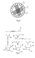
- damping is performed essentially by brushes 25.
- Each brush 25 is constituted by polyamide-based yarns one end of which is fixed near the junction of the lower vertical part of the inner wall of the cooling tower and of a receiving cone 26.
- the yarns make an angle about 45 ° with the trajectory of the balls in the cooling tower, that is to say substantially an angle of 45 ° with the vertical.
- four brushes 25 approximately 10 cm wide, opposed in pairs, are distributed along the periphery of the cooling tower, the free ends of the wires of two opposite brushes being superimposed.
- the diameter of the wires is smaller than the diameter of the balls. The flexibility of the brushes allows the balls to pass after damping, without altering their surface state.
- the damping of the balls by the brushes 25 before they pass through the receiving cone 26 can be completed by the use of rollers 27, preferably made of polyamide-based fabric, arranged on the lower periphery of the the inner wall of the cooling tower, above the brushes.
- the rollers 27, which can be arranged vertically ( figures 5 and 6 ) line the area immediately above the brushes. Any shock of a ball against the inner wall of the cooling tower, which may possibly be caused by a rebound of the ball on a brush 25, is thus also damped.
- the cone 26 of the cooling tower is extended by an airlock 28 provided with an inlet valve 29 and an outlet valve 30, both controlled by the control circuit 13.
- the airlock allows the extraction periodically the balls accumulated in the receiving cone 26. These then pass into a calibration system.
- the extracted beads fall by gravity on an upper screen 31 which retains the balls whose dimensions are greater than predetermined standards.
- the balls which have passed through the upper sieve 31 fall through a first funnel 32 onto a lower sieve 33, which allows the fine top balls to pass. These fall, through a second funnel 34, into a first tank 35.
- the balls corresponding to standards are retained in the lower screen 33.
- the balls are dropped too large and the balls corresponding to the standards, respectively through the third and fourth funnels 36 and 37, respectively in second and third bins 38 and 39.
- the balls are sorted into three categories, depending on their dimensions: the balls conform in the third tray 39 , the balls are too fine in the first tray 35 and the balls too large in the second tray 38.
- the control circuit 13 determines, from this weighing information, the percentage of beads extracted which are in the standards and intervenes on the granulation parameters to maintain a yield close to 100%.
- the control circuit 13 regulates and adjusts in particular the frequency of the vibrator 9.
- the increase in the frequency of the vibrator 9 tends to reduce the dimensions of the balls. For example, for a nominal frequency of the vibrator of 500Hz, the variation can relate to ⁇ 5Hz.
- the invention also relates to a device for producing spherical balls with a spherical ball selection device for sorting balls of uniform diameter, so as to separate all the balls that are not perfectly spherical.
- This type of sorting is adapted to the sorting of balls having already, before the sorting operation, all the same diameter, with close tolerances, but whose sphericity varies, in a relatively narrow range.
- the purpose of sorting is then to eliminate all the balls which are not perfectly spherical and which do not have a perfect surface state.
- the device comprises a tray, in the form of a hopper 43, in which are placed the balls to be sorted.
- a tray is disposed at the outlet of the device for producing spherical balls described above.
- the balls are brought on a succession of inclined planes 44a, 44b, 44c and 44d.
- Each inclined plane is located slightly below the previous inclined plane and a horizontal space e1 separates two successive inclined planes.
- the empty spaces between the inclined planes make it possible to eliminate the balls that reach the end of an inclined plane without having acquired a sufficient speed to pass on the next inclined plane without falling between the two successive inclined planes.
- the inclined planes do not all have the same surface condition and it is perfectly controlled for each diameter of balls to be sorted. Indeed, the speed of the balls depends on the combined effects of several types of forces, in particular gravity, friction forces, aerodynamic forces, interaction with the rolling surfaces, etc.
- the inclined planes are, preferably, constituted by sheets whose surface has a controlled roughness, greater for at least one of the first inclined planes, in the direction of movement of the balls.
- the roughness of the first inclined plane 44a is greater than that of the following inclined planes, so as to slow down more significantly the balls having surface defects.
- the trajectory of such a ball on a surface also having well-defined defects is indeed more complex, which tends to slow down the ball, causing its fall between the inclined planes 44a and 44b for example.
- the surface of the inclined planes is treated by any appropriate means, for example by sandblasting, microbilling or by any other mechanical and / or chemical means, or covered with a suitable coating, etc.
- the first two inclined planes 44a and 44b have a high roughness, which may be lower for the second.
- the last inclined plane 44d possibly the last two inclined planes 44c and 44d, can have a perfectly smooth surface. The interaction between the surface defects of the balls and the surface condition of the inclined planes thus makes it possible to rapidly eliminate the defective balls.
- each inclined plane and the spaces separating two successive inclined planes are determined, as a function of the diameter of the balls, so that the balls of very good sphericity roll on the inclined planes with a speed sufficient to pass from one plane inclined to the next .
- Each inclined plane comprises, at its upstream part, a curvature, upwards, intended to mitigate shocks upon receiving the balls on the inclined plane and to prevent any bouncing of the balls.
- each inclined plane has, in projection on the horizontal, a length L, which may be of the order of 10 to 15cm, and one width that can be of the order of 1m.
- the vertical space e2 separating two successive inclined planes may be less than or equal to 1cm, while the horizontal space e1 may be of the order of 1cm to 3cm.
- the number of inclined planes is inversely proportional to the size of the balls, preferably between 2 and 5. Furthermore, the more the balls are heavy, the faster they roll. Consequently, the inclination of the inclined planes must be low to allow a good selection.
- the balls leaving the hopper 43 are brought on the first inclined plane 44a via a rolling plane 45, slightly inclined, extending the bottom of the hopper 43.
- the balls come out at the base of the hopper 43 by a narrow passage 46, under the action of gravity forces, so as to form a single layer of rolling balls on the running surface.
- the stop 47 is constituted by a cylinder disposed at least over the entire width of the rolling surface 45, perpendicularly to the direction of flow of the balls on the rolling plane 45. The balls thus align with the stop 47.
- a space less than the diameter of a ball, separates the free end of the rolling plane 45 from the stop 47.
- the balls aligned in front of the stop 47 are ejected by saccades of the running surface.
- the ejection is preferably carried out by a ramp 48 consisting of a hollow tube in which a stream of compressed dry air or inert gas (nitrogen, argon, etc.) flows continuously.
- the ramp 48 is disposed parallel to the abutment 47, below the free end of the rolling surface 45. It comprises a plurality of air nozzles 49, directed towards the space between the free end of the plane of rotation. rolling and thrust, spread evenly along of the ramp 48 and constituting ejectors for lifting, preferably by jerks, the row of balls aligned in front of the stop 47.
- the ramp 48 is driven, by a cylinder (not shown), a reciprocating lateral movement, perpendicular to the direction of flow of the balls (from left to right on the figures 10 , 12 and 13 ) on the running surface 45.
- the respective positions of the ramp 48 and the running surface 45 for two extreme positions of the ramp during its back-and-forth movement are shown in FIGS. Figures 12 and 13 .
- the rolling plane 45 comprises, at least at its free end, obstacles 50, of uniform thickness ( figure 11 ), triangular in top view, which divide it into a plurality of corridors 51 of decreasing width.
- the obstacles 50 are very slightly protruding at the free end of the running surface.
- the base of the triangular section of an obstacle 50 parallel to the free end of the running surface 45, has a length I1, and the vertices of two adjacent obstacles are separated by a distance I2 ( figure 12 ).
- the basic angles of the triangular obstacles 50 constitute the limits of the displacement of the air nozzles 49 in the two extreme positions of the ramp 48 ( Figures 12 and 13 ).
- a stopping time of the ramp at both ends makes it possible to obtain an intermittent ejection, by saccades, thus making it possible to completely release the place, downstream, before the ejection of a new row of balls and limiting the interactions between them. beads that may alter their surface state. The quantity of balls present on each rolling zone is thus regulated and limited.
- 8 obstacles delimit 7 lanes 51.
- the length I1 of the triangular base of the obstacles 50 may be of the order of 20 to 30mm, for a distance I2 of the order of 130mm.
- the duration of movement of the ramp between its two extreme positions may, for example, be between 1s and a few seconds (frequency between 0.1 and 1Hz).
- the ejected balls are directed by a deflector 52 on an inclined face of a conveyor belt 53.
- the deflector 52 preferably curved, defines with the stop 47 a passage for the ejected balls, which then fall on an inclined face of the treadmill 53, disposed below the assembly consisting of the rolling surface 45, the stop 47, the ramp 48 and the deflector 52.
- the face of the conveyor belt on which the ejected balls fall is inclined in the same direction as the inclined planes 44a to 44d.
- the direction of rotation of the conveyor belt 53 is opposite to the direction of rotation of the balls on this face of the conveyor belt ( figure 8 ).
- the speed of movement of the treadmill is chosen so that the spherical balls rolling on its inclined face in the opposite direction of its displacement reach the first inclined plane.
- the speed of the treadmill can be of the order of 0.5 to 5m / min, preferably 2m / min.
- the treadmill makes a first selection. Indeed, balls with large surface defects or double balls, which can not roll or roll too slowly on the inclined face of the treadmill, are discharged to the rear by the treadmill and fall into a first tray 54 , while the balls having a good sphericity roll, in opposite directions, on the first inclined plane.
- the selected balls fall into a hopper 55.
- a movable slide 56 can be placed between the last inclined plane 44d and the hopper 55, so as to make a final selection between the balls before their reception in the hopper.
- the strip 56 has an upper edge connecting two walls, one of which directs the fastest balls to the hopper 56, while the other discharges the slower balls, which fall upstream of the upper edge.
- the selection device described above makes it possible to select spherical balls of uniform diameter as a function of their surface state. Only the balls having a perfect surface state reach the hopper 55. However, it can happen that glued balls reach the hopper 55. In practice, on about one million balls, 2 or 3 pairs of glued balls reach 'to the hopper. This is particularly the case when a pair 60 of glued balls falls on the conveyor belt 53, then on the various inclined planes, so that the rolling of the pair is not slowed down, for example when the axis S of longitudinal symmetry of the pair ( figure 15 ) is perfectly perpendicular to the direction of movement of the balls. To also eliminate the glued balls capable of reaching the hopper 55, the device is preferably completed by a toothed wheel 57 of large diameter, for example of the order of 30 cm, disposed downstream of the inclined planes.
- the funnel-shaped hopper 55 allows the balls to flow on the upper part of the toothed wheel 57.
- the latter is driven with a slow rotational movement about an inclined axis 58 and has grooves longitudinal dimensions 59 whose dimensions allow the rolling of an insulated ball and prevent the rolling of a pair 60 of glued balls ( Figures 14 and 15 ).
- the flawless balls roll in the grooves 59 of the toothed wheel and are collected in a second tank 61 disposed downstream of the toothed wheel.
- the pairs 60 of glued balls locked in the grooves rotate with the gear around the axis 58 and fall by gravity into a third container 62 when the gearwheel has made a U-turn and the groove in which the pair is located. 60 has reached the lower part of the gear wheel, above the third tray.
- the gear wheel 57 preferably comprises several hundred grooves.
- the bottom of the grooves 59 is about 1.2 to 1.5 times the diameter of the balls, so that a pair of bonded beads can not be placed perpendicularly to the groove and roll into it.
- the crown of the teeth of the toothed wheel is preferably pointed with a slight rounding.
- a deflector in the form of a circular arc matching the outer diameter of the toothed wheel can be placed perpendicularly to the grooves 59, so as to serve as a barrier in case of clogging at the outlet of the hopper 55.
- the invention is not limited to the particular embodiments shown.
- the number and arrangement of the orifices 8 may be different from those shown in the figures.
- the sorting and weighing of the balls at the outlet of the cooling tower can be carried out by any other suitable means capable of separating the balls corresponding to the standards of the other balls and to provide the information sought.
- the number and arrangement of sieves, funnels and bins may be different from what is shown.
- the control circuit 13 preferably receives signals representative of the various parameters that may have an influence on the balls produced by the device and controls the various members that can influence these parameters.
- the shape, the dimensions, the arrangement and the number of inclined planes of the selection device can be adapted to the dimensions of the balls to be selected.
- the stop 47 may not be cylindrical.
- the curved shapes are nevertheless advantageous, sharp edges may deteriorate the surface condition of the balls.
Landscapes
- Chemical & Material Sciences (AREA)
- Organic Chemistry (AREA)
- Chemical Kinetics & Catalysis (AREA)
- Manufacture Of Metal Powder And Suspensions Thereof (AREA)
- Combined Means For Separation Of Solids (AREA)
- Glanulating (AREA)
- Feeding, Discharge, Calcimining, Fusing, And Gas-Generation Devices (AREA)
- Electric Connection Of Electric Components To Printed Circuits (AREA)
- Joints Allowing Movement (AREA)
- Powder Metallurgy (AREA)
- Steroid Compounds (AREA)
- Friction Gearing (AREA)
- Nonmetallic Welding Materials (AREA)
Claims (19)
- Anlage zur Herstellung sphärischer Kugeln, die umfasst:- Mittel zum Einbringen von Material, aus dem die Kugeln entstehen sollen, in einen Schmelzbehälter (1),- einen zweiten Behälter (4), der mit dem Schmelzbehälter (1) so verbunden ist, dass er die Schmelze aufnehmen kann,- Mittel zur Bildung eines Strahls (14) aus der in dem zweiten Behälter enthaltenen Schmelze durch mindestens eine Öffnung (8),- Mittel zum Rütteln (9, 10, 11) zum Übertragen von Rüttelbewegungen auf die Öffnung (8), damit der Strahl (14) in Tröpfchen (15) umgewandelt wird,- einen Kühlturm (16), der am Ausgang der Öffnung (8) angeordnet und mit einem Inertgas gefüllt ist, in dem die Tröpfchen (15), die durch Schwerkraft herabfallen, aushärten und dann Kugeln bilden,- und Mittel zur Aufnahme der Kugeln an einem unteren Ende des Kühlturms (16),Anlage, die dadurch gekennzeichnet ist, dass sie eine Austrittskammer (20) in dem Schmelzbehälter (1) und Mittel (21, 22) zum Umrühren der in der Austrittskammer (20) enthaltenen Schmelze mit Ultraschall vor deren Übergang in den zweiten Behälter (4) umfasst, wobei das in dem Kühlturm (16) enthaltene Inertgas einen vorbestimmten Anteil an Sauerstoff enthält.
- Anlage nach Anspruch 1, dadurch gekennzeichnet, dass der in dem Inertgas des Kühlturms (16) enthaltene Sauerstoffanteil etwa 15 bis 150 ppm beträgt.
- Anlage nach einem der Ansprüche 1 und 2, dadurch gekennzeichnet, dass das Volumen der Austrittskammer (20) etwa 20 % niedriger als das des Schmelzbehälters (1) ist.
- Anlage nach einem der Ansprüche 1 bis 3, dadurch gekennzeichnet, dass der Schmelzbehälter (1) eine Wand (23) umfasst, welche die Austrittskammer (20) begrenzt, welche Wand (23) in ihrem unteren Bereich mit einem Durchlass (24) versehen ist, um das Einlaufen der Schmelze in die Austrittskammer (20) zu ermöglichen.
- Anlage nach einem der Ansprüche 1 bis 3, dadurch gekennzeichnet, dass die Ultraschall-Rüttelmittel eine Stange (21) umfassen, die in die Schmelze der Austrittskammer eingetaucht und vertikal hin und her bewegt wird.
- Anlage nach einem der Ansprüche 1 bis 5, dadurch gekennzeichnet, dass die Öffnung (8) aus einem Material hergestellt ist, das mit der Schmelze nicht benetzbar ist.
- Anlage nach einem der Ansprüche 1 bis 6, dadurch gekennzeichnet, dass die Aufnahmevorrichtungen für die Kugeln Stoßdämpfungsmittel umfassen.
- Anlage nach Anspruch 7, dadurch gekennzeichnet, dass die Stoßdämpfungsmittel Bürsten (25) umfassen, die aus Borsten auf Polyamidbasis bestehen und einen Winkel von etwa 45° zur Bahn der Kugeln in dem Kühlturm (16) bilden.
- Anlage nach Anspruch 8, dadurch gekennzeichnet, dass die Stoßdämpfungsmittel Walzen (27) aus Gewebe umfassen, die am unteren Umfang der Innenwand des Kühlturms (16) über den Bürsten (25) angeordnet sind.
- Anlage nach einem der Ansprüche 1 bis 9, dadurch gekennzeichnet, dass sie am Austritt des Kühlturms (16) Mittel (28, 29, 30) zum periodischen Austragen der Kugeln sowie Kalibrierungsmittel umfasst, die Mittel (31, 33) zum Trennen der Kugeln je nach ihrer Größe in drei Kategorien aufweist.
- Anlage nach Anspruch 10, dadurch gekennzeichnet, dass sie Mittel (40, 41, 42) zum Wiegen aller bei jeder Entnahmesequenz erhaltenen Kugeln jeder Kategorie, Mittel (13) zur Bestimmung eines prozentualen Anteils in vorbestimmten Normen ausgehend von von den Wiegemitteln übertragenen Daten (M1, M2, M3) sowie Mittel zum Anpassen der Frequenz der Mittel zum Rütteln (9) in Abhängigkeit von diesem prozentualen Anteil umfasst.
- Anlage nach einem der Ansprüche 1 bis 11, dadurch gekennzeichnet, dass sie eine Selektionsvorrichtung umfasst, die Mittel zum Zuführen der Kugeln auf eine erste schiefe Ebene (44a) einer Folge schiefer Ebenen (44a, 44b, 44c, 44d) umfasst, die durch Zwischenräume (e1, e2) vorbestimmter Abmessungen getrennt sind, wobei mindestens die erste schiefe Ebene (44a) in Bewegungsrichtung der Kugeln eine Oberfläche hat, die rauer ist als die der folgenden schiefen Ebenen.
- Anlage nach Anspruch 12, dadurch gekennzeichnet, dass mindestens die letzte schiefe Ebene (44d) eine vollkommen glatte Oberfläche hat.
- Anlage nach einem der Ansprüche 12 und 13, dadurch gekennzeichnet, dass die Mittel zum Zuführen der Kugeln auf die erste schiefe Ebene eine Rollebene (45), Anschlagmittel (47), Auswurfmittel (48, 49) zum stoßweisen Auswerfen der an die Anschlagmittel anschlagenden Kugeln von der Rollebene umfassen.
- Anlage nach Anspruch 14, dadurch gekennzeichnet, dass die Auswurfmittel eine hohle Rampe (48) umfassen, die seitlich hin und her bewegt wird und mit mehreren Luftstrahldüsen (49) versehen ist, die gleichmäßig entlang der Rampe verteilt sind.
- Anlage nach einem der Ansprüche 12 bis 15, dadurch gekennzeichnet, dass die Mittel zum Zuführen der Kugeln auf die erste schiefe Ebene (44a) ein Förderband (53) umfassen, das eine Seite hat, die in gleicher Richtung geneigt ist wie die schiefen Ebenen und eine Drehrichtung hat, die entgegengesetzt zur Rollrichtung der Kugeln auf der genannten Seite ist.
- Anlage nach Anspruch 16, dadurch gekennzeichnet, dass die Mittel zum Zuführen der Kugeln auf die erste schiefe Ebene (44a) Ablenkmittel (52) zum Führen der ausgeworfenen Kugeln auf die geneigte Seite des Förderbands (53) umfassen.
- Anlage nach einem der Ansprüche 12 bis 17, dadurch gekennzeichnet, dass sie nach den schiefen Ebenen (44a, 44b, 44c, 44d) ein Zahnrad (57) umfasst, das eine Drehbewegung um eine schräg abfallende Achse (58) ausführt und mit Längsrillen (59) versehen ist, deren Abmessungen das Rollen einer einzelnen Kugel ermöglicht und das Rollen eines Paars (60) aneinander haftender Kugeln verhindert.
- Anlage nach Anspruch 18, dadurch gekennzeichnet, dass sie erste Aufnahmemittel (61) für die fehlerfreien Kugeln umfasst, die in den Rillen (59) des Zahnrads (57) rollen, wobei die Paare (60) aneinander haftender, in den Rillen (59) blockierter Kugeln während der Drehung des Zahnrads (57) durch Schwerkraft in zweite Aufnahmevorrichtungen (62) fallen.
Applications Claiming Priority (4)
| Application Number | Priority Date | Filing Date | Title |
|---|---|---|---|
| FR0110007 | 2001-07-26 | ||
| FR0110007A FR2827793B1 (fr) | 2001-07-26 | 2001-07-26 | Dispositif de production de billes spheriques |
| FR0110702A FR2828418B1 (fr) | 2001-08-10 | 2001-08-10 | Dispositif de selection de billes spheriques |
| FR0110702 | 2001-08-10 |
Publications (2)
| Publication Number | Publication Date |
|---|---|
| EP1279450A1 EP1279450A1 (de) | 2003-01-29 |
| EP1279450B1 true EP1279450B1 (de) | 2009-06-17 |
Family
ID=26213117
Family Applications (1)
| Application Number | Title | Priority Date | Filing Date |
|---|---|---|---|
| EP02354113A Expired - Lifetime EP1279450B1 (de) | 2001-07-26 | 2002-07-19 | Vorrichtung zur Herstellung von sphärischen Kugeln |
Country Status (11)
| Country | Link |
|---|---|
| US (1) | US6676890B2 (de) |
| EP (1) | EP1279450B1 (de) |
| JP (1) | JP4118626B2 (de) |
| KR (1) | KR100866294B1 (de) |
| CN (1) | CN1197674C (de) |
| AT (1) | ATE433815T1 (de) |
| CA (1) | CA2393862A1 (de) |
| DE (1) | DE60232622D1 (de) |
| MY (1) | MY127347A (de) |
| SG (1) | SG103876A1 (de) |
| TW (1) | TW577780B (de) |
Families Citing this family (27)
| Publication number | Priority date | Publication date | Assignee | Title |
|---|---|---|---|---|
| TW577780B (en) * | 2001-07-26 | 2004-03-01 | Ind Des Poudres Spheriques | Device for producing spherical balls |
| US7976608B2 (en) * | 2005-03-09 | 2011-07-12 | Senju Metal Industry Co., Ltd. | Method and apparatus for manufacturing low melting point metal fine particles |
| CN100395040C (zh) * | 2005-12-08 | 2008-06-18 | 安徽精通科技有限公司 | 微电子封装锡球抛射筛选方法 |
| WO2008044459A1 (en) * | 2006-10-11 | 2008-04-17 | Freund Corporation | Apparatus for manufacturing seamless capsule |
| JP5590501B2 (ja) * | 2009-06-30 | 2014-09-17 | 日立金属株式会社 | 金属微小球の製造方法 |
| EP2305740B1 (de) | 2009-09-30 | 2011-06-08 | Ems-Patent Ag | Verfahren zur Herstellung von Polymerpartikeln |
| CN101844229B (zh) * | 2010-03-24 | 2012-05-23 | 峨嵋半导体材料研究所 | 高纯锑粒的制备方法及生产设备 |
| KR101745017B1 (ko) | 2011-12-05 | 2017-06-09 | 현대자동차주식회사 | 초음파 고온 진동법을 이용한 열제어 소재용 마이크로 입자와, 이것의 제조 장치 및 방법 |
| US8486582B1 (en) * | 2012-09-24 | 2013-07-16 | Battelle Memorial Institute | Surface modification to prevent oxide scale spallation |
| CN105170022B (zh) * | 2014-06-16 | 2017-11-10 | 新特能源股份有限公司 | 造粒装置、制备四氯化硅催化氢化反应用催化剂的制备方法及四氯化硅催化氢化反应方法 |
| DE102014110720B4 (de) * | 2014-07-29 | 2025-12-31 | Illinois Tool Works Inc. | Lötmodul |
| EP3000524A1 (de) * | 2014-09-29 | 2016-03-30 | Casale SA | Vorrichtung und Verfahren zum Prillen einer Flüssigkeit, vorzugsweise Harnstoffschmelze |
| TWI580509B (zh) * | 2015-11-13 | 2017-05-01 | Spherical forming device | |
| CN105655260B (zh) * | 2016-03-17 | 2018-03-13 | 大连理工大学 | 一种微互连凸点制备方法及装置 |
| CN105826207B (zh) * | 2016-03-17 | 2018-05-04 | 大连理工大学 | 一种核壳结构凸点制备方法及装置 |
| WO2018035599A1 (en) | 2016-08-24 | 2018-03-01 | 5N Plus Inc. | Low melting point metal or alloy powders atomization manufacturing processes |
| CN107570711A (zh) * | 2017-07-11 | 2018-01-12 | 张家港创博金属科技有限公司 | 一种脉冲小孔喷射法连续高效制备均一球形微粒子的方法及装置 |
| CN107377983A (zh) * | 2017-08-04 | 2017-11-24 | 米亚索乐装备集成(福建)有限公司 | 一种制备合金金属粉末的雾化装置 |
| CN110054396B (zh) * | 2018-01-18 | 2021-10-15 | 宁波大学 | 一种2s2g硫系玻璃微球制作装置 |
| CN110090596B (zh) * | 2018-01-30 | 2022-06-21 | 徐州市禾协肥业有限公司 | 一种斜面冷却造粒的方法及其肥料颗粒 |
| JP2021514028A (ja) | 2018-02-15 | 2021-06-03 | 5エヌ プラス インコーポレイテッド | 高融点金属または合金粉末アトマイズ製造プロセス |
| CN110465238B (zh) * | 2019-08-27 | 2020-05-12 | 温州市阳安电子科技有限公司 | 一种硬质合金旋转喷雾制粒机 |
| CN111482615A (zh) * | 2020-05-19 | 2020-08-04 | 郑州机械研究所有限公司 | 底漏浇铸超声波辅助系统和底漏浇铸系统 |
| CN114057487A (zh) * | 2021-12-14 | 2022-02-18 | 中钢集团南京新材料研究院有限公司 | 一种等静压石墨制备装置及制备方法 |
| CN114367244A (zh) * | 2022-02-22 | 2022-04-19 | 阳泉加林科技有限公司 | 用于宝珠砂喷吹制成球的装置 |
| CN116921231B (zh) * | 2023-07-31 | 2024-01-23 | 苏州荣文西邻精密科技有限公司 | 一种分选设备 |
| CN119457097B (zh) * | 2025-01-07 | 2025-04-04 | 江西小山新材料科技有限公司 | 一种锡球生产装置 |
Family Cites Families (15)
| Publication number | Priority date | Publication date | Assignee | Title |
|---|---|---|---|---|
| US171502A (en) | 1875-12-28 | Improvement in seed-separators | ||
| DE2253353A1 (de) | 1972-10-31 | 1974-07-11 | Knapsack Ag | Sortiereinrichtung |
| FR2471827A1 (fr) * | 1979-12-21 | 1981-06-26 | Extramet Sa | Dispositif pour la production de granules metalliques uniformes |
| DE3538267A1 (de) | 1984-12-21 | 1986-06-26 | Rudolf Dipl.-Ing. 4048 Grevenbroich Koppatz | Verfahren und vorrichtung zur herstellung von metallgranalien |
| JPS61221310A (ja) * | 1985-03-26 | 1986-10-01 | Agency Of Ind Science & Technol | 金属或は合金等の微粉末製造方法とその装置 |
| FR2600000B1 (fr) | 1986-06-13 | 1989-04-14 | Extramet Sa | Procede et dispositif de granulation d'un metal fondu |
| US5229016A (en) * | 1991-08-08 | 1993-07-20 | Microfab Technologies, Inc. | Method and apparatus for dispensing spherical-shaped quantities of liquid solder |
| JPH11128845A (ja) | 1997-10-30 | 1999-05-18 | Daizen:Kk | 選別装置及び選別方法 |
| JP2000328111A (ja) * | 1999-05-14 | 2000-11-28 | Nippon Steel Corp | 微小金属球の製造方法および装置 |
| JP2000328112A (ja) | 1999-05-24 | 2000-11-28 | Sumitomo Metal Mining Co Ltd | はんだボールの製造方法とその製造装置 |
| US6312498B1 (en) * | 1999-12-14 | 2001-11-06 | Mk Electron Co., Ltd. | Method of manufacturing solder balls |
| JP2001226706A (ja) * | 2000-02-15 | 2001-08-21 | Hitachi Metals Ltd | 微細金属球製造装置 |
| JP2001254108A (ja) * | 2000-03-14 | 2001-09-18 | Hitachi Metals Ltd | 微細金属球の製造方法並びに微細金属球製造装置 |
| US6491737B2 (en) * | 2000-05-22 | 2002-12-10 | The Regents Of The University Of California | High-speed fabrication of highly uniform ultra-small metallic microspheres |
| TW577780B (en) * | 2001-07-26 | 2004-03-01 | Ind Des Poudres Spheriques | Device for producing spherical balls |
-
2002
- 2002-07-10 TW TW091115330A patent/TW577780B/zh not_active IP Right Cessation
- 2002-07-12 SG SG200204286A patent/SG103876A1/en unknown
- 2002-07-15 US US10/194,011 patent/US6676890B2/en not_active Expired - Fee Related
- 2002-07-17 CA CA002393862A patent/CA2393862A1/en not_active Abandoned
- 2002-07-19 MY MYPI20022736A patent/MY127347A/en unknown
- 2002-07-19 AT AT02354113T patent/ATE433815T1/de not_active IP Right Cessation
- 2002-07-19 DE DE60232622T patent/DE60232622D1/de not_active Expired - Lifetime
- 2002-07-19 EP EP02354113A patent/EP1279450B1/de not_active Expired - Lifetime
- 2002-07-25 JP JP2002217045A patent/JP4118626B2/ja not_active Expired - Fee Related
- 2002-07-25 KR KR1020020043924A patent/KR100866294B1/ko not_active Expired - Fee Related
- 2002-07-26 CN CNB021270422A patent/CN1197674C/zh not_active Expired - Fee Related
Also Published As
| Publication number | Publication date |
|---|---|
| JP4118626B2 (ja) | 2008-07-16 |
| CN1197674C (zh) | 2005-04-20 |
| DE60232622D1 (de) | 2009-07-30 |
| MY127347A (en) | 2006-11-30 |
| ATE433815T1 (de) | 2009-07-15 |
| JP2003155505A (ja) | 2003-05-30 |
| TW577780B (en) | 2004-03-01 |
| KR20030010532A (ko) | 2003-02-05 |
| CA2393862A1 (en) | 2003-01-26 |
| US6676890B2 (en) | 2004-01-13 |
| CN1400073A (zh) | 2003-03-05 |
| SG103876A1 (en) | 2004-05-26 |
| US20030020213A1 (en) | 2003-01-30 |
| KR100866294B1 (ko) | 2008-10-31 |
| EP1279450A1 (de) | 2003-01-29 |
Similar Documents
| Publication | Publication Date | Title |
|---|---|---|
| EP1279450A1 (de) | Vorrichtung zur Herstellung von sphärischen Kugeln | |
| WO1981001811A1 (fr) | Procede de fabrication de granules metalliques, produits obtenus et dispositif pour la mise en oeuvre de ce procede | |
| FR2470635A1 (fr) | Procede et appareil pour le traitement, notamment l'enrobage ou l'agrandissement, de particules ou granules | |
| FR2470634A1 (fr) | Procede et appareil pour produire des granules de dimensions relativement grandes par croissance a partir de gouttelettes solidifiees | |
| FR2481947A1 (fr) | Granulateur a couche fluidisee par injection comportant une ouverture d'injection de gaz et une ouverture d'injection de liquide | |
| EP3996920B1 (de) | Vorrichtung und verfahren zur abscheidung eines körnigen materials in der generativen fertigung | |
| FR2872497A1 (fr) | Dispositif et procede pour le chargement d'une enceinte avec un solide divise comprenant un arbre de rotation creux | |
| US5791493A (en) | Polysilicon particle classifying apparatus | |
| FR3003778A1 (fr) | Procede et dispositif de tri de billes | |
| FR2695008A1 (fr) | Procédé et machine pour la fabrication de cigarettes. | |
| EP1584237B1 (de) | Verfahren zur Herstellung einer Waffeltüte vor dem Befüllen derselben, derart hergestellte Tüte und Anlage zur Durchführung des Verfahrens | |
| EP0216653B1 (de) | Granulierungsvorrichtung | |
| FR2541132A1 (fr) | Procede et appareil pour le melange de matieres particulaires | |
| FR2828418A1 (fr) | Dispositif de selection de billes spheriques | |
| FR2827793A1 (fr) | Dispositif de production de billes spheriques | |
| FR2683214A1 (fr) | Dispositif servant a distribuer des doses determinees d'un produit. | |
| FR2844212A1 (fr) | Procede et installation pour le tri morphologique automatique d'objets substantiellement spheriques. | |
| EP3224163A1 (de) | Vorrichtung und verfahren für gesteuerte förderung | |
| EP0086704B1 (de) | Verfahren und Vorrichtung zur Produktion von vollkommen sphärischen und porösen Körnern und so hergestellte Körner | |
| EP0168329B1 (de) | Becherwerk mit einer Vorrichtung zur Veränderung der Bechergeschwindigkeit in der Ladezone | |
| FR2869889A1 (fr) | Dispositif ejecteur pneumatique pour ligne de convoyage de produits tels que des fruits | |
| LU84792A1 (fr) | Appareil de granulation de matieres fondues | |
| FR3136999A3 (fr) | Dispositif de démêlage de petites pièces | |
| EP4606491A1 (de) | Vorrichtung zur abgabe eines materials | |
| FR3144763A1 (fr) | Dispositif pour tri de matériaux à l’aide de jets d’eau |
Legal Events
| Date | Code | Title | Description |
|---|---|---|---|
| PUAI | Public reference made under article 153(3) epc to a published international application that has entered the european phase |
Free format text: ORIGINAL CODE: 0009012 |
|
| AK | Designated contracting states |
Designated state(s): AT BE BG CH CY CZ DE DK EE ES FI FR GB GR IE IT LI LU MC NL PT SE SK TR |
|
| AX | Request for extension of the european patent |
Extension state: AL LT LV MK RO SI |
|
| 17P | Request for examination filed |
Effective date: 20030409 |
|
| AKX | Designation fees paid |
Designated state(s): AT BE BG CH CY CZ DE DK EE ES FI FR GB GR IE IT LI LU MC NL PT SE SK TR |
|
| GRAP | Despatch of communication of intention to grant a patent |
Free format text: ORIGINAL CODE: EPIDOSNIGR1 |
|
| GRAS | Grant fee paid |
Free format text: ORIGINAL CODE: EPIDOSNIGR3 |
|
| GRAA | (expected) grant |
Free format text: ORIGINAL CODE: 0009210 |
|
| RBV | Designated contracting states (corrected) |
Designated state(s): AT BE BG CH CY CZ DE DK EE ES FI GB GR IE IT LI LU MC NL PT SE SK TR |
|
| AK | Designated contracting states |
Kind code of ref document: B1 Designated state(s): AT BE BG CH CY CZ DE DK EE ES FI GB GR IE IT LI LU MC NL PT SE SK TR |
|
| REG | Reference to a national code |
Ref country code: GB Ref legal event code: FG4D Free format text: NOT ENGLISH |
|
| REG | Reference to a national code |
Ref country code: CH Ref legal event code: EP |
|
| REG | Reference to a national code |
Ref country code: IE Ref legal event code: FG4D Free format text: LANGUAGE OF EP DOCUMENT: FRENCH |
|
| REF | Corresponds to: |
Ref document number: 60232622 Country of ref document: DE Date of ref document: 20090730 Kind code of ref document: P |
|
| PG25 | Lapsed in a contracting state [announced via postgrant information from national office to epo] |
Ref country code: AT Free format text: LAPSE BECAUSE OF FAILURE TO SUBMIT A TRANSLATION OF THE DESCRIPTION OR TO PAY THE FEE WITHIN THE PRESCRIBED TIME-LIMIT Effective date: 20090617 Ref country code: FI Free format text: LAPSE BECAUSE OF FAILURE TO SUBMIT A TRANSLATION OF THE DESCRIPTION OR TO PAY THE FEE WITHIN THE PRESCRIBED TIME-LIMIT Effective date: 20090617 |
|
| PG25 | Lapsed in a contracting state [announced via postgrant information from national office to epo] |
Ref country code: SE Free format text: LAPSE BECAUSE OF FAILURE TO SUBMIT A TRANSLATION OF THE DESCRIPTION OR TO PAY THE FEE WITHIN THE PRESCRIBED TIME-LIMIT Effective date: 20090917 |
|
| NLV1 | Nl: lapsed or annulled due to failure to fulfill the requirements of art. 29p and 29m of the patents act | ||
| REG | Reference to a national code |
Ref country code: IE Ref legal event code: FD4D |
|
| PG25 | Lapsed in a contracting state [announced via postgrant information from national office to epo] |
Ref country code: IE Free format text: LAPSE BECAUSE OF FAILURE TO SUBMIT A TRANSLATION OF THE DESCRIPTION OR TO PAY THE FEE WITHIN THE PRESCRIBED TIME-LIMIT Effective date: 20090617 Ref country code: CZ Free format text: LAPSE BECAUSE OF FAILURE TO SUBMIT A TRANSLATION OF THE DESCRIPTION OR TO PAY THE FEE WITHIN THE PRESCRIBED TIME-LIMIT Effective date: 20090617 Ref country code: EE Free format text: LAPSE BECAUSE OF FAILURE TO SUBMIT A TRANSLATION OF THE DESCRIPTION OR TO PAY THE FEE WITHIN THE PRESCRIBED TIME-LIMIT Effective date: 20090617 Ref country code: ES Free format text: LAPSE BECAUSE OF FAILURE TO SUBMIT A TRANSLATION OF THE DESCRIPTION OR TO PAY THE FEE WITHIN THE PRESCRIBED TIME-LIMIT Effective date: 20090928 |
|
| BERE | Be: lapsed |
Owner name: I.P.S. INDUSTRIE DES POUDRES SPHERIQUES S.A. Effective date: 20090731 |
|
| PG25 | Lapsed in a contracting state [announced via postgrant information from national office to epo] |
Ref country code: NL Free format text: LAPSE BECAUSE OF FAILURE TO SUBMIT A TRANSLATION OF THE DESCRIPTION OR TO PAY THE FEE WITHIN THE PRESCRIBED TIME-LIMIT Effective date: 20090617 Ref country code: MC Free format text: LAPSE BECAUSE OF NON-PAYMENT OF DUE FEES Effective date: 20090731 Ref country code: SK Free format text: LAPSE BECAUSE OF FAILURE TO SUBMIT A TRANSLATION OF THE DESCRIPTION OR TO PAY THE FEE WITHIN THE PRESCRIBED TIME-LIMIT Effective date: 20090617 |
|
| REG | Reference to a national code |
Ref country code: CH Ref legal event code: PL |
|
| PG25 | Lapsed in a contracting state [announced via postgrant information from national office to epo] |
Ref country code: BG Free format text: LAPSE BECAUSE OF FAILURE TO SUBMIT A TRANSLATION OF THE DESCRIPTION OR TO PAY THE FEE WITHIN THE PRESCRIBED TIME-LIMIT Effective date: 20090917 Ref country code: PT Free format text: LAPSE BECAUSE OF FAILURE TO SUBMIT A TRANSLATION OF THE DESCRIPTION OR TO PAY THE FEE WITHIN THE PRESCRIBED TIME-LIMIT Effective date: 20091017 |
|
| PLBE | No opposition filed within time limit |
Free format text: ORIGINAL CODE: 0009261 |
|
| STAA | Information on the status of an ep patent application or granted ep patent |
Free format text: STATUS: NO OPPOSITION FILED WITHIN TIME LIMIT |
|
| PG25 | Lapsed in a contracting state [announced via postgrant information from national office to epo] |
Ref country code: DK Free format text: LAPSE BECAUSE OF FAILURE TO SUBMIT A TRANSLATION OF THE DESCRIPTION OR TO PAY THE FEE WITHIN THE PRESCRIBED TIME-LIMIT Effective date: 20090617 Ref country code: CH Free format text: LAPSE BECAUSE OF NON-PAYMENT OF DUE FEES Effective date: 20090731 Ref country code: LI Free format text: LAPSE BECAUSE OF NON-PAYMENT OF DUE FEES Effective date: 20090731 |
|
| 26N | No opposition filed |
Effective date: 20100318 |
|
| PG25 | Lapsed in a contracting state [announced via postgrant information from national office to epo] |
Ref country code: BE Free format text: LAPSE BECAUSE OF NON-PAYMENT OF DUE FEES Effective date: 20090731 |
|
| PG25 | Lapsed in a contracting state [announced via postgrant information from national office to epo] |
Ref country code: GR Free format text: LAPSE BECAUSE OF FAILURE TO SUBMIT A TRANSLATION OF THE DESCRIPTION OR TO PAY THE FEE WITHIN THE PRESCRIBED TIME-LIMIT Effective date: 20090918 |
|
| PGFP | Annual fee paid to national office [announced via postgrant information from national office to epo] |
Ref country code: DE Payment date: 20100714 Year of fee payment: 9 |
|
| PGFP | Annual fee paid to national office [announced via postgrant information from national office to epo] |
Ref country code: GB Payment date: 20100714 Year of fee payment: 9 |
|
| PG25 | Lapsed in a contracting state [announced via postgrant information from national office to epo] |
Ref country code: IT Free format text: LAPSE BECAUSE OF FAILURE TO SUBMIT A TRANSLATION OF THE DESCRIPTION OR TO PAY THE FEE WITHIN THE PRESCRIBED TIME-LIMIT Effective date: 20090617 |
|
| PG25 | Lapsed in a contracting state [announced via postgrant information from national office to epo] |
Ref country code: LU Free format text: LAPSE BECAUSE OF NON-PAYMENT OF DUE FEES Effective date: 20090719 |
|
| PG25 | Lapsed in a contracting state [announced via postgrant information from national office to epo] |
Ref country code: TR Free format text: LAPSE BECAUSE OF FAILURE TO SUBMIT A TRANSLATION OF THE DESCRIPTION OR TO PAY THE FEE WITHIN THE PRESCRIBED TIME-LIMIT Effective date: 20090617 |
|
| PG25 | Lapsed in a contracting state [announced via postgrant information from national office to epo] |
Ref country code: CY Free format text: LAPSE BECAUSE OF FAILURE TO SUBMIT A TRANSLATION OF THE DESCRIPTION OR TO PAY THE FEE WITHIN THE PRESCRIBED TIME-LIMIT Effective date: 20090617 |
|
| GBPC | Gb: european patent ceased through non-payment of renewal fee |
Effective date: 20110719 |
|
| PG25 | Lapsed in a contracting state [announced via postgrant information from national office to epo] |
Ref country code: DE Free format text: LAPSE BECAUSE OF NON-PAYMENT OF DUE FEES Effective date: 20120201 |
|
| REG | Reference to a national code |
Ref country code: DE Ref legal event code: R119 Ref document number: 60232622 Country of ref document: DE Effective date: 20120201 |
|
| PG25 | Lapsed in a contracting state [announced via postgrant information from national office to epo] |
Ref country code: GB Free format text: LAPSE BECAUSE OF NON-PAYMENT OF DUE FEES Effective date: 20110719 |