EP1279458A2 - Drehendes Reibungschweissverfahren und mit diesem Verfahren hergestelltes Element - Google Patents
Drehendes Reibungschweissverfahren und mit diesem Verfahren hergestelltes Element Download PDFInfo
- Publication number
- EP1279458A2 EP1279458A2 EP02016344A EP02016344A EP1279458A2 EP 1279458 A2 EP1279458 A2 EP 1279458A2 EP 02016344 A EP02016344 A EP 02016344A EP 02016344 A EP02016344 A EP 02016344A EP 1279458 A2 EP1279458 A2 EP 1279458A2
- Authority
- EP
- European Patent Office
- Prior art keywords
- members
- rotary tool
- pin portion
- friction stir
- welded
- Prior art date
- Legal status (The legal status is an assumption and is not a legal conclusion. Google has not performed a legal analysis and makes no representation as to the accuracy of the status listed.)
- Withdrawn
Links
Images




Classifications
-
- B—PERFORMING OPERATIONS; TRANSPORTING
- B23—MACHINE TOOLS; METAL-WORKING NOT OTHERWISE PROVIDED FOR
- B23K—SOLDERING OR UNSOLDERING; WELDING; CLADDING OR PLATING BY SOLDERING OR WELDING; CUTTING BY APPLYING HEAT LOCALLY, e.g. FLAME CUTTING; WORKING BY LASER BEAM
- B23K33/00—Specially-profiled edge portions of workpieces for making soldering or welding connections; Filling the seams formed thereby
-
- B—PERFORMING OPERATIONS; TRANSPORTING
- B23—MACHINE TOOLS; METAL-WORKING NOT OTHERWISE PROVIDED FOR
- B23K—SOLDERING OR UNSOLDERING; WELDING; CLADDING OR PLATING BY SOLDERING OR WELDING; CUTTING BY APPLYING HEAT LOCALLY, e.g. FLAME CUTTING; WORKING BY LASER BEAM
- B23K20/00—Non-electric welding by applying impact or other pressure, with or without the application of heat, e.g. cladding or plating
- B23K20/12—Non-electric welding by applying impact or other pressure, with or without the application of heat, e.g. cladding or plating the heat being generated by friction; Friction welding
- B23K20/122—Non-electric welding by applying impact or other pressure, with or without the application of heat, e.g. cladding or plating the heat being generated by friction; Friction welding using a non-consumable tool, e.g. friction stir welding
-
- B—PERFORMING OPERATIONS; TRANSPORTING
- B23—MACHINE TOOLS; METAL-WORKING NOT OTHERWISE PROVIDED FOR
- B23K—SOLDERING OR UNSOLDERING; WELDING; CLADDING OR PLATING BY SOLDERING OR WELDING; CUTTING BY APPLYING HEAT LOCALLY, e.g. FLAME CUTTING; WORKING BY LASER BEAM
- B23K20/00—Non-electric welding by applying impact or other pressure, with or without the application of heat, e.g. cladding or plating
- B23K20/12—Non-electric welding by applying impact or other pressure, with or without the application of heat, e.g. cladding or plating the heat being generated by friction; Friction welding
- B23K20/122—Non-electric welding by applying impact or other pressure, with or without the application of heat, e.g. cladding or plating the heat being generated by friction; Friction welding using a non-consumable tool, e.g. friction stir welding
- B23K20/127—Friction stir welding involving a mechanical connection
-
- B—PERFORMING OPERATIONS; TRANSPORTING
- B23—MACHINE TOOLS; METAL-WORKING NOT OTHERWISE PROVIDED FOR
- B23K—SOLDERING OR UNSOLDERING; WELDING; CLADDING OR PLATING BY SOLDERING OR WELDING; CUTTING BY APPLYING HEAT LOCALLY, e.g. FLAME CUTTING; WORKING BY LASER BEAM
- B23K20/00—Non-electric welding by applying impact or other pressure, with or without the application of heat, e.g. cladding or plating
- B23K20/12—Non-electric welding by applying impact or other pressure, with or without the application of heat, e.g. cladding or plating the heat being generated by friction; Friction welding
- B23K20/122—Non-electric welding by applying impact or other pressure, with or without the application of heat, e.g. cladding or plating the heat being generated by friction; Friction welding using a non-consumable tool, e.g. friction stir welding
- B23K20/128—Non-electric welding by applying impact or other pressure, with or without the application of heat, e.g. cladding or plating the heat being generated by friction; Friction welding using a non-consumable tool, e.g. friction stir welding making use of additional material
-
- B—PERFORMING OPERATIONS; TRANSPORTING
- B23—MACHINE TOOLS; METAL-WORKING NOT OTHERWISE PROVIDED FOR
- B23K—SOLDERING OR UNSOLDERING; WELDING; CLADDING OR PLATING BY SOLDERING OR WELDING; CUTTING BY APPLYING HEAT LOCALLY, e.g. FLAME CUTTING; WORKING BY LASER BEAM
- B23K20/00—Non-electric welding by applying impact or other pressure, with or without the application of heat, e.g. cladding or plating
- B23K20/16—Non-electric welding by applying impact or other pressure, with or without the application of heat, e.g. cladding or plating with interposition of special material to facilitate connection of the parts, e.g. material for absorbing or producing gas
-
- B—PERFORMING OPERATIONS; TRANSPORTING
- B23—MACHINE TOOLS; METAL-WORKING NOT OTHERWISE PROVIDED FOR
- B23K—SOLDERING OR UNSOLDERING; WELDING; CLADDING OR PLATING BY SOLDERING OR WELDING; CUTTING BY APPLYING HEAT LOCALLY, e.g. FLAME CUTTING; WORKING BY LASER BEAM
- B23K20/00—Non-electric welding by applying impact or other pressure, with or without the application of heat, e.g. cladding or plating
- B23K20/22—Non-electric welding by applying impact or other pressure, with or without the application of heat, e.g. cladding or plating taking account of the properties of the materials to be welded
- B23K20/227—Non-electric welding by applying impact or other pressure, with or without the application of heat, e.g. cladding or plating taking account of the properties of the materials to be welded with ferrous layer
- B23K20/2275—Non-electric welding by applying impact or other pressure, with or without the application of heat, e.g. cladding or plating taking account of the properties of the materials to be welded with ferrous layer the other layer being aluminium
-
- B—PERFORMING OPERATIONS; TRANSPORTING
- B23—MACHINE TOOLS; METAL-WORKING NOT OTHERWISE PROVIDED FOR
- B23K—SOLDERING OR UNSOLDERING; WELDING; CLADDING OR PLATING BY SOLDERING OR WELDING; CUTTING BY APPLYING HEAT LOCALLY, e.g. FLAME CUTTING; WORKING BY LASER BEAM
- B23K20/00—Non-electric welding by applying impact or other pressure, with or without the application of heat, e.g. cladding or plating
- B23K20/22—Non-electric welding by applying impact or other pressure, with or without the application of heat, e.g. cladding or plating taking account of the properties of the materials to be welded
- B23K20/233—Non-electric welding by applying impact or other pressure, with or without the application of heat, e.g. cladding or plating taking account of the properties of the materials to be welded without ferrous layer
- B23K20/2333—Non-electric welding by applying impact or other pressure, with or without the application of heat, e.g. cladding or plating taking account of the properties of the materials to be welded without ferrous layer one layer being aluminium, magnesium or beryllium
-
- B—PERFORMING OPERATIONS; TRANSPORTING
- B23—MACHINE TOOLS; METAL-WORKING NOT OTHERWISE PROVIDED FOR
- B23K—SOLDERING OR UNSOLDERING; WELDING; CLADDING OR PLATING BY SOLDERING OR WELDING; CUTTING BY APPLYING HEAT LOCALLY, e.g. FLAME CUTTING; WORKING BY LASER BEAM
- B23K35/00—Rods, electrodes, materials, or media, for use in soldering, welding, or cutting
- B23K35/001—Interlayers, transition pieces for metallurgical bonding of workpieces
- B23K35/004—Interlayers, transition pieces for metallurgical bonding of workpieces at least one of the workpieces being of a metal of the iron group
-
- H—ELECTRICITY
- H10—SEMICONDUCTOR DEVICES; ELECTRIC SOLID-STATE DEVICES NOT OTHERWISE PROVIDED FOR
- H10W—GENERIC PACKAGES, INTERCONNECTIONS, CONNECTORS OR OTHER CONSTRUCTIONAL DETAILS OF DEVICES COVERED BY CLASS H10
- H10W40/00—Arrangements for thermal protection or thermal control
- H10W40/01—Manufacture or treatment
- H10W40/03—Manufacture or treatment of arrangements for cooling
- H10W40/037—Assembling together parts thereof
-
- B—PERFORMING OPERATIONS; TRANSPORTING
- B23—MACHINE TOOLS; METAL-WORKING NOT OTHERWISE PROVIDED FOR
- B23K—SOLDERING OR UNSOLDERING; WELDING; CLADDING OR PLATING BY SOLDERING OR WELDING; CUTTING BY APPLYING HEAT LOCALLY, e.g. FLAME CUTTING; WORKING BY LASER BEAM
- B23K2103/00—Materials to be soldered, welded or cut
- B23K2103/08—Non-ferrous metals or alloys
- B23K2103/10—Aluminium or alloys thereof
-
- B—PERFORMING OPERATIONS; TRANSPORTING
- B23—MACHINE TOOLS; METAL-WORKING NOT OTHERWISE PROVIDED FOR
- B23K—SOLDERING OR UNSOLDERING; WELDING; CLADDING OR PLATING BY SOLDERING OR WELDING; CUTTING BY APPLYING HEAT LOCALLY, e.g. FLAME CUTTING; WORKING BY LASER BEAM
- B23K2103/00—Materials to be soldered, welded or cut
- B23K2103/18—Dissimilar materials
- B23K2103/20—Ferrous alloys and aluminium or alloys thereof
-
- B—PERFORMING OPERATIONS; TRANSPORTING
- B23—MACHINE TOOLS; METAL-WORKING NOT OTHERWISE PROVIDED FOR
- B23K—SOLDERING OR UNSOLDERING; WELDING; CLADDING OR PLATING BY SOLDERING OR WELDING; CUTTING BY APPLYING HEAT LOCALLY, e.g. FLAME CUTTING; WORKING BY LASER BEAM
- B23K2103/00—Materials to be soldered, welded or cut
- B23K2103/18—Dissimilar materials
- B23K2103/22—Ferrous alloys and copper or alloys thereof
-
- B—PERFORMING OPERATIONS; TRANSPORTING
- B23—MACHINE TOOLS; METAL-WORKING NOT OTHERWISE PROVIDED FOR
- B23K—SOLDERING OR UNSOLDERING; WELDING; CLADDING OR PLATING BY SOLDERING OR WELDING; CUTTING BY APPLYING HEAT LOCALLY, e.g. FLAME CUTTING; WORKING BY LASER BEAM
- B23K35/00—Rods, electrodes, materials, or media, for use in soldering, welding, or cutting
- B23K35/001—Interlayers, transition pieces for metallurgical bonding of workpieces
- B23K35/002—Interlayers, transition pieces for metallurgical bonding of workpieces at least one of the workpieces being of light metal
-
- B—PERFORMING OPERATIONS; TRANSPORTING
- B23—MACHINE TOOLS; METAL-WORKING NOT OTHERWISE PROVIDED FOR
- B23K—SOLDERING OR UNSOLDERING; WELDING; CLADDING OR PLATING BY SOLDERING OR WELDING; CUTTING BY APPLYING HEAT LOCALLY, e.g. FLAME CUTTING; WORKING BY LASER BEAM
- B23K35/00—Rods, electrodes, materials, or media, for use in soldering, welding, or cutting
- B23K35/001—Interlayers, transition pieces for metallurgical bonding of workpieces
- B23K35/007—Interlayers, transition pieces for metallurgical bonding of workpieces at least one of the workpieces being of copper or another noble metal
Definitions
- the present invention relates to a friction stir welding method for welding by use of a rotary tool having a pin portion and a shoulder portion.
- the present invention relates to a welded component part obtained by the friction stir welding method.
- the friction stir welding method is a method wherein a pin portion of a rotary tool made of a material harder than members to be welded is inserted between abutment surfaces of the members to be welded, and frictional heat and plastic flow are caused at the abutment surfaces by rotation and movement of the rotary tool, thereby welding the members.
- a pin portion of a rotary tool made of a material harder than members to be welded is inserted between abutment surfaces of the members to be welded, and frictional heat and plastic flow are caused at the abutment surfaces by rotation and movement of the rotary tool, thereby welding the members.
- One example of the friction stir welding method is described in Japanese Patent Laid-open No. 11-10368 (1999). Since the members to be welded can be welded at a temperature equal to the melting point or below thereof by the friction stir welding, this technique has the effects that strain after welding is little, the surfaces of the members remain aesthetically good, and so on.
- the friction stir welding method is suitable for welding members which are the same or similar in physical properties or mechanical properties.
- the members to be welded are conspicuously different in physical properties, for example, melting point or density, or where the members to be welded are conspicuously different in mechanical properties, the friction stir welding method results in that a defective weld is liable to be generated and a sound weld is difficult to obtain.
- the present invention resides in that friction stir welding is conducted such that members to be welded are abutted against each other, a pin portion of a rotary tool is inserted to one of the members, while the pin portion is not inserted to the other of the members but only a shoulder portion of the rotary tool is brought into contact with the other of the members.
- the present invention is not a conventional simple friction stir welding but is a novel friction stir welding.
- a coat layer of a metal capable of easily coupling with the opponent member on a metallic basis is provided on one or both of the abutment surfaces of the members to be welded.
- holes are provided in the welding surface of the member to be welded on the side where the pin portion of the rotary tool is not inserted.
- an upper surface of the member to be welded on the side where the pin portion of the rotary tool is not inserted is covered with the same material as that of the other member to be welded, and the shoulder portion of the rotary tool is brought into contact with the cover portion.
- the welding method according to the present invention is extremely suitable for welding copper or a copper alloy and aluminum or an aluminum alloy, copper or a copper alloy and titanium or a titanium alloy, iron or an iron alloy and aluminum or an aluminum alloy, and copper or a copper alloy and iron or an iron alloy.
- the welding method is suitable also for welding magnesium or a magnesium alloy and copper or a copper alloy, and magnesium or a magnesium alloy and iron or an iron alloy.
- Copper and aluminum has a solid solubility at room temperature of as extremely low as not more than 10%, and it is impossible or extremely difficult to weld copper and aluminum by an ordinary welding method. Even where copper and aluminum are subjected to friction stir welding by use of a rotary tool having a pin portion and a shoulder portion, it is difficult to obtain a sound weld. According to experiments conducted by the present inventors, friction stir welding of copper and aluminum resulted in that void was generated in the weld and a multiplicity of burrs were generated at the surface portion of the weld.
- the welding method according to the present invention can be applied also to the cases of welding a single crystal metal, a directionally solidified metal or a powder dispersion reinforced material to an ordinary metallic material. In this case, according to the present invention, it is possible to achieve welding without impairing the single crystal structure, the directionally solidified structure or the powder dispersion properties.
- the welding method according to the present invention can be applied also to the cases of welding a ceramic and a metallic material, and an organic material and a metallic material.
- Figs. 1 to 3 show one embodiment of the present invention. The case of welding aluminum and copper will be described as an example.
- a rotary tool 1 has a pin portion 2 and a shoulder portion 3.
- the friction stir welding is conducted by inserting the pin portion 2 of the rotary tool 1 to the members to be welded and moving the rotary tool 1.
- the pin portion 2 is inserted to the side of one of the members 4, 5 to be welded, and the pin portion 2 is not inserted to the side of the other of the members 4, 5 to be welded.
- the shoulder portion 3 of the rotary tool 1 is set in contact with the upper surface of the member to be welded on the side where the pin portion 2 is not inserted. It is desirable that the insertion position of the pin portion 2 is as close as possible to the abutment surfaces 6 of the members to be welded.
- the reaction layer is as thin as possible, for example, not more than 5 ⁇ m in thickness. Where the thickness of the reaction layer is as great as 50 ⁇ m or more, the weld is extremely low in mechanical strength, and breakage starting from the weld is liable to occur.
- the pin portion In order to reduce the thickness of the reaction layer formed at the welding interface, it is desirable to insert the pin portion on the side of the member which is lower in melting point. Where the pin portion is inserted on the side of the member higher in melting point, the plastic flow portion reaches a higher temperature, so that diffusion is liable to proceed more rapidly, it becomes difficult to control the thickness of the reaction layer, and the reaction layer is liable to be formed in a larger thickness, as compared with the case where the pin portion is inserted on the side of the member lower in melting point.
- the insertion of the pin portion on the side of the member lower in melting point also has the effects that the life of the rotary tool can be prolonged, and plastic flow can be caused at a lower temperature.
- the thickness of the reaction layer can be regulated also by controlling the rotational speed of the rotary tool.
- the welding method according to the present invention utilizes the plastic flow due to the friction stir action. Therefore, it is also desirable to insert the pin portion of the rotary tool on the side of the member which is more liable to undergo plastic flow.
- FIGs. 1 to 3 By the method shown in Figs. 1 to 3, an aluminum member 4 and a copper member 5 were welded.
- the pin portion 2 of the rotary tool 1 was inserted on the side of the aluminum member 4, and welding was conducted while rotating the tool 1 counterclockwise relative to the moving direction of the tool 1, namely, in the direction of arrow 7, with a tool rotational frequency of 1500 rpm and a tool movement velocity of 100 mm/min. As a result, a sound weld free of defects such as void was obtained.
- pairs of a single crystal material of nickel and stainless steel, a directional crystal material and stainless steel, and an alumina dispersion reinforced alloy and carbon steel were welded by the method shown in Fig. 1 by inserting the pin portion of the rotary tool on the side of stainless steel and on the side of carbon steel, respectively. In each of the cases, a sound weld free of defects was obtained.
- the rotary tool in many cases, has a pin portion which is threaded.
- the rotating direction of the rotary tool is important. For example, where the pin portion is threaded clockwise toward the tip end portion of the pin, it is desirable to rotate the rotary tool counterclockwise. Where the pin portion is threaded counterclockwise, it is naturally desirable to rotate the rotary tool clockwise.
- the plastic flow is caused to occur downwards, so that it is possible to prevent the flowing metal from flowing out to the surface of the weld portion to form burrs.
- the rotating direction of the tool is inverted, an upward plastic flow phenomenon occurs, so that the metal in plastic flow will flow out to the surface to form burrs on the surface of the weld, and void will be generated in the weld.
- the temperature profile in the vicinity of the weld portion in the case where the rotary tool is inserted to the members to be welded and the profile of frictional heat the temperature is highest in the vicinity of the center portion of the rotary tool, while on the other hand the frictional heat is lowest in the vicinity of the tip end of the pin of the rotary tool.
- the abutment surfaces of the members to be welded are inclined, as shown in Fig. 4, and the rotary tool is vertically inserted towards the members to be welded from above, it is possible to set the center portion of the tip end of the pin close to the abutment surfaces.
- the pin portion of the rotary tool is slantly inserted toward the abutment surfaces as shown in Fig. 5, whereby the center portion of the tip end of the pin can be set close to the abutment surfaces.
- a copper member 5 and a titanium member 9 were welded together at a rotational frequency of the rotary tool of 1500 rpm and a moving velocity of the tool of 50 mm/min, upon which a sound weld free of defects was obtained.
- Copper and titanium have a melting point difference of 400°C and a solid solubility at room temperature as low as not more than 1%.
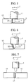
- Fig. 5 shows an embodiment of welding two members by providing the welding surface of one of the members with a coat layer of a metal capable of being easily coupled with the other of the members on a metallic basis.
- the coat layer of a metal may be provided on either one or both of the members to be welded. Where the coat layer of a metal is provided on one of the members, the coat. layer should be provided on the side where the pin portion of the rotary member is not inserted. In this case, as shown, the pin can be inserted up to the portion of the coat layer.
- the thickness of the reaction layer was as small as not more than 0.5 ⁇ m, and a weld having the same degree of tensile strength as the aluminum member was obtained.
- the weld was free of defects such as voids.
- Fig. 6 shows the case of providing a coat layer of a metal on the welding surface of one of the members to be welded, in the method shown in Fig. 4.
- a layer 12 of a solder material composed of silver and copper and having a melting point of 800°C was clad on the surface of an iron member 10 by pressure welding, and welding of the iron member 10 and a copper member 5 was conducted at a rotational frequency of the rotary tool of 2000 rpm and a moving velocity of the tool of 10 mm/min, upon which a sound weld free of defects was obtained.
- Fig. 7 shows an embodiment in which a coat layer of a metal is provided in a large thickness on the welding surface of one of the members to be welded, and frictional stir welding is conducted by inserting a pin portion of a rotary tool between the other of the members and the metal coat layer.
- a stainless steel member 13 and a copper alloy member 14 each being 5 mm in thickness, 100 mm in width and 200 mm in length were subjected to friction stir welding by providing a clad layer 15 of 10 mm in thickness of the same material as the copper alloy member 14 on the surface of the stainless steel member 13 and using a rotary tool having a pin portion diameter of 3 mm, a pin length of 4.5 mm and a shoulder portion diameter of 8 mm, upon which a sound weld free of defects was obtained.
- a copper alloy member and an aluminum member were 2 mm in thickness, 100 mm in width and 5 mm in length.
- a clad layer of 5 mm in thickness of the same material as the aluminum alloy member was provided on the copper alloy side by cold rolling.
- a rotary tool having a pin portion diameter of 2 mm, a pin length of 1.5 mm and a shoulder portion diameter of 5 mm and provided with a spiral thread clockwise toward the tip end of the pin was used. The pin portion of the rotary tool was inserted so as to be astride the aluminum member and the clad layer. As a result, a sound weld free of defects was obtained.
- a ceramic member consisting of aluminum nitride and an aluminum alloy were welded.
- a clad layer of 4 mm in thickness of the same material as the aluminum member was preliminarily formed on the ceramic member side. As a result, good welding could be achieved.
- stirring and mixing of both members may slightly occur in the vicinity of the upper surface with which the shoulder portion of the rotary tool makes contact.
- it is desirable that a plate of the same material as the member on the side where the pin is inserted is disposed on a portion with which the shoulder portion of the rotary tool makes contact.
- Figs. 8 and 9 show an example of welding of an aluminum member 4 and a copper member 5, in which part of an upper portion of the copper member 5 is slantly cut off, part of the aluminum member 4 is projected there to form a roof 4a, and the shoulder portion 3 of the rotary tool 1 is brought into contact only with the aluminum member.
- Figs. 10 and 11 show an example of welding in which a plate 16 of the same material as the aluminum member 4 is disposed at an upper portion of the abutment surfaces of the aluminum member 4 and the copper member 5, and welding is conducted under the condition where the shoulder portion 3 does not make contact with the copper member 5.
- stirring and mixing of both members in the vicinity of the upper portion with which the shoulder portion makes contact can be suppressed.
- the methods as shown in Figs. 8 to 11 were found effective for practical welding of copper and aluminum and of copper and titanium.
- Fig. 12 shows an example of welding two members to be welded in which the welding surface of one of the members is provided with a hole or holes.
- the hole or holes 17 are provided on the side where the pin of the rotary tool is not inserted.
- One or a plurality of the holes may be provided.
- the hole is desirably smaller at the entrance and larger in the inside.
- Fig. 13 shows an example of a semiconductor apparatus in which semiconductor devices 21 are mounted on a heat sink 30 manufactured by application of the welding technique according to the present invention.
- the heat sink 20 has a structure in which abutment surfaces 24 of aluminum 22 and copper 23 are welded by the friction stir welding according to the present invention, fins are provided on the side of aluminum 22, and semiconductor devices are mounted on copper 23.
- the semiconductor devices 21 and an insulating substrate 25 are soldered to each other, and the insulating substrate 25 and copper 23 are also soldered to each other.
Landscapes
- Engineering & Computer Science (AREA)
- Mechanical Engineering (AREA)
- Pressure Welding/Diffusion-Bonding (AREA)
Applications Claiming Priority (4)
| Application Number | Priority Date | Filing Date | Title |
|---|---|---|---|
| JP2001223768A JP2003039183A (ja) | 2001-07-25 | 2001-07-25 | 摩擦攪拌接合方法及び接合体 |
| JP2001223768 | 2001-07-25 | ||
| JP2002204976 | 2002-07-15 | ||
| JP2002204976A JP2004042117A (ja) | 2002-07-15 | 2002-07-15 | 摩擦攪拌接合方法とその方法によって接合された部品 |
Publications (2)
| Publication Number | Publication Date |
|---|---|
| EP1279458A2 true EP1279458A2 (de) | 2003-01-29 |
| EP1279458A3 EP1279458A3 (de) | 2004-07-28 |
Family
ID=26619203
Family Applications (1)
| Application Number | Title | Priority Date | Filing Date |
|---|---|---|---|
| EP02016344A Withdrawn EP1279458A3 (de) | 2001-07-25 | 2002-07-25 | Drehendes Reibungschweissverfahren und mit diesem Verfahren hergestelltes Element |
Country Status (2)
| Country | Link |
|---|---|
| US (2) | US7097091B2 (de) |
| EP (1) | EP1279458A3 (de) |
Cited By (16)
| Publication number | Priority date | Publication date | Assignee | Title |
|---|---|---|---|---|
| EP1400302A1 (de) * | 2002-09-20 | 2004-03-24 | Hitachi, Ltd. | Verfahren zum Verbinden von metallischen Werkstoffen mittels eines Reibrührwerkzeugs |
| EP1442820A1 (de) * | 2003-01-30 | 2004-08-04 | Gkss-Forschungszentrum Geesthacht Gmbh | Verfahren und Vorrichtung zum Verbinden von wenigstens zwei aneinanderliegenden Werkstücken nach der Methode des Reibrührschweissens |
| EP1563942A4 (de) * | 2002-11-13 | 2007-12-12 | Nippon Light Metal Co | Verbindungsverfahren für aluminiumpulverlegierung |
| CN101559530B (zh) * | 2007-12-21 | 2013-11-06 | 林德股份公司 | 用于连接管底和管的方法以及用于实施该方法的摩擦工具 |
| CN104332724A (zh) * | 2014-10-24 | 2015-02-04 | 江苏万奇电器集团有限公司 | 一种铜铝对接加叠接导电排 |
| WO2015036562A1 (de) * | 2013-09-12 | 2015-03-19 | Universität Stuttgart | VERFAHREN ZUM STUMPFVERSCHWEIßEN UND RÜHRREIBSCHWEIßWERKZEUG |
| CN105033475A (zh) * | 2015-09-18 | 2015-11-11 | 哈尔滨工业大学 | 用于铝钢材料对接的钢侧高频感应加热搅拌摩擦焊方法 |
| JP2016505789A (ja) * | 2013-01-11 | 2016-02-25 | ウー・シン・イーエムシー・カンパニー・リミテッド | 摩擦撹拌溶接を利用したハイブリッドドライブシャフト及びその製造方法 |
| EP2907611A4 (de) * | 2012-10-10 | 2016-06-22 | Nippon Light Metal Co | Verfahren zur herstellung einer wärmetauscherplatte und verfahren zum reibrührschweissen |
| CN106271031A (zh) * | 2016-10-09 | 2017-01-04 | 兰州理工大学 | 铝钢搅拌摩擦连接方法 |
| WO2017017254A1 (de) * | 2015-07-29 | 2017-02-02 | Universitaet Stuttgart | Verfahren zum rührreibverschweissen sowie rührreibverschweisstes werkstück |
| EP3260230A4 (de) * | 2015-02-19 | 2018-10-31 | Nippon Light Metal Company, Ltd. | Verbindungsverfahren und verfahren zur herstellung eines verbundstoffwalzmaterials |
| WO2019190779A1 (en) * | 2018-03-27 | 2019-10-03 | Weatherford Technology Holdings, Llc | Gas lift mandrel manufacture with solid-state joining process |
| CN111093880A (zh) * | 2017-10-27 | 2020-05-01 | 日本轻金属株式会社 | 液冷套的制造方法 |
| EP3854512A4 (de) * | 2018-09-18 | 2022-06-22 | Nippon Light Metal Company, Ltd. | Verfahren zur herstellung eines flüssigkeitskühlmantels |
| CN115121930A (zh) * | 2022-06-07 | 2022-09-30 | 上海航天设备制造总厂有限公司 | 一种铝铜异种金属锁底结构的焊接方法 |
Families Citing this family (63)
| Publication number | Priority date | Publication date | Assignee | Title |
|---|---|---|---|---|
| US6986452B2 (en) * | 1999-09-03 | 2006-01-17 | Lockheed Martin Corporation | Friction stir welding as a rivet replacement technology |
| US7097091B2 (en) * | 2001-07-25 | 2006-08-29 | Hitachi, Ltd. | Friction stir welding method and component part welded by the method |
| JP3795824B2 (ja) * | 2002-04-16 | 2006-07-12 | 株式会社日立製作所 | 摩擦攪拌接合方法 |
| US6860419B2 (en) * | 2002-08-30 | 2005-03-01 | Agilent Technologies, Inc. | Apparatus and method for controlling movement of a device after packaging |
| JP4404052B2 (ja) * | 2003-06-12 | 2010-01-27 | 株式会社日立製作所 | 摩擦攪拌接合方法 |
| JP5297378B2 (ja) * | 2006-09-12 | 2013-09-25 | トーソー エスエムディー,インク. | スパッタリングターゲットアセンブリとそれを製造する方法 |
| CN101157157B (zh) * | 2007-11-13 | 2010-06-16 | 江苏科技大学 | L型铝合金型材搅拌摩擦焊的焊接方法 |
| US7762447B2 (en) * | 2008-03-20 | 2010-07-27 | Ut-Battelle, Llc | Multiple pass and multiple layer friction stir welding and material enhancement processes |
| US20090261146A1 (en) * | 2008-03-25 | 2009-10-22 | Hou Gene J | Donor material technology for friction stir welding |
| US20090266870A1 (en) * | 2008-04-23 | 2009-10-29 | The Boeing Company | Joined composite structures with a graded coefficient of thermal expansion for extreme environment applications |
| US8512808B2 (en) | 2008-04-28 | 2013-08-20 | The Boeing Company | Built-up composite structures with a graded coefficient of thermal expansion for extreme environment applications |
| US20100089977A1 (en) * | 2008-10-14 | 2010-04-15 | Gm Global Technology Operations, Inc. | Friction stir welding of dissimilar metals |
| US7997472B2 (en) * | 2008-10-14 | 2011-08-16 | GM Global Technology Operations LLC | Friction stir welding using an adhesive, copper, tin and zinc interlayer |
| US8578714B2 (en) * | 2009-07-17 | 2013-11-12 | Lockheed Martin Corporation | Working-fluid power system for low-temperature rankine cycles |
| CN102085537B (zh) * | 2009-12-03 | 2013-11-06 | 鸿富锦精密工业(深圳)有限公司 | 摩擦搅拌成形方法 |
| CN102085598B (zh) * | 2009-12-03 | 2015-10-14 | 鸿富锦精密工业(深圳)有限公司 | 摩擦搅拌接合方法 |
| CN102085600A (zh) * | 2009-12-03 | 2011-06-08 | 鸿富锦精密工业(深圳)有限公司 | 摩擦搅拌接合方法及摩擦搅拌接合产品 |
| CN102085599A (zh) * | 2009-12-03 | 2011-06-08 | 鸿富锦精密工业(深圳)有限公司 | 摩擦搅拌接合方法及摩擦搅拌接合产品 |
| SE535938C2 (sv) * | 2009-12-16 | 2013-02-26 | Sapa Ab | Kompositledare samt metod för tillverkning av kompositledare |
| DE102010041943A1 (de) * | 2010-10-04 | 2012-04-05 | Mahle International Gmbh | Kühler |
| JP2012218009A (ja) * | 2011-04-05 | 2012-11-12 | Suzuki Motor Corp | 異種金属材料の接合方法及び異種金属材料接合体 |
| US8100315B1 (en) * | 2011-07-11 | 2012-01-24 | Tennco Automotive Operating Company Inc. | Method of insulating an exhaust device |
| JP5250123B1 (ja) * | 2012-02-17 | 2013-07-31 | 株式会社日立製作所 | 可変速発電電動機用回転子コイルの製造方法 |
| CN102794572A (zh) * | 2012-08-24 | 2012-11-28 | 北京科技大学 | 一种用于连接异种材料的搅拌摩擦熔钎焊复合焊接方法 |
| US20140367452A1 (en) * | 2013-06-18 | 2014-12-18 | Focus: Hope | Method of friction stir welding |
| FR3010338B1 (fr) * | 2013-09-06 | 2016-01-22 | Sominex | Procede de soudage par friction malaxage par transparence de deux materiaux metalliques ou d'alliages metalliques differents |
| JP6052232B2 (ja) * | 2014-01-27 | 2016-12-27 | 日本軽金属株式会社 | 接合方法 |
| CN111421220B (zh) | 2014-01-28 | 2022-01-25 | 日本轻金属株式会社 | 摩擦搅拌接合方法 |
| US8857696B1 (en) | 2014-04-01 | 2014-10-14 | King Fahd University Of Petroleum And Minerals | Method and tool for friction stir welding |
| CN104107978A (zh) * | 2014-07-17 | 2014-10-22 | 上海交通大学 | 一种提高异种材料搅拌摩擦焊接接头强度和塑性的方法 |
| DE102016105927A1 (de) * | 2016-03-31 | 2017-10-05 | Kuka Industries Gmbh | Rührreibschweißtechnologie zum Verbinden von Bauteilen aus unterschiedlichen Materialien |
| US20180073532A1 (en) | 2016-09-12 | 2018-03-15 | Battelle Memorial Institute | System and process for joining dissimilar materials and solid-state interlocking joint with intermetallic interface formed thereby |
| US20200016687A1 (en) * | 2016-09-12 | 2020-01-16 | Battelle Memorial Institute | Methods and Devices for Connecting Two Dissimilar Materials |
| US10688592B1 (en) * | 2017-09-05 | 2020-06-23 | United Launch Alliance L.L.C | Friction stir welding of aluminum alloys |
| JP2019058933A (ja) | 2017-09-27 | 2019-04-18 | 日本軽金属株式会社 | 液冷ジャケットの製造方法 |
| JP2019058934A (ja) | 2017-09-27 | 2019-04-18 | 日本軽金属株式会社 | 液冷ジャケットの製造方法 |
| JP6809436B2 (ja) * | 2017-10-27 | 2021-01-06 | 日本軽金属株式会社 | 接合方法及び複合圧延材の製造方法 |
| JP6769427B2 (ja) | 2017-12-18 | 2020-10-14 | 日本軽金属株式会社 | 液冷ジャケットの製造方法 |
| CN107876966B (zh) * | 2017-12-19 | 2019-02-01 | 沈阳航空航天大学 | 一种减少搅拌摩擦焊接对搭接接头缺陷的焊接方法 |
| JP6927067B2 (ja) * | 2018-02-01 | 2021-08-25 | 日本軽金属株式会社 | 液冷ジャケットの製造方法 |
| JP6927068B2 (ja) * | 2018-02-01 | 2021-08-25 | 日本軽金属株式会社 | 液冷ジャケットの製造方法 |
| JP2019181473A (ja) | 2018-04-02 | 2019-10-24 | 日本軽金属株式会社 | 液冷ジャケットの製造方法 |
| JP6927128B2 (ja) * | 2018-04-02 | 2021-08-25 | 日本軽金属株式会社 | 液冷ジャケットの製造方法 |
| RU2720018C2 (ru) * | 2018-06-07 | 2020-04-23 | Федеральное государственное бюджетное образовательное учреждение высшего образования "Астраханский государственный университет" | Способ подготовки поверхности торцов разнородных соединений для сварки трением с перемешиванием |
| JP7070389B2 (ja) | 2018-12-19 | 2022-05-18 | 日本軽金属株式会社 | 接合方法 |
| WO2020208879A1 (ja) | 2019-04-12 | 2020-10-15 | 日本軽金属株式会社 | 接合方法 |
| KR102631734B1 (ko) * | 2019-05-17 | 2024-02-01 | 니폰게이긴조쿠가부시키가이샤 | 중공 용기의 제조 방법 |
| CN113523534A (zh) * | 2020-04-13 | 2021-10-22 | 中国科学院金属研究所 | 一种实现异种材料连接的增材法搅拌摩擦焊接工艺 |
| CN113523533A (zh) * | 2020-04-13 | 2021-10-22 | 中国科学院金属研究所 | 一种实现异种材料连接的差厚法搅拌摩擦焊接工艺 |
| US12415229B2 (en) | 2020-07-29 | 2025-09-16 | Blue Origin Manufacturing, LLC | Friction stir welding systems and methods |
| JP7537256B2 (ja) * | 2020-12-04 | 2024-08-21 | 日本軽金属株式会社 | 回転ツール、接合装置および接合方法 |
| US11846030B2 (en) * | 2021-08-25 | 2023-12-19 | United States Of America As Represented By The Secretary Of The Navy | Corrosion resistant bimetal |
| CN113770502B (zh) * | 2021-09-14 | 2023-02-17 | 西安特种设备检验检测院 | 一种焊接陶瓷和镍基合金的方法 |
| CN114346604A (zh) * | 2021-12-30 | 2022-04-15 | 忻州尚华扬电器设备有限公司 | 一种铜铁过渡块的制作方法 |
| CN114310199B (zh) * | 2022-02-15 | 2022-10-18 | 苏州市华盛源机电有限公司 | 一种用搅拌摩擦焊的散热片的生产方法 |
| US20250153264A1 (en) * | 2022-03-04 | 2025-05-15 | Osaka University | Friction stir welding method |
| US12172229B2 (en) | 2023-03-30 | 2024-12-24 | Blue Origin, Llc | Friction stir additive manufacturing devices and methods for forming in-situ rivets |
| US12246392B2 (en) | 2023-03-30 | 2025-03-11 | Blue Origin Manufacturing, LLC | Deposition head for friction stir additive manufacturing devices and methods |
| US12140109B2 (en) | 2023-03-30 | 2024-11-12 | Blue Origin, Llc | Transpiration-cooled systems having permeable and non-permeable portions |
| CN116197519B (zh) * | 2023-05-04 | 2023-07-04 | 成都航空职业技术学院 | 一种回填式搅拌摩擦焊接方法 |
| US12383975B2 (en) | 2023-08-03 | 2025-08-12 | Blue Origin Manufacturing, LLC | Friction stir additive manufacturing formed parts and structures with integrated passages |
| US12303994B2 (en) | 2023-08-03 | 2025-05-20 | Blue Origin Manufacturing, LLC | Friction stir additive manufacturing formed parts and structures with integrated passages |
| US20250187104A1 (en) | 2023-12-12 | 2025-06-12 | Blue Origin, Llc | Nosecones for friction stir additive manufacturing systems, devices, and methods |
Family Cites Families (18)
| Publication number | Priority date | Publication date | Assignee | Title |
|---|---|---|---|---|
| JP3781840B2 (ja) * | 1996-11-12 | 2006-05-31 | 昭和電工株式会社 | アルミニウム材と異種金属材との接合方法 |
| US6325273B1 (en) * | 1996-12-06 | 2001-12-04 | The Lead Sheet Association | Friction welding apparatus and method |
| JPH10193143A (ja) * | 1997-01-17 | 1998-07-28 | Showa Alum Corp | 摩擦撹拌接合法 |
| US6045025A (en) * | 1997-02-03 | 2000-04-04 | Fuji Photo Film Co., Ltd. | Method and apparatus for soldering and soldering land of a printed circuit board |
| JPH10328855A (ja) | 1997-05-30 | 1998-12-15 | Showa Alum Corp | 異種金属が接合された導電性接合体の製造方法 |
| JPH1147960A (ja) * | 1997-08-04 | 1999-02-23 | Showa Alum Corp | 熱交換器 |
| GB9808607D0 (en) | 1998-04-22 | 1998-06-24 | Welding Inst | Corrosion resistant enclosure and methods for its manufacture |
| US6045028A (en) * | 1998-07-17 | 2000-04-04 | Mcdonnell Douglas Corporation | Integral corrosion protection of friction-welded joints |
| JP3329281B2 (ja) * | 1998-09-16 | 2002-09-30 | 日本軽金属株式会社 | アルミニウム又はアルミニウム合金板材の接合方法 |
| JP3336277B2 (ja) | 1998-11-18 | 2002-10-21 | 住友軽金属工業株式会社 | ヒートシンク及びその製造方法 |
| US6227432B1 (en) | 1999-02-18 | 2001-05-08 | Showa Aluminum Corporation | Friction agitation jointing method of metal workpieces |
| NO20000928D0 (no) | 2000-02-24 | 2000-02-24 | Norsk Hydro As | Fremgangsmåte og anordning for sammenføyning |
| JP2002066765A (ja) * | 2000-08-31 | 2002-03-05 | Nippon Light Metal Co Ltd | 接合方法 |
| US7097091B2 (en) * | 2001-07-25 | 2006-08-29 | Hitachi, Ltd. | Friction stir welding method and component part welded by the method |
| US6543671B2 (en) * | 2001-09-05 | 2003-04-08 | Lockheed Martin Corporation | Apparatus and method for friction stir welding using filler material |
| JP2003089884A (ja) * | 2001-09-14 | 2003-03-28 | Toshiba Corp | 被加工物の表面改質方法及び装置 |
| US6637109B2 (en) * | 2001-09-27 | 2003-10-28 | Emerson Energy Systems Ab | Method for manufacturing a heat sink |
| JP2003329379A (ja) * | 2002-05-10 | 2003-11-19 | Furukawa Electric Co Ltd:The | ヒートパイプ回路基板 |
-
2002
- 2002-07-23 US US10/200,514 patent/US7097091B2/en not_active Expired - Fee Related
- 2002-07-25 EP EP02016344A patent/EP1279458A3/de not_active Withdrawn
-
2003
- 2003-01-17 US US10/346,075 patent/US6739495B2/en not_active Expired - Fee Related
Cited By (26)
| Publication number | Priority date | Publication date | Assignee | Title |
|---|---|---|---|---|
| EP1400302A1 (de) * | 2002-09-20 | 2004-03-24 | Hitachi, Ltd. | Verfahren zum Verbinden von metallischen Werkstoffen mittels eines Reibrührwerkzeugs |
| US6843405B2 (en) | 2002-09-20 | 2005-01-18 | Hitachi, Ltd. | Method of joining metallic materials |
| EP1563942A4 (de) * | 2002-11-13 | 2007-12-12 | Nippon Light Metal Co | Verbindungsverfahren für aluminiumpulverlegierung |
| EP1442820A1 (de) * | 2003-01-30 | 2004-08-04 | Gkss-Forschungszentrum Geesthacht Gmbh | Verfahren und Vorrichtung zum Verbinden von wenigstens zwei aneinanderliegenden Werkstücken nach der Methode des Reibrührschweissens |
| CN101559530B (zh) * | 2007-12-21 | 2013-11-06 | 林德股份公司 | 用于连接管底和管的方法以及用于实施该方法的摩擦工具 |
| EP2907611A4 (de) * | 2012-10-10 | 2016-06-22 | Nippon Light Metal Co | Verfahren zur herstellung einer wärmetauscherplatte und verfahren zum reibrührschweissen |
| US10518369B2 (en) | 2012-10-10 | 2019-12-31 | Nippon Light Metal Company, Ltd. | Method for manufacturing heat exchanger plate and method for friction stir welding |
| EP3159092A3 (de) * | 2012-10-10 | 2017-05-03 | Nippon Light Metal Company, Ltd. | Verfahren zur herstellung einer wärmetauscherplatte und verfahren zum reibrührschweissen |
| US9821419B2 (en) | 2012-10-10 | 2017-11-21 | Nippon Light Metal Company, Ltd. | Method for manufacturing heat exchanger plate and method for friction stir welding |
| JP2016505789A (ja) * | 2013-01-11 | 2016-02-25 | ウー・シン・イーエムシー・カンパニー・リミテッド | 摩擦撹拌溶接を利用したハイブリッドドライブシャフト及びその製造方法 |
| EP2944411A4 (de) * | 2013-01-11 | 2016-08-31 | Woo Shin Emc Co Ltd | Hybridantriebswelle mit rührreibschweissen und herstellungsverfahren dafür |
| US9958003B2 (en) | 2013-01-11 | 2018-05-01 | Woo Shin Emc Co., Ltd. | Hybrid drive shaft using friction-stir welding and fabrication method thereof |
| WO2015036562A1 (de) * | 2013-09-12 | 2015-03-19 | Universität Stuttgart | VERFAHREN ZUM STUMPFVERSCHWEIßEN UND RÜHRREIBSCHWEIßWERKZEUG |
| US9849541B2 (en) | 2013-09-12 | 2017-12-26 | Universitaet Stuttgart | Butt welding method and friction stir welding tool |
| CN104332724A (zh) * | 2014-10-24 | 2015-02-04 | 江苏万奇电器集团有限公司 | 一种铜铝对接加叠接导电排 |
| EP3260230A4 (de) * | 2015-02-19 | 2018-10-31 | Nippon Light Metal Company, Ltd. | Verbindungsverfahren und verfahren zur herstellung eines verbundstoffwalzmaterials |
| WO2017017254A1 (de) * | 2015-07-29 | 2017-02-02 | Universitaet Stuttgart | Verfahren zum rührreibverschweissen sowie rührreibverschweisstes werkstück |
| US10835989B2 (en) | 2015-07-29 | 2020-11-17 | Universitaet Stuttgart | Method for friction stir welding and friction stir welded workpiece |
| CN105033475A (zh) * | 2015-09-18 | 2015-11-11 | 哈尔滨工业大学 | 用于铝钢材料对接的钢侧高频感应加热搅拌摩擦焊方法 |
| CN106271031B (zh) * | 2016-10-09 | 2018-10-09 | 兰州理工大学 | 铝钢搅拌摩擦连接方法 |
| CN106271031A (zh) * | 2016-10-09 | 2017-01-04 | 兰州理工大学 | 铝钢搅拌摩擦连接方法 |
| CN111093880A (zh) * | 2017-10-27 | 2020-05-01 | 日本轻金属株式会社 | 液冷套的制造方法 |
| CN111093880B (zh) * | 2017-10-27 | 2022-01-14 | 日本轻金属株式会社 | 液冷套的制造方法 |
| WO2019190779A1 (en) * | 2018-03-27 | 2019-10-03 | Weatherford Technology Holdings, Llc | Gas lift mandrel manufacture with solid-state joining process |
| EP3854512A4 (de) * | 2018-09-18 | 2022-06-22 | Nippon Light Metal Company, Ltd. | Verfahren zur herstellung eines flüssigkeitskühlmantels |
| CN115121930A (zh) * | 2022-06-07 | 2022-09-30 | 上海航天设备制造总厂有限公司 | 一种铝铜异种金属锁底结构的焊接方法 |
Also Published As
| Publication number | Publication date |
|---|---|
| US20030102354A1 (en) | 2003-06-05 |
| EP1279458A3 (de) | 2004-07-28 |
| US6739495B2 (en) | 2004-05-25 |
| US20030024965A1 (en) | 2003-02-06 |
| US7097091B2 (en) | 2006-08-29 |
Similar Documents
| Publication | Publication Date | Title |
|---|---|---|
| US7097091B2 (en) | Friction stir welding method and component part welded by the method | |
| US6543670B2 (en) | Interface preparation for weld joints | |
| JP3897391B2 (ja) | 金属製接合部材の摩擦撹拌接合法 | |
| JP2003039183A (ja) | 摩擦攪拌接合方法及び接合体 | |
| EP1029627B1 (de) | Reibschweissverfahren zum Verbinden von metallischen Werkstücken | |
| JP2003275876A5 (de) | ||
| Huan et al. | Comparative study of solder wettability on aluminum substrate and microstructure-properties of Cu-based component/aluminum laser soldering joint | |
| CN101443885A (zh) | 具有改进的保护层的焊头 | |
| JP3081804B2 (ja) | 摩擦撹拌接合法 | |
| JP2009129983A (ja) | 接合体及びその製造方法、並びにパワー半導体モジュール及びその製造方法 | |
| US7064433B2 (en) | Multiple-ball wire bonds | |
| JP5708692B2 (ja) | 電子デバイス用の接合構造及び電子デバイス | |
| JP2004042117A (ja) | 摩擦攪拌接合方法とその方法によって接合された部品 | |
| US20210082868A1 (en) | Method of joining a surface-mount component to a substrate with solder that has been temporarily secured | |
| JP2007301573A (ja) | 摩擦攪拌接合方法および摩擦攪拌接合構造体 | |
| CN117840571A (zh) | 铝合金板材与钢板材搅拌摩擦焊接方法及焊接接头 | |
| JP2002307165A (ja) | ろう付け方法 | |
| CN116265163A (zh) | 异种金属的接合方法、接合体以及接合装置 | |
| EP1256409A2 (de) | Lötverfahren und -vorrichtung zum schnellen Kühlen | |
| EP4196309B1 (de) | Anordnung und verfahren zur mechanischen und elektrischen kontaktierung eines glühdrahtes einer thermischen strahlungsquelle aus refraktärmetall für die halbleiter- und mikrosystemtechnik | |
| JP7491509B2 (ja) | 異種金属の接合方法 | |
| JP4194419B2 (ja) | 鉄系材料とアルミニウム系材料との接合方法および接合継手 | |
| JP2002066761A (ja) | 金属の接合方法及び接合装置 | |
| JP2001129652A (ja) | アルミニウムと銅の接合方法 | |
| JP3089856B2 (ja) | 冷却用フィン |
Legal Events
| Date | Code | Title | Description |
|---|---|---|---|
| PUAI | Public reference made under article 153(3) epc to a published international application that has entered the european phase |
Free format text: ORIGINAL CODE: 0009012 |
|
| AK | Designated contracting states |
Designated state(s): AT BE BG CH CY CZ DE DK EE ES FI FR GB GR IE IT LI LU MC NL PT SE SK TR |
|
| AX | Request for extension of the european patent |
Extension state: AL LT LV MK RO SI |
|
| PUAL | Search report despatched |
Free format text: ORIGINAL CODE: 0009013 |
|
| PUAF | Information related to the publication of a search report (a3 document) modified or deleted |
Free format text: ORIGINAL CODE: 0009199SEPU |
|
| AK | Designated contracting states |
Kind code of ref document: A3 Designated state(s): AT BE BG CH CY CZ DE DK EE ES FI FR GB GR IE IT LI LU MC NL PT SE SK TR |
|
| AX | Request for extension of the european patent |
Extension state: AL LT LV MK RO SI |
|
| RIC1 | Information provided on ipc code assigned before grant |
Ipc: 7B 23K 20/16 B Ipc: 7B 23K 35/00 B Ipc: 7H 01L 23/36 B Ipc: 7B 23P 11/00 B Ipc: 7B 21K 25/00 B Ipc: 7B 23K 20/12 A |
|
| D17D | Deferred search report published (deleted) | ||
| PUAL | Search report despatched |
Free format text: ORIGINAL CODE: 0009013 |
|
| AK | Designated contracting states |
Kind code of ref document: A3 Designated state(s): AT BE BG CH CY CZ DE DK EE ES FI FR GB GR IE IT LI LU MC NL PT SE SK TR |
|
| AX | Request for extension of the european patent |
Extension state: AL LT LV MK RO SI |
|
| 17P | Request for examination filed |
Effective date: 20050524 |
|
| AKX | Designation fees paid |
Designated state(s): DE FR GB |
|
| GRAP | Despatch of communication of intention to grant a patent |
Free format text: ORIGINAL CODE: EPIDOSNIGR1 |
|
| STAA | Information on the status of an ep patent application or granted ep patent |
Free format text: STATUS: THE APPLICATION IS DEEMED TO BE WITHDRAWN |
|
| 18D | Application deemed to be withdrawn |
Effective date: 20070824 |