EP1256409A2 - Lötverfahren und -vorrichtung zum schnellen Kühlen - Google Patents
Lötverfahren und -vorrichtung zum schnellen Kühlen Download PDFInfo
- Publication number
- EP1256409A2 EP1256409A2 EP02007679A EP02007679A EP1256409A2 EP 1256409 A2 EP1256409 A2 EP 1256409A2 EP 02007679 A EP02007679 A EP 02007679A EP 02007679 A EP02007679 A EP 02007679A EP 1256409 A2 EP1256409 A2 EP 1256409A2
- Authority
- EP
- European Patent Office
- Prior art keywords
- terminal
- heat
- solder
- gripping jaws
- layer
- Prior art date
- Legal status (The legal status is an assumption and is not a legal conclusion. Google has not performed a legal analysis and makes no representation as to the accuracy of the status listed.)
- Granted
Links
Images

Classifications
-
- B—PERFORMING OPERATIONS; TRANSPORTING
- B23—MACHINE TOOLS; METAL-WORKING NOT OTHERWISE PROVIDED FOR
- B23K—SOLDERING OR UNSOLDERING; WELDING; CLADDING OR PLATING BY SOLDERING OR WELDING; CUTTING BY APPLYING HEAT LOCALLY, e.g. FLAME CUTTING; WORKING BY LASER BEAM
- B23K3/00—Tools, devices or special appurtenances for soldering, e.g. brazing, or unsoldering, not specially adapted for particular methods
- B23K3/08—Auxiliary devices therefor
- B23K3/085—Cooling, heat sink or heat shielding means
-
- B—PERFORMING OPERATIONS; TRANSPORTING
- B23—MACHINE TOOLS; METAL-WORKING NOT OTHERWISE PROVIDED FOR
- B23K—SOLDERING OR UNSOLDERING; WELDING; CLADDING OR PLATING BY SOLDERING OR WELDING; CUTTING BY APPLYING HEAT LOCALLY, e.g. FLAME CUTTING; WORKING BY LASER BEAM
- B23K3/00—Tools, devices or special appurtenances for soldering, e.g. brazing, or unsoldering, not specially adapted for particular methods
- B23K3/08—Auxiliary devices therefor
- B23K3/087—Soldering or brazing jigs, fixtures or clamping means
Definitions
- This invention relates to soldering methods and more particularly to a method of effectively soldering components together that have different compositions, such as metallic terminals to coated silica substrates.
- Soldering components that have different compositions presents certain technical challenges.
- One example of this is the soldering of terminals made from metal, such as copper, brass, or plated steels, onto coated silica substrates, such as glass or ceramic.
- Two concerns that arise when soldering different materials together include the different rates of expansion of the materials and the re-crystallization of the silica based substrate.
- Prior art soldering technology requires that the glass be relatively cool for the heated terminal's solder interface to solidify. This causes the cooled solder joint to contract and pre-stress the soldered interface, thereby reducing the mechanical strength of the connection.
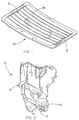
- One specific example involves the soldering of copper electrical terminals to the silver oxide painted defrost grid of an automobile's rear window, as shown in Figure 1.
- the rate of expansion for the glass is approximately .000004 inches per degree Fahrenheit, compared to .000009 inches per degree Fahrenheit for copper. This becomes a problem when the components are heated and cooled for the solder interface to bond the components together.
- the copper terminal will expand more than the glass.
- the solder joint will solidify while the terminal contracts a greater amount than the glass. This causes the fully cooled terminal to exert stress on the solder interface and the glass, reducing the mechanical strength of the connection.
- This problem is evident in several other applications, including the soldering of electrical connection pins to dense silica monolithic circuit chips.
- Prior art soldering methods tend to generate an excessive amount of heat when the heat for soldering is applied. Oftentimes, such soldering methods will generate sufficient heat to anneal tempered safety glass.
- Safety glass is tempered by first heating it to a critical temperature, then rapidly cooling it below a specific temperature. During the soldering process, the copper terminal is heated to cause the solder to flow, allowing the terminal's heat to be transferred to the adjacent glass. This becomes a problem when the terminal's solder temperature reaches or surpasses the annealing temperature of the glass. During cooling, the solder joint will solidify and the glass adjacent to the terminal becomes annealed. This annealed section of the glass will no longer be safety tempered and will no longer break into the small fragments required by Federal Regulations.
- a method and system for rapidly soldering a solder-coated terminal to a structure, having a different material composition than the terminal, is disclosed herein.
- the system comprises an intense heat source, such as an intermittent micro flame, a terminal gripper, having gripping jaws that are comprised of a heat-conductive material, and an optional air-jet cooler.
- the terminal is first secured between the jaws of the gripper, which are further adapted to selectively position the terminal closely adjacent the structure. Intense heat is applied to the terminal, in this instance being solder-coated, causing the solder to melt.
- the jaws are sufficient in thermal conductivity to serve as a heat sink, preventing the temperature of the terminal to significantly increase beyond the solder melting point during heating. This minimizes the transmission of heat from the terminal and layer of molten solder to the structure.
- the intense heat source is shut off and an optional jet of cool air is directed to the terminal. While the jet of air is cooling the terminal and layer of solder, the gripping jaws continue to remove residual heat from the terminal. These methods of cooling cause the solder joint to rapidly solidify.
- the time required to first melt the solder layer and then solidify the solder connection is short enough that the effect of the different rates of expansion between the terminal and the structure is greatly minimized. This is of great importance when the terminal-receiving structure is made of glass, such as tempered safety glass.
- the rapid heating and cooling time aid in preventing the safety glass from annealing and further allows for a stronger solder contact.
- a principal object of the invention is to provide an improved system for instantaneous heat sink soldering.
- Still another object of the invention is to provide a system for instantaneous heat sink soldering that reduces the heat transfer from a heated metallic terminal to a silica/glass structure.
- Still another object of the invention is to provide a system for instantaneous heat sink soldering that reduces the time required for solidifying the molten solder.
- Yet another object of the invention is to provide a system for instantaneous heat sink soldering that will not anneal a tempered glass structure to which a metallic terminal is soldered.
- Still another object of the invention is to provide a system for instantaneous heat sink soldering that minimizes the effect of the difference in the rate of expansion between a metallic terminal and a silica/glass structure when the two structures are soldered together.
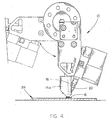
- the numeral 10 refers generally to the rapid heat-sink soldering system of this invention. As shown in Figures 2 - 4, the system 10 generally includes a gripper 12, a pair of generally parallel jaws 14a and 14b, ignition source 18, and an intense heat source 20. Although the foregoing elements could be incorporated into manually operated and automated devices, the following embodiment will be described as an automated device. Moreover, it is contemplated that the specific arrangement and type of elements described herein could be modified to implement the methods of soldering discussed herein.
- the air-actuated gripper 12 of the present embodiment is adapted to move the parallel jaws 14a and 14b toward or away from each other.
- the jaws 14a and 14b are adapted to grab, hold, and release a terminal 16 or other desired workpiece.
- the present embodiment uses a pair of jaws 14a and 14b for workpiece holding, it is contemplated that the number of jaws used in a particular embodiment will be dictated by the geometric shape of the chosen workpiece. For example, three or more jaws may be preferred when the workpiece has a round geometry, such as a snap terminal.
- the soldering mechanism of the present embodiment is comprised of an intermittent micro flame soldering tool 20, although it is contemplated that virtually any number of intense heat sources, such as electrical resistance, laser, friction, ultrasonic, induction, etc., could be employed in the device.
- Adjacent the soldering tool 20 is disposed an elongated, hollow structure 18 which is comprised of an electrically conductive material such as stainless steel, copper, nickel, or gold.
- the structure serves as both the ignition source for soldering tool 20 and as a conduit for air-jet cooling (discussed herein below).
- the ignition role of structure 18 is performed through the transmission of an electric current through structure 18.
- the present embodiment uses 8-mm high-tension insulated wire, which originates above structure 18 in the gripper 12, to produce the required electrical current.
- the electric current reaches the terminal end of structure 18 and ignites the fuel utilized by the intermittent micro flame 20.
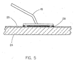
- terminal 16 comprises an integrated solder layer disposed on the surface of terminal 16 that is to be connected to the glass plate 24.
- the terminal 16 may also have a flux coating applied thereto.
- the soldering system 10 may also be comprised of a conventional apparatus for applying soldering related materials, such as a flux coating apparatus, solder paste application, or solder-wire feeder apparatus (none of which are depicted in Figures 1-5). In either case, however, the apparatus would apply the soldering materials to the terminal 16 immediately prior to the implementation of terminal 16.
- the parallel jaws 14a and 14b are drawn toward each other by the gripper 12 to grasp an individual terminal 16.
- the gripper 12 is positioned such that the parallel jaws 14a and 14b hold the terminal 16 at its point of use, as shown in Figure 4.
- the soldering tool is then operated such that it heats terminal 16 to a temperature which is sufficient to melt the solder disposed on the underside of terminal 16, thereby adhering terminal 16 to the silver oxide structure 26 located on glass plate 24.
- the intermittent micro flame 20 is then extinguished. Due to the intense heat used (approximately 5,400 degrees Fahrenheit) the total solder cycle is accomplished in approximately 2.0 seconds.
- the final solder "wetting" phase of the solder cycle is accomplished in approximately 0.2 seconds, which is typically an insufficient time to transfer heat from the terminal 16 to the glass plate 24 such that the glass plate 24 would anneal.
- Jaws 14a and 14b that support terminal 16 further serve as heat sinks for the present soldering device 10.
- Jaws 14a and 14b are preferably comprised of a conductive material such as stainless steel, copper, nickel, or gold. It is further preferred that the conductive material be non-corrosive, to prevent deterioration and or loss of thermal conductivity. When intense heat is applied to the terminal 16 to melt the solder, the excess heat is transmitted through jaws 14a and 14b, away from the glass plate 24.
- Air-jet cooling can also be provided to assist in the rapid cooling of the solder layer 28.
- a solenoid valve that is pneumatically connected to gripper 12 is actuated to force cool air into the system and through hollow structure 18, thereby providing a jet of cool air directly onto terminal 16.
- Alternative embodiments of the air-jet cooling method employ a compressed inert gas, such as nitrogen or carbon dioxide, or shielding gas, such as helium, that is directed to the terminal through hollow structure 18.
- a compressed inert gas such as nitrogen or carbon dioxide
- shielding gas such as helium
- Additional heat sinking could be accomplished by cooling jaws 14a and 14b with a system of internal cooling 22, which uses non-combustible gas or liquid that is channeled throughout the system, or external cooling source (not shown) that directs non-combustible gas or liquid to the external surface of the system.
- a system of internal cooling 22 which uses non-combustible gas or liquid that is channeled throughout the system, or external cooling source (not shown) that directs non-combustible gas or liquid to the external surface of the system.
- the post-solder cooling be accomplished by the heat sinks and/or the air-jet cooling system, rather than the transfer of heat through the glass plate 24.
- the soldering mechanism of the present invention is ideally suited to first apply a solder layer to the terminal 16 and then secure the terminal 16 to the glass plate 24.
- the jaws 14 a and 14b could be used to position the terminal 16 closely adjacent a solder-wire feeder apparatus, or other conventional device.
- Sufficient heat is then applied to the terminal 16, using the intermittent micro flame soldering tool 20, to melt the solder-wire.
- the surface tension of the molten solder will allow it to adhere to the lower surface of terminal 16.
- the molten solder rapidly cools (as described previously), forming a solid solder layer 28 along the lower surface of the terminal 16.
- the jaws 14a and 14b then position the terminal 16 closely adjacent the glass plate 24 and the soldering cycle described previously is commenced.
- the terminal 16 can also be soldered to the glass plate 24 when the glass is preheated to a temperature just below the temperature that the solder layer 28 becomes molten. This minimizes the effect of the difference in the rate of expansion between the terminal 16 and the glass plate 24, thereby reducing the stress that the terminal 16 will exert on the surface of the glass plate 24 once the solder layer 28 is fully cooled. This effectively improves the mechanical strength of the connection between terminal 16 and glass plate 24.
Landscapes
- Engineering & Computer Science (AREA)
- Mechanical Engineering (AREA)
- Electric Connection Of Electric Components To Printed Circuits (AREA)
- Molten Solder (AREA)
- Details Of Measuring And Other Instruments (AREA)
- Die Bonding (AREA)
- Joining Of Glass To Other Materials (AREA)
Applications Claiming Priority (2)
| Application Number | Priority Date | Filing Date | Title |
|---|---|---|---|
| US850398 | 1997-05-02 | ||
| US09/850,398 US6550668B2 (en) | 2001-05-07 | 2001-05-07 | Method and means for rapid heat-sink soldering |
Publications (3)
| Publication Number | Publication Date |
|---|---|
| EP1256409A2 true EP1256409A2 (de) | 2002-11-13 |
| EP1256409A3 EP1256409A3 (de) | 2004-05-06 |
| EP1256409B1 EP1256409B1 (de) | 2006-12-27 |
Family
ID=25308003
Family Applications (1)
| Application Number | Title | Priority Date | Filing Date |
|---|---|---|---|
| EP02007679A Expired - Lifetime EP1256409B1 (de) | 2001-05-07 | 2002-04-04 | Lötverfahren und -vorrichtung zum schnellen Kühlen |
Country Status (4)
| Country | Link |
|---|---|
| US (2) | US6550668B2 (de) |
| EP (1) | EP1256409B1 (de) |
| AT (1) | ATE349290T1 (de) |
| DE (1) | DE60217009T2 (de) |
Families Citing this family (6)
| Publication number | Priority date | Publication date | Assignee | Title |
|---|---|---|---|---|
| US6550668B2 (en) * | 2001-05-07 | 2003-04-22 | Larry J. Costa | Method and means for rapid heat-sink soldering |
| US7259351B2 (en) * | 2004-09-07 | 2007-08-21 | Federal-Mogul World Wide, Inc. | Heat treating assembly and method |
| JP2006156446A (ja) * | 2004-11-25 | 2006-06-15 | Shinka Jitsugyo Kk | 半田付け方法及び装置 |
| US8662374B2 (en) | 2010-12-16 | 2014-03-04 | Air Liquide Industrial U.S. Lp | Method for reduced cycle times in multi-pass welding while providing an inert atmosphere to the welding zone |
| US9036354B2 (en) * | 2013-01-15 | 2015-05-19 | Flextronics, Ap, Llc | Heat sink thermal press for phase change heat sink material |
| CN115446413B (zh) * | 2022-09-20 | 2023-08-22 | 六安煜晟电子科技有限公司 | 一种pcb钻头生产用钎焊装置 |
Family Cites Families (19)
| Publication number | Priority date | Publication date | Assignee | Title |
|---|---|---|---|---|
| GB141504A (en) * | 1919-08-23 | 1920-04-22 | Frank Jacob Wallis | Improvements relating to metal soldering, brazing and the like |
| US2506114A (en) * | 1947-07-05 | 1950-05-02 | John M Henry | Trigger-type gaseous blowtorch |
| US3458102A (en) * | 1967-08-09 | 1969-07-29 | Kulicke & Soffa Ind Inc | Semiconductor wafer pickup and bonding tool |
| US3640519A (en) * | 1969-08-13 | 1972-02-08 | William M Halstead | Handling and heat-dissipating device for electrical components |
| US3632973A (en) * | 1970-06-01 | 1972-01-04 | Honeywell Inf Systems | Soldering tool for removal and replacement of components having multiple soldered junctions |
| US3845606A (en) * | 1972-11-08 | 1974-11-05 | D Wilson | Package sealing in steam atmosphere |
| US3830681A (en) * | 1972-11-08 | 1974-08-20 | Fmc Corp | Package sealing in steam atmosphere |
| US3874443A (en) * | 1973-07-16 | 1975-04-01 | Joseph V Bayer | Heat dissipator |
| US4135573A (en) * | 1976-10-29 | 1979-01-23 | Sutter Melville B | Heat shielding tool |
| DD135026A1 (de) * | 1978-03-16 | 1979-04-04 | Herbert Bartuch | Verfahren zum hermetischen verschluss von bauelementegehaeusen der elektronik |
| US4889277A (en) * | 1987-02-05 | 1989-12-26 | Autosplice, Inc. | Method and apparatus for surface mounting terminals |
| US4530456A (en) * | 1983-05-04 | 1985-07-23 | Ppg Industries, Inc. | Method and apparatus for soldering by means of an industrial robot |
| JPS60191660A (ja) * | 1984-03-09 | 1985-09-30 | Sumitomo Electric Ind Ltd | ハンダ付け用治具 |
| US4632294A (en) * | 1984-12-20 | 1986-12-30 | International Business Machines Corporation | Process and apparatus for individual pin repair in a dense array of connector pins of an electronic packaging structure |
| US4962878A (en) * | 1987-02-18 | 1990-10-16 | Plato Products, Inc. | Desoldering aid |
| US5004491A (en) * | 1990-05-22 | 1991-04-02 | Glasstech, Inc. | Glass sheet forming method and apparatus utilizing lower full surface vacuum mold and upper ring mold |
| US5375757A (en) * | 1993-12-17 | 1994-12-27 | Dba Systems, Inc. | Fixture for supporting a cable conductor during a soldering operation |
| US6584670B2 (en) * | 2000-02-21 | 2003-07-01 | Larry J. Costa | Electrical terminal implementation device |
| US6550668B2 (en) * | 2001-05-07 | 2003-04-22 | Larry J. Costa | Method and means for rapid heat-sink soldering |
-
2001
- 2001-05-07 US US09/850,398 patent/US6550668B2/en not_active Expired - Fee Related
-
2002
- 2002-04-04 DE DE60217009T patent/DE60217009T2/de not_active Expired - Fee Related
- 2002-04-04 EP EP02007679A patent/EP1256409B1/de not_active Expired - Lifetime
- 2002-04-04 AT AT02007679T patent/ATE349290T1/de not_active IP Right Cessation
- 2002-12-24 US US10/329,654 patent/US6827253B2/en not_active Expired - Fee Related
Also Published As
| Publication number | Publication date |
|---|---|
| EP1256409B1 (de) | 2006-12-27 |
| ATE349290T1 (de) | 2007-01-15 |
| EP1256409A3 (de) | 2004-05-06 |
| DE60217009T2 (de) | 2007-07-19 |
| DE60217009D1 (de) | 2007-02-08 |
| US20030089761A1 (en) | 2003-05-15 |
| US20020162878A1 (en) | 2002-11-07 |
| US6550668B2 (en) | 2003-04-22 |
| US6827253B2 (en) | 2004-12-07 |
Similar Documents
| Publication | Publication Date | Title |
|---|---|---|
| EP1927420A2 (de) | Mikrowellenlötprozess | |
| US3529760A (en) | Flatpack installation and removal tool | |
| US6550668B2 (en) | Method and means for rapid heat-sink soldering | |
| CN104271299B (zh) | 用于技术上优化地实施钎焊连接的方法 | |
| US3930306A (en) | Process for attaching a lead member to a semiconductor device | |
| US6564458B1 (en) | Method for manufacturing a radiator | |
| US20210082868A1 (en) | Method of joining a surface-mount component to a substrate with solder that has been temporarily secured | |
| JP3110170B2 (ja) | 板状体のろう接方法 | |
| MX2007013181A (es) | Metodo para la formacion de una superficie de plata de ajuste apretado sobre una pieza de aluminio. | |
| JP2002307165A (ja) | ろう付け方法 | |
| JP2002346757A (ja) | プロジェクション溶接方法 | |
| JP5062710B2 (ja) | Au−Sn合金はんだペーストを用いた基板と素子の接合方法 | |
| JPH1034323A (ja) | こて半田付け方法及び装置 | |
| JP2006341304A (ja) | 異種金属接合法 | |
| US20190143726A1 (en) | Aluminum Based Solderable Contact | |
| JP2000216310A (ja) | ヒ―トシンクおよびその製造方法 | |
| Hata et al. | Interfacial reactions in Sn-57Bi-1Ag solder joints with Cu and Au metallization | |
| JP4079238B2 (ja) | 金属Na芯入り半田線 | |
| JPH0750585B2 (ja) | ヒューズ回路形成方法 | |
| CA2354546A1 (en) | Solder shaping process using a light source | |
| JP2812094B2 (ja) | 半田tabの構造ならびに半田tabのilb装置およびilb方法 | |
| JP2004265972A (ja) | 半導体装置およびその製造方法 | |
| JP2006100492A (ja) | 支持板上への電子部品の固着法 | |
| JP2005040823A (ja) | 半田付け装置と半田付け方法とコイル | |
| WO1991009699A1 (en) | Welding of solder frame to ceramic lid in semi-conductor packaging |
Legal Events
| Date | Code | Title | Description |
|---|---|---|---|
| PUAI | Public reference made under article 153(3) epc to a published international application that has entered the european phase |
Free format text: ORIGINAL CODE: 0009012 |
|
| 17P | Request for examination filed |
Effective date: 20020404 |
|
| AK | Designated contracting states |
Kind code of ref document: A2 Designated state(s): AT BE CH CY DE DK ES FI FR GB GR IE IT LI LU MC NL PT SE TR |
|
| AX | Request for extension of the european patent |
Free format text: AL;LT;LV;MK;RO;SI |
|
| PUAL | Search report despatched |
Free format text: ORIGINAL CODE: 0009013 |
|
| AK | Designated contracting states |
Kind code of ref document: A3 Designated state(s): AT BE CH CY DE DK ES FI FR GB GR IE IT LI LU MC NL PT SE TR |
|
| AX | Request for extension of the european patent |
Extension state: AL LT LV MK RO SI |
|
| RIC1 | Information provided on ipc code assigned before grant |
Ipc: 7H 05K 13/04 B Ipc: 7B 23K 37/04 B Ipc: 7B 23K 3/08 A Ipc: 7B 23K 1/005 B Ipc: 7B 23K 1/00 B Ipc: 7B 23K 3/04 B Ipc: 7F 23D 14/38 B |
|
| 17Q | First examination report despatched |
Effective date: 20041207 |
|
| AKX | Designation fees paid |
Designated state(s): AT BE CH CY DE DK ES FI FR GB GR IE IT LI LU MC NL PT SE TR |
|
| GRAP | Despatch of communication of intention to grant a patent |
Free format text: ORIGINAL CODE: EPIDOSNIGR1 |
|
| GRAS | Grant fee paid |
Free format text: ORIGINAL CODE: EPIDOSNIGR3 |
|
| GRAA | (expected) grant |
Free format text: ORIGINAL CODE: 0009210 |
|
| AK | Designated contracting states |
Kind code of ref document: B1 Designated state(s): AT BE CH CY DE DK ES FI FR GB GR IE IT LI LU MC NL PT SE TR |
|
| PG25 | Lapsed in a contracting state [announced via postgrant information from national office to epo] |
Ref country code: IT Free format text: LAPSE BECAUSE OF FAILURE TO SUBMIT A TRANSLATION OF THE DESCRIPTION OR TO PAY THE FEE WITHIN THE PRESCRIBED TIME-LIMIT;WARNING: LAPSES OF ITALIAN PATENTS WITH EFFECTIVE DATE BEFORE 2007 MAY HAVE OCCURRED AT ANY TIME BEFORE 2007. THE CORRECT EFFECTIVE DATE MAY BE DIFFERENT FROM THE ONE RECORDED. Effective date: 20061227 Ref country code: FI Free format text: LAPSE BECAUSE OF FAILURE TO SUBMIT A TRANSLATION OF THE DESCRIPTION OR TO PAY THE FEE WITHIN THE PRESCRIBED TIME-LIMIT Effective date: 20061227 Ref country code: NL Free format text: LAPSE BECAUSE OF FAILURE TO SUBMIT A TRANSLATION OF THE DESCRIPTION OR TO PAY THE FEE WITHIN THE PRESCRIBED TIME-LIMIT Effective date: 20061227 Ref country code: LI Free format text: LAPSE BECAUSE OF FAILURE TO SUBMIT A TRANSLATION OF THE DESCRIPTION OR TO PAY THE FEE WITHIN THE PRESCRIBED TIME-LIMIT Effective date: 20061227 Ref country code: CH Free format text: LAPSE BECAUSE OF FAILURE TO SUBMIT A TRANSLATION OF THE DESCRIPTION OR TO PAY THE FEE WITHIN THE PRESCRIBED TIME-LIMIT Effective date: 20061227 Ref country code: DK Free format text: LAPSE BECAUSE OF FAILURE TO SUBMIT A TRANSLATION OF THE DESCRIPTION OR TO PAY THE FEE WITHIN THE PRESCRIBED TIME-LIMIT Effective date: 20061227 Ref country code: AT Free format text: LAPSE BECAUSE OF FAILURE TO SUBMIT A TRANSLATION OF THE DESCRIPTION OR TO PAY THE FEE WITHIN THE PRESCRIBED TIME-LIMIT Effective date: 20061227 Ref country code: BE Free format text: LAPSE BECAUSE OF FAILURE TO SUBMIT A TRANSLATION OF THE DESCRIPTION OR TO PAY THE FEE WITHIN THE PRESCRIBED TIME-LIMIT Effective date: 20061227 |
|
| REG | Reference to a national code |
Ref country code: GB Ref legal event code: FG4D |
|
| REG | Reference to a national code |
Ref country code: IE Ref legal event code: FG4D |
|
| REF | Corresponds to: |
Ref document number: 60217009 Country of ref document: DE Date of ref document: 20070208 Kind code of ref document: P |
|
| PG25 | Lapsed in a contracting state [announced via postgrant information from national office to epo] |
Ref country code: SE Free format text: LAPSE BECAUSE OF FAILURE TO SUBMIT A TRANSLATION OF THE DESCRIPTION OR TO PAY THE FEE WITHIN THE PRESCRIBED TIME-LIMIT Effective date: 20070327 |
|
| PG25 | Lapsed in a contracting state [announced via postgrant information from national office to epo] |
Ref country code: ES Free format text: LAPSE BECAUSE OF FAILURE TO SUBMIT A TRANSLATION OF THE DESCRIPTION OR TO PAY THE FEE WITHIN THE PRESCRIBED TIME-LIMIT Effective date: 20070407 |
|
| PG25 | Lapsed in a contracting state [announced via postgrant information from national office to epo] |
Ref country code: PT Free format text: LAPSE BECAUSE OF FAILURE TO SUBMIT A TRANSLATION OF THE DESCRIPTION OR TO PAY THE FEE WITHIN THE PRESCRIBED TIME-LIMIT Effective date: 20070528 |
|
| NLV1 | Nl: lapsed or annulled due to failure to fulfill the requirements of art. 29p and 29m of the patents act | ||
| REG | Reference to a national code |
Ref country code: CH Ref legal event code: PL |
|
| EN | Fr: translation not filed | ||
| PLBE | No opposition filed within time limit |
Free format text: ORIGINAL CODE: 0009261 |
|
| STAA | Information on the status of an ep patent application or granted ep patent |
Free format text: STATUS: NO OPPOSITION FILED WITHIN TIME LIMIT |
|
| 26N | No opposition filed |
Effective date: 20070928 |
|
| PG25 | Lapsed in a contracting state [announced via postgrant information from national office to epo] |
Ref country code: GR Free format text: LAPSE BECAUSE OF FAILURE TO SUBMIT A TRANSLATION OF THE DESCRIPTION OR TO PAY THE FEE WITHIN THE PRESCRIBED TIME-LIMIT Effective date: 20070328 Ref country code: FR Free format text: LAPSE BECAUSE OF FAILURE TO SUBMIT A TRANSLATION OF THE DESCRIPTION OR TO PAY THE FEE WITHIN THE PRESCRIBED TIME-LIMIT Effective date: 20070817 |
|
| PG25 | Lapsed in a contracting state [announced via postgrant information from national office to epo] |
Ref country code: IE Free format text: LAPSE BECAUSE OF NON-PAYMENT OF DUE FEES Effective date: 20070404 |
|
| PGFP | Annual fee paid to national office [announced via postgrant information from national office to epo] |
Ref country code: DE Payment date: 20080411 Year of fee payment: 7 |
|
| PG25 | Lapsed in a contracting state [announced via postgrant information from national office to epo] |
Ref country code: FR Free format text: LAPSE BECAUSE OF FAILURE TO SUBMIT A TRANSLATION OF THE DESCRIPTION OR TO PAY THE FEE WITHIN THE PRESCRIBED TIME-LIMIT Effective date: 20061227 |
|
| PGFP | Annual fee paid to national office [announced via postgrant information from national office to epo] |
Ref country code: GB Payment date: 20080409 Year of fee payment: 7 |
|
| PG25 | Lapsed in a contracting state [announced via postgrant information from national office to epo] |
Ref country code: MC Free format text: LAPSE BECAUSE OF NON-PAYMENT OF DUE FEES Effective date: 20070430 |
|
| PG25 | Lapsed in a contracting state [announced via postgrant information from national office to epo] |
Ref country code: CY Free format text: LAPSE BECAUSE OF FAILURE TO SUBMIT A TRANSLATION OF THE DESCRIPTION OR TO PAY THE FEE WITHIN THE PRESCRIBED TIME-LIMIT Effective date: 20061227 Ref country code: LU Free format text: LAPSE BECAUSE OF NON-PAYMENT OF DUE FEES Effective date: 20070404 |
|
| PG25 | Lapsed in a contracting state [announced via postgrant information from national office to epo] |
Ref country code: TR Free format text: LAPSE BECAUSE OF FAILURE TO SUBMIT A TRANSLATION OF THE DESCRIPTION OR TO PAY THE FEE WITHIN THE PRESCRIBED TIME-LIMIT Effective date: 20061227 |
|
| GBPC | Gb: european patent ceased through non-payment of renewal fee |
Effective date: 20090404 |
|
| PG25 | Lapsed in a contracting state [announced via postgrant information from national office to epo] |
Ref country code: DE Free format text: LAPSE BECAUSE OF NON-PAYMENT OF DUE FEES Effective date: 20091103 |
|
| PG25 | Lapsed in a contracting state [announced via postgrant information from national office to epo] |
Ref country code: GB Free format text: LAPSE BECAUSE OF NON-PAYMENT OF DUE FEES Effective date: 20090404 |