EP1279663A1 - Procédé pour synthèse de l'urée - Google Patents
Procédé pour synthèse de l'urée Download PDFInfo
- Publication number
- EP1279663A1 EP1279663A1 EP02015611A EP02015611A EP1279663A1 EP 1279663 A1 EP1279663 A1 EP 1279663A1 EP 02015611 A EP02015611 A EP 02015611A EP 02015611 A EP02015611 A EP 02015611A EP 1279663 A1 EP1279663 A1 EP 1279663A1
- Authority
- EP
- European Patent Office
- Prior art keywords
- urea synthesis
- mixed gas
- solution
- urea
- carbon dioxide
- Prior art date
- Legal status (The legal status is an assumption and is not a legal conclusion. Google has not performed a legal analysis and makes no representation as to the accuracy of the status listed.)
- Granted
Links
Images


Classifications
-
- C—CHEMISTRY; METALLURGY
- C07—ORGANIC CHEMISTRY
- C07C—ACYCLIC OR CARBOCYCLIC COMPOUNDS
- C07C273/00—Preparation of urea or its derivatives, i.e. compounds containing any of the groups, the nitrogen atoms not being part of nitro or nitroso groups
- C07C273/02—Preparation of urea or its derivatives, i.e. compounds containing any of the groups, the nitrogen atoms not being part of nitro or nitroso groups of urea, its salts, complexes or addition compounds
- C07C273/04—Preparation of urea or its derivatives, i.e. compounds containing any of the groups, the nitrogen atoms not being part of nitro or nitroso groups of urea, its salts, complexes or addition compounds from carbon dioxide and ammonia
Definitions
- the present invention relates to an improved urea synthesis process, and more particularly to a urea synthesis process wherein heat is recovered and utilized for decomposing unreacted ammonium carbamate contained in a urea solution.
- a mixed gas separated from a urea synthesis solution in a stripper 2 is divided and supplied separately to the tube side of each of two shell-and-tube type vertical condensers 9a and 9b which are located in parallel, through lines 18, and 32 and 33 so that the mixed gas is condensed .
- the vertical condenser 9a water is supplied to a shell side thereof through a line 36 and low pressure steam is generated through a line 37 by heat generated by condensation of the mixed gas.
- a urea solution comprising unseparated unreacted ammonia and unreacted carbon dioxide fed from the stripper 2 is heated at a shell side thereof by heat generated by condensation of the mixed gas, so that the heat is used as a heat source in a step of separating unreacted ammonia and unreacted carbon dioxide in a urea synthesis process.
- the condensation temperature of the mixed gas comprising ammonia, carbon dioxide and water, which is brought from the stripper 2 is 170°C to 180°C. Since this temperature is higher than the temperature of the low pressure steam, which is 150°C to 155°C, the temperature of a heated side can be kept higher and thereby heat recovery can efficiently be carried out.
- a medium pressure decomposer, reboiler or falling film heater (not shown) in stead of the vertical condenser 9b to recover heat in the same manner.
- the mixed gas is supplied to the tube side of each of the vertical condensers 9a and 9b whereas a cooling medium is supplied to the shell side, and therefore this method is not structurally suitable for dividing the shell side, supplying a plurality of cooling mediums and performing heat exchange with each of them.
- the mixed gas discharged from the stripper 2 to the line 18 is supplied to a vertical condensation reactor 4 having a cooling tube 23 therein and is then condensed, and the obtained heat of condensation is recovered by generating a low pressure steam in the cooling tube 23.
- the generated low pressure steam is used in a step of separating unreacted ammonia and carbon dioxide under a low pressure or in a step of concentrating a urea solution in a urea synthesis process.
- the present inventors have found that, when the heat of condensation of a mixed gas of ammonia and carbon dioxide having a high temperature, that is, a high temperature of 170°C to 180°C, is directly used as a heat source in a step of separating unreacted ammonia and carbon dioxide, without generating a low pressure steam, in other words, without reducing the temperature to 150°C to 155°C that is the temperature of the low pressure steam, heat transfer efficiency is substantially improved and the heat transfer area required in a urea synthesis process as a whole is sharply reduced, thereby completing the present invention.
- the present invention provides the following urea synthesis process:
- a urea synthesis process which comprises the steps of, reacting raw material ammonia and carbon dioxide in a urea synthesis column at a urea synthesis temperature and under a urea synthesis pressure; contacting the resulting urea synthesis solution comprising urea, unreacted ammonia, unreacted carbon dioxide and water with at least a portion of the raw material carbon dioxide under heating in a stripper under a pressure approximately equal to the urea synthesis pressure, thereby separating unreacted ammonia and unreacted carbon dioxide as a mixed gas of ammonia, carbon dioxide and water; feeding the mixed gas to a shell side of a vertical condensation reactor having a cooling tube therein to contact the mixed gas with an absorption medium under cooling for condensation of the mixed gas; and recycling the resulting condensate to the urea synthesis column so as to obtain a urea synthesis solution comprising unreacted ammonia and unreacted carbon dioxide that have not been separated, wherein the urea synthesis solution separated from the mixed gas in the
- the urea synthesis solution comprising unseparated unreacted ammonia and unreacted carbon dioxide discharged from the stripper is decompressed to a pressure lower than the urea synthesis pressure, and is then fed to the cooling tube of the vertical condensation reactor.
- the urea synthesis solution comprising unseparated unreacted ammonia and unreacted carbon dioxide discharged from the stripper is decompressed and fed to a medium pressure separator wherein a portion of unreacted ammonia and unreacted carbon dioxide contained in the urea synthesis solution is separated, and then the resulting solution is fed to the cooling tube of the vertical condensation reactor.
- the urea synthesis solution fed to the cooling tube side of the vertical condensation reactor is preferably heated to a temperature of 150°C to 170°C by the heat of condensation of the mixed gas fed to the vertical condensation reactor.
- the cooling tube of the vertical condensation reactor is preferably a U-shaped tube having multi channels.
- a urea synthesis solution (hereinafter, simply referred to as aurea solution) containing remaining unreacted ammonia and unreacted carbon dioxide discharged from a bottom part of a stripper is preferably fed to the cooling tube of a vertical condenser after being decompressed through a reducing valve.
- aurea solution a urea synthesis solution
- the pressure is reduced to a medium pressure within a range of preferably about 0.01 to 3.0 MPa, more preferably about 1.0 to 2.5 MPa, and particularly preferably about 1.5 to 2.0 MPa.
- the urea solution the pressure of which is reduced to a medium pressure, leaves a mixed gas comprising ammonia, carbon dioxide and water separated from the solution by decompression, in a medium pressure separator, before entering the cooling tube.
- a mixed gas comprising ammonia, carbon dioxide and water separated from the solution by decompression, in a medium pressure separator, before entering the cooling tube.
- a vertical condensation reactor is preferably a vertical heat exchanger comprising a U-shaped cooling tube having multi channels.
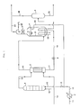
- FIG. 1 is a process flow sheet showing one embodiment of the present invention.
- a raw material ammonia after the pressure is raised to about 25 MPa, is fed to a heat exchanger 7 through a line 11, and heated to about 175°C with a recovered low pressure steam and a condensate of a high pressure steam. Subsequently, the ammonia is fed to an ejector 10 through a line 12 and then expanded to the urea synthesis pressure. A condensate fed from a down pipe 22 is sucked to the ejector, and then it is fed to a urea synthesis column 1 together with the ammonia through a line 13 .
- the raw material carbon dioxide and anti-corrosive air are supplied to a bottom part of the stripper 2 through a line 14, but a portion of them is fed to the urea synthesis column 1 though the line 15.
- urea synthesis column 1 While ammonia, carbon dioxide and anti-corrosive air are going up in the urea synthesis column 1, which is operated under a pressure of 13 to 25 MPa at a temperature of 180°C to 200°C, a urea synthesis reaction proceeds. After completion of the reaction, the urea synthesis solution is discharged from a top part of the urea synthesis column 1 to a line 16, and is then fed to a top part of the stripper 2.
- unreacted ammonium carbamate (unreacted ammonia and unreacted carbon dioxide) contained in the urea synthesis solution are thermally decomposed and separated as a mixed gas comprising ammonia, carbon dioxide, water and inert gas.
- the above mixed gas is fed from the top part of the stripper 2 to a shell side of the vertical condensation reactor 4 through the line 18, while the urea synthesis solution comprising unseparated unreacted ammonia and unreacted carbon dioxide is discharged from the bottom part of the stripper 2 to a line 17 and then fed to a cooling tube side of the vertical condensation reactor 4 after decompressed through a reducing valve 8 to a pressure of 1.0 to 2.5 MPa.
- the pressure of a recovery solution (a solution obtained by separating the unreacted ammonium carbamate contained in the urea synthesis solution fed from the stripper 2 as a mixed gas comprising ammonia, carbon dioxide and water under a medium and/or low pressure and absorbing the mixed gas into water, diluted ammonia water or the like), which is fed as an absorption medium through a line 20, is raised to about 13.5 to 25.5 MPa at a temperature of about 110°C, and then fed to a packed part 5 installed on a top part of the vertical condensation reactor 4.
- the packed part 5 is operated under a pressure of 13 to 25 MPa at a temperature of 160°C to 190°C.
- An absorption solution discharged from a bottom part of the packed part 5 flows down from a down pipe 21 to a bottom part of the vertical condensation reactor 4, and then contacted with the mixed gas brought from the line 18 under cooling so as to absorb and condense the mixed gas.
- the shell side of the vertical condensation reactor 4 is filled with the above absorption solution and condensate (hereinafter, both solutions are collectively referred to as a condensate) fed from the packed part 5, and heat of condensation (absorption heat) is removed by a cooling medium, which is fed to a cooling tube 19 and, if desired, to a cooling tube 23.
- the vertical condensation reactor 4 is a vertical heat exchanger comprising a U-shaped cooling tube having multi channels, which not only heats a urea solution supplied from a stripper but also preferably supplies water to other channels to generate low pressure steam. Moreover, this vertical condensation reactor 4 can easily heat other cooling mediums such as a raw material liquid ammonia.
- the temperature of the shell side of the vertical condensation reactor 4 is controlled at 170°C to 190°C, and this control of temperature can be carried out by removing the heat of condensation of a mixed gas preferably by heating two cooling mediums, for example, by heating the urea synthesis solution and generating steam.
- the condensate in the shell side of the vertical condensation reactor 4 is fed to a sucking side of the ejector 10 through the down pipe 22 having an opening on the top part of the shell side.
- the urea synthesis solution supplied to the cooling tube side of the vertical condensation reactor 4 through a line 19 is heated to a temperature of 150°C to 170°C, which is desirable to decompose unreacted ammonium carbamate under a medium pressure.
- the heat required for medium pressure decomposition is provided from the heat of condensation generated in the vertical condensation reactor 4, and accordingly there is no need for the heating of a medium pressure decomposer 6.
- the heated urea synthesis solution is fed to the medium pressure decomposer 6 operated preferably under a pressureof 1.0 to 2.5, more preferably under a pressure of 1.5 to 2.0 MPa at a temperature of 150°C to 170°C to separate unseparated unreacted ammonium carbamate.
- the urea solution comprising almost no unreacted ammonium carbamate is fed through a line 25 to a low pressure decomposer (not shown) for the next step.
- the mixed gas separated from the urea synthesis solution is subjected to a recovering step through a line 26.
- the condensate generated by absorbing the mixed gas supplied from the line 18 flows down through the down pipe 22 by gravitation, and after the pressure is raised by an ejector 10, the condensate is fed to the urea synthesis column 1. On the other hand, the mixed gas which is not absorbed is subjected to the next step through a line 24.
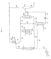
- FIG. 2 is a process flow sheet showing another embodiment of the present invention.
- a urea solution separated from a mixed gas in the stripper 2 is supplied to the medium pressure separator 3, and after the mixed gas contained in the urea solution is further separated, the resulting solution is fed to the cooling tube of the vertical condensation reactor 4.
- the stripper 2 is operated under a pressure of 13 to 25 MPa at a temperature of 160°C to 200°C, and therein, unreacted ammonium carbamate contained in the urea synthesis solution is decomposed into ammonia and carbon dioxide by stripping with a raw material carbon dioxide, and then separated as a mixed gas comprising ammonia, carbon dioxide, water and inert gas.
- This mixed gas is fed from the top part of the stripper 2 to the shell side of the vertical condensation reactor 4 through the line 18, while the urea solution comprising unseparated unreacted ammonia and unreacted carbon dioxide is discharged from the bottom part of the stripper 2 to the line 17, decompressed through reducing valve 8, and then fed to the medium pressure separator 3.
- the medium pressure separator 3 is operated under a pressure of 1.5 to 2.5 MPa at a temperature of 120°C to 150°C. Accordingly, the urea synthesis solution falls from the operation pressure and temperature of the stripper 2 to the operation pressure and temperature of the medium pressure separator 3 by adiabatic expansion and becomes two phases of gas and liquid, and thereby the gas contained in the urea solution is separated.
- the urea solution obtained by separation of gas from the urea synthesis solution is fed from the bottom part of the vertical condensation reactor 4 to the cooling tube side through the line 19, while the mixed gas separated from the urea solution is fed to a recovering step through a line 27.
- the pressure of a recovery solution which is supplied as an absorption medium from the line 20, is raised to about 13.5 to 25.5 MPa at a temperature of about 110°C, and then fed to the packed part 5 installed on the top part of the vertical condensation reactor 4.
- the packed part 5 is operated under a pressure of 13 to 25 MPa at a temperature of 160°C to 190°C, and the solution accumulated in the bottom part of the filling part 5 is fed to the bottom part of the vertical condensation reactor 4 through the down pipe 21.
- the shell side of the vertical condensation reactor 4 is filled with the absorption solution and condensate delivered from the filling part 5, and the mixed gas is absorbed and condensed and the heat of condensation is removed by the cooling tubes 19 and 23.
- the urea solution Since, in the medium pressure separator, the urea solution has a pressure lower than the pressure in the synthesis column and is separated into the two phases of gas and liquid, if it is directly fed to the cooling tubes, the distribution of the urea solution in each tube tends to be uneven. However, if the urea solution is fed to the vertical condensation reactor 4 after the mixed gas contained in the urea solution is separated in the medium pressure separator 3, the solution is evenly distributed to cooling tubes, and heat exchange efficiency is improved.
- the gas contained in the urea synthesis solution is separated in the medium pressure separator 3 and only the liquid phase is fed to the cooling tube side.
- FIG. 1 and FIG. 2 can selectively be used as appropriate depending on the cost of the cooling tubes and the medium pressure separator 3.
- the cost of the equipment can be reduced somewhat by installation of the medium pressure separator 3.
- the heat transfer area required for heating a urea solution from a stripper to 155°C was found to be 285 m 2 . This was about 2/10 to 3/10 of the heat transfer area required in the prior art.
- the material balance is shown in Table 1.
- the vertical column represents the number of each line shown in FIG. 1, and the horizontal column represents the pressure, the temperature, the flow rate and the composition of a substance flowing through each line.
- the shell side temperature, the tube side temperature, the total heat transfer coefficient and the required heat transfer area of a vertical condensation reactor are shown in Table 3.
- the heat transfer area required for heating a urea solution from a stripper to 155°C after decompression was found to be 252 m 2 . This was about 2/10 to 3/10 of the heat transfer area required in the prior art.
- the material balance is shown in Table 1.
- the vertical column represents the number of each line shown in FIG. 2, and the horizontal column represents the pressure, the temperature, the flow rate and the composition of a substance flowing through each line.
- the shell side temperature, the tube side temperature, the total heat transfer coefficient and the required heat transfer area of a vertical condensation reactor are shown in Table 3.
- Example 3 differing from Example 1, since only the urea synthesis solution is fed to the tube side after the separation of a mixed gas and urea solution, it became unnecessary to raise the temperature of the mixed gas. In addition, since the urea synthesis solution was evenly distributed, the total heat transfer coefficient was further improved and the heat transfer area was further reduced.
- the material balance is shown in Table 2.
- the vertical column represents the number of each line shown in FIG. 3, and the horizontal column represents the pressure, the temperature, the flow rate and the composition of a substance flowing through each line.
- the shell side temperature, the tube side temperature, the total heat transfer coefficient and the required heat transfer area of a vertical condensation reactor are shown in Table 3.
- the heat transfer area required for heating a urea solution from a stripper to 155°C after decompression was found to be 1,028 m 2 , since the total heat transfer coefficient was low due to falling film type condensation.
- the material balance is shown in Table 2.
- the vertical column represents the number of each line shown in FIG. 4, and the horizontal column represents the pressure, the temperature, the flow rate and the composition of a substance flowing through each line.
- the shell side temperature, the tube side temperature, the total heat transfer coefficient and the required heat transfer area of a vertical condensation reactor are shown in Table 3.
- the heat of condensation of a mixed gas under a urea synthesis pressure is used as the heat source for medium pressure decomposition in the prior art process, the process becomes complicated in that the number of devices increases and the division of the mixed gas is required.
- a vertical condensation reactor which is a vertical heat exchanger having a U-shaped cooling tube is used, it becomes possible to simultaneously carry out both the generation of a low pressure steam and the heating of a urea synthesis solution by dividing the tube sheet, without increasing the number of devices or without dividing the gas.
- other cooling mediums such as liquid ammonia and recovery solution can easily be introduced by dividing the tube sheet.
Landscapes
- Chemical & Material Sciences (AREA)
- Organic Chemistry (AREA)
- Organic Low-Molecular-Weight Compounds And Preparation Thereof (AREA)
Priority Applications (1)
| Application Number | Priority Date | Filing Date | Title |
|---|---|---|---|
| DE60201384T DE60201384T3 (de) | 2001-07-23 | 2002-07-15 | Verfahren zur Harnstoffsynthese |
Applications Claiming Priority (2)
| Application Number | Priority Date | Filing Date | Title |
|---|---|---|---|
| JP2001221656 | 2001-07-23 | ||
| JP2001221656 | 2001-07-23 |
Publications (3)
| Publication Number | Publication Date |
|---|---|
| EP1279663A1 true EP1279663A1 (fr) | 2003-01-29 |
| EP1279663B1 EP1279663B1 (fr) | 2004-09-29 |
| EP1279663B2 EP1279663B2 (fr) | 2010-07-28 |
Family
ID=19055293
Family Applications (1)
| Application Number | Title | Priority Date | Filing Date |
|---|---|---|---|
| EP02015611A Expired - Lifetime EP1279663B2 (fr) | 2001-07-23 | 2002-07-15 | Procédé pour synthèse de l'urée |
Country Status (4)
| Country | Link |
|---|---|
| US (1) | US6518457B1 (fr) |
| EP (1) | EP1279663B2 (fr) |
| BR (1) | BR0202786B1 (fr) |
| DE (1) | DE60201384T3 (fr) |
Cited By (8)
| Publication number | Priority date | Publication date | Assignee | Title |
|---|---|---|---|---|
| WO2006118071A1 (fr) | 2005-04-27 | 2006-11-09 | Toyo Engineering Corporation | Appareil pour la synthèse d'urée et procédé d'amélioration de celui-ci |
| EP2343274A1 (fr) * | 2010-01-07 | 2011-07-13 | Stamicarbon B.V. | Procédé d'extraction d'urée pour la production d'urée |
| CN102816091A (zh) * | 2011-06-10 | 2012-12-12 | 安徽省科捷再生能源利用有限公司 | 水溶液全循环尿素节能生产工艺 |
| EP2844641A1 (fr) | 2012-05-03 | 2015-03-11 | Stamicarbon B.V. | Procédé et appareil de production d'urée à partir d'ammoniac et de dioxyde de carbone |
| CN108026033A (zh) * | 2015-09-08 | 2018-05-11 | 东洋工程株式会社 | 尿素制造方法以及尿素制造装置 |
| CN108658811A (zh) * | 2018-06-28 | 2018-10-16 | 福州海蓝环保科技有限公司 | 一种车用尿素的制备方法及制备系统 |
| CN110639461A (zh) * | 2018-06-26 | 2020-01-03 | 浙江理工大学 | 降膜式脱挥器及其降膜元件 |
| WO2020183717A1 (fr) | 2019-03-14 | 2020-09-17 | Toyo Engineering Corporation | Procédé et appareil pour la production d'urée |
Families Citing this family (5)
| Publication number | Priority date | Publication date | Assignee | Title |
|---|---|---|---|---|
| JP4994226B2 (ja) * | 2005-04-27 | 2012-08-08 | 東洋エンジニアリング株式会社 | 尿素合成装置 |
| EP2153880A1 (fr) * | 2008-07-31 | 2010-02-17 | Urea Casale S.A. | Procédé et installation pour la production d'une solution d'urée à utiliser dans le procédé SCR pour la réduction de Nox |
| JP5564497B2 (ja) | 2009-05-28 | 2014-07-30 | 東洋エンジニアリング株式会社 | カルバミン酸アンモニウム水溶液の分析方法および未反応ガス吸収槽の運転方法 |
| CN111278804B (zh) | 2017-10-27 | 2021-07-20 | 斯塔米卡邦有限公司 | 高压氨基甲酸盐冷凝器 |
| CN108658810B (zh) * | 2018-06-28 | 2020-12-25 | 福州海蓝环保科技有限公司 | 一种车用尿素生产系统 |
Citations (1)
| Publication number | Priority date | Publication date | Assignee | Title |
|---|---|---|---|---|
| EP0834501A2 (fr) * | 1996-10-07 | 1998-04-08 | Toyo Engineering Corporation | Procédé amélioré de préparation de l'urée et appareil pour celà |
Family Cites Families (4)
| Publication number | Priority date | Publication date | Assignee | Title |
|---|---|---|---|---|
| JPS61109760A (ja) | 1984-11-02 | 1986-05-28 | Toyo Eng Corp | 尿素製造法 |
| JPS6215070A (ja) | 1985-07-12 | 1987-01-23 | Honda Motor Co Ltd | クランクピン研削盤における位相割出し装置 |
| NL8502227A (nl) † | 1985-08-12 | 1987-03-02 | Unie Van Kunstmestfab Bv | Werkwijze voor de bereiding van ureum. |
| NL1003923C2 (nl) * | 1996-08-30 | 1998-03-04 | Dsm Nv | Werkwijze voor de bereiding van ureum. |
-
2002
- 2002-07-15 DE DE60201384T patent/DE60201384T3/de not_active Expired - Lifetime
- 2002-07-15 EP EP02015611A patent/EP1279663B2/fr not_active Expired - Lifetime
- 2002-07-22 US US10/198,962 patent/US6518457B1/en not_active Expired - Lifetime
- 2002-07-22 BR BRPI0202786-0A patent/BR0202786B1/pt not_active IP Right Cessation
Patent Citations (2)
| Publication number | Priority date | Publication date | Assignee | Title |
|---|---|---|---|---|
| EP0834501A2 (fr) * | 1996-10-07 | 1998-04-08 | Toyo Engineering Corporation | Procédé amélioré de préparation de l'urée et appareil pour celà |
| JPH10182587A (ja) * | 1996-10-07 | 1998-07-07 | Toyo Eng Corp | 改良された尿素合成方法および装置 |
Cited By (16)
| Publication number | Priority date | Publication date | Assignee | Title |
|---|---|---|---|---|
| WO2006118071A1 (fr) | 2005-04-27 | 2006-11-09 | Toyo Engineering Corporation | Appareil pour la synthèse d'urée et procédé d'amélioration de celui-ci |
| EA024085B1 (ru) * | 2010-01-07 | 2016-08-31 | Стамикарбон Б.В. | Способ и установка для производства мочевины |
| EP2343274A1 (fr) * | 2010-01-07 | 2011-07-13 | Stamicarbon B.V. | Procédé d'extraction d'urée pour la production d'urée |
| WO2011084060A1 (fr) * | 2010-01-07 | 2011-07-14 | Stamicarbon B.V. | Procédé de séquestration d'urée pour la production d'urée |
| CN102712581A (zh) * | 2010-01-07 | 2012-10-03 | 斯塔米卡邦有限公司 | 用于生产尿素的尿素汽提方法 |
| CN102712581B (zh) * | 2010-01-07 | 2014-11-05 | 斯塔米卡邦有限公司 | 用于生产尿素的尿素汽提方法 |
| US9447032B2 (en) | 2010-01-07 | 2016-09-20 | Stamicarbon B.V. | Urea stripping process for the production of urea |
| CN102816091A (zh) * | 2011-06-10 | 2012-12-12 | 安徽省科捷再生能源利用有限公司 | 水溶液全循环尿素节能生产工艺 |
| EP2844641A1 (fr) | 2012-05-03 | 2015-03-11 | Stamicarbon B.V. | Procédé et appareil de production d'urée à partir d'ammoniac et de dioxyde de carbone |
| US9505712B2 (en) | 2012-05-03 | 2016-11-29 | Stamicarbon B.V. | Method and apparatus for the production of urea from ammonia and carbon dioxide |
| CN108026033A (zh) * | 2015-09-08 | 2018-05-11 | 东洋工程株式会社 | 尿素制造方法以及尿素制造装置 |
| CN108026033B (zh) * | 2015-09-08 | 2020-11-20 | 东洋工程株式会社 | 尿素制造方法以及尿素制造装置 |
| CN110639461A (zh) * | 2018-06-26 | 2020-01-03 | 浙江理工大学 | 降膜式脱挥器及其降膜元件 |
| CN110639461B (zh) * | 2018-06-26 | 2024-04-09 | 浙江理工大学 | 降膜式脱挥器及其降膜元件 |
| CN108658811A (zh) * | 2018-06-28 | 2018-10-16 | 福州海蓝环保科技有限公司 | 一种车用尿素的制备方法及制备系统 |
| WO2020183717A1 (fr) | 2019-03-14 | 2020-09-17 | Toyo Engineering Corporation | Procédé et appareil pour la production d'urée |
Also Published As
| Publication number | Publication date |
|---|---|
| EP1279663B2 (fr) | 2010-07-28 |
| BR0202786A (pt) | 2003-05-20 |
| DE60201384D1 (de) | 2004-11-04 |
| US6518457B1 (en) | 2003-02-11 |
| DE60201384T3 (de) | 2012-01-26 |
| BR0202786B1 (pt) | 2012-06-26 |
| EP1279663B1 (fr) | 2004-09-29 |
| DE60201384T2 (de) | 2005-03-10 |
Similar Documents
| Publication | Publication Date | Title |
|---|---|---|
| TWI471295B (zh) | 製備異氰酸酯之方法 | |
| EP1279663B2 (fr) | Procédé pour synthèse de l'urée | |
| EP1876171B1 (fr) | Appareil pour la synthèse d'urée et procédé d'amélioration de celui-ci | |
| JP6762306B2 (ja) | 尿素製造方法及び尿素製造装置 | |
| EP0752416B1 (fr) | Procédé et appareil pour récupérer des produits condensables des vapeurs résultants d'un évaporateur à vide de la synthèse d'urée | |
| EA033625B1 (ru) | Производство карбамида с контролируемым содержанием биурета | |
| EP2521710B1 (fr) | Procédé d'extraction d'urée pour la production d'urée | |
| EP0504966A1 (fr) | Procédé pour la production d'urée à haute efficacité en énergie | |
| US6476262B2 (en) | Urea synthesis process and apparatus | |
| US8158823B2 (en) | Method for the modernization of a urea production plant | |
| JP4627959B2 (ja) | 尿素合成方法 | |
| CN113574049A (zh) | 尿素制备的方法和装置 | |
| EP1876170B1 (fr) | Appareil pour la synthèse d'urée | |
| KR102673700B1 (ko) | 이소프로필 알코올 제조방법 | |
| EP0145054B1 (fr) | Procédé pour la préparation de l'urée | |
| EP1289943B1 (fr) | Procede pour decomposer une solution aqueuse de carbamate provenant d'une section de recuperation d'une usine de production d'uree | |
| CN87107799A (zh) | 分离未转变原料的方法 | |
| AU718170B2 (en) | Improved urea synthesis process and apparatus therefor | |
| CN120379964A (zh) | 采用hp co2汽提的联产的尿素三聚氰胺生产 | |
| JPS58203956A (ja) | 尿素合成法の改良 | |
| JPS5812270B2 (ja) | 尿素合成方法 |
Legal Events
| Date | Code | Title | Description |
|---|---|---|---|
| PUAI | Public reference made under article 153(3) epc to a published international application that has entered the european phase |
Free format text: ORIGINAL CODE: 0009012 |
|
| AK | Designated contracting states |
Designated state(s): AT BE BG CH CY CZ DE DK EE ES FI FR GB GR IE IT LI LU MC NL PT SE SK TR |
|
| AX | Request for extension of the european patent |
Extension state: AL LT LV MK RO SI |
|
| 17P | Request for examination filed |
Effective date: 20030722 |
|
| AKX | Designation fees paid |
Designated state(s): CH DE IT LI NL |
|
| GRAP | Despatch of communication of intention to grant a patent |
Free format text: ORIGINAL CODE: EPIDOSNIGR1 |
|
| GRAS | Grant fee paid |
Free format text: ORIGINAL CODE: EPIDOSNIGR3 |
|
| GRAA | (expected) grant |
Free format text: ORIGINAL CODE: 0009210 |
|
| AK | Designated contracting states |
Kind code of ref document: B1 Designated state(s): CH DE IT LI NL |
|
| REG | Reference to a national code |
Ref country code: CH Ref legal event code: EP |
|
| REG | Reference to a national code |
Ref country code: IE Ref legal event code: FG4D |
|
| REF | Corresponds to: |
Ref document number: 60201384 Country of ref document: DE Date of ref document: 20041104 Kind code of ref document: P |
|
| REG | Reference to a national code |
Ref country code: CH Ref legal event code: NV Representative=s name: R. A. EGLI & CO. PATENTANWAELTE |
|
| PLBI | Opposition filed |
Free format text: ORIGINAL CODE: 0009260 |
|
| PLAX | Notice of opposition and request to file observation + time limit sent |
Free format text: ORIGINAL CODE: EPIDOSNOBS2 |
|
| 26 | Opposition filed |
Opponent name: DSM IP ASSETS B.V. Effective date: 20050627 |
|
| NLR1 | Nl: opposition has been filed with the epo |
Opponent name: DSM IP ASSETS B.V. |
|
| PLBB | Reply of patent proprietor to notice(s) of opposition received |
Free format text: ORIGINAL CODE: EPIDOSNOBS3 |
|
| APBM | Appeal reference recorded |
Free format text: ORIGINAL CODE: EPIDOSNREFNO |
|
| APBP | Date of receipt of notice of appeal recorded |
Free format text: ORIGINAL CODE: EPIDOSNNOA2O |
|
| APAH | Appeal reference modified |
Free format text: ORIGINAL CODE: EPIDOSCREFNO |
|
| APBU | Appeal procedure closed |
Free format text: ORIGINAL CODE: EPIDOSNNOA9O |
|
| APBU | Appeal procedure closed |
Free format text: ORIGINAL CODE: EPIDOSNNOA9O |
|
| PLAB | Opposition data, opponent's data or that of the opponent's representative modified |
Free format text: ORIGINAL CODE: 0009299OPPO |
|
| PUAH | Patent maintained in amended form |
Free format text: ORIGINAL CODE: 0009272 |
|
| STAA | Information on the status of an ep patent application or granted ep patent |
Free format text: STATUS: PATENT MAINTAINED AS AMENDED |
|
| 27A | Patent maintained in amended form |
Effective date: 20100728 |
|
| AK | Designated contracting states |
Kind code of ref document: B2 Designated state(s): CH DE IT LI NL |
|
| REG | Reference to a national code |
Ref country code: CH Ref legal event code: AEN Free format text: AUFRECHTERHALTUNG DES PATENTES IN GEAENDERTER FORM |
|
| REG | Reference to a national code |
Ref country code: NL Ref legal event code: T3 |
|
| REG | Reference to a national code |
Ref country code: DE Ref legal event code: R119 Ref document number: 60201384 Country of ref document: DE Ref country code: DE Ref legal event code: R409 Ref document number: 60201384 Country of ref document: DE |
|
| REG | Reference to a national code |
Ref country code: DE Ref legal event code: R073 Ref document number: 60201384 Country of ref document: DE |
|
| REG | Reference to a national code |
Ref country code: DE Ref legal event code: R073 Ref document number: 60201384 Country of ref document: DE |
|
| PG25 | Lapsed in a contracting state [announced via postgrant information from national office to epo] |
Ref country code: DE Free format text: LAPSE BECAUSE OF FAILURE TO SUBMIT A TRANSLATION OF THE DESCRIPTION OR TO PAY THE FEE WITHIN THE PRESCRIBED TIME-LIMIT Effective date: 20101029 |
|
| REG | Reference to a national code |
Ref country code: DE Ref legal event code: R074 Ref document number: 60201384 Country of ref document: DE |
|
| REG | Reference to a national code |
Ref country code: DE Ref legal event code: R409 Ref document number: 60201384 Country of ref document: DE |
|
| REG | Reference to a national code |
Ref country code: DE Ref legal event code: R074 Ref document number: 60201384 Country of ref document: DE Effective date: 20111017 Ref country code: DE Ref legal event code: R074 Ref document number: 60201384 Country of ref document: DE Effective date: 20111107 Ref country code: DE Ref legal event code: R074 Ref document number: 60201384 Country of ref document: DE Effective date: 20111020 |
|
| PGRI | Patent reinstated in contracting state [announced from national office to epo] |
Ref country code: DE Effective date: 20111107 |
|
| PGFP | Annual fee paid to national office [announced via postgrant information from national office to epo] |
Ref country code: CH Payment date: 20150713 Year of fee payment: 14 |
|
| REG | Reference to a national code |
Ref country code: CH Ref legal event code: PL |
|
| PG25 | Lapsed in a contracting state [announced via postgrant information from national office to epo] |
Ref country code: LI Free format text: LAPSE BECAUSE OF NON-PAYMENT OF DUE FEES Effective date: 20160731 Ref country code: CH Free format text: LAPSE BECAUSE OF NON-PAYMENT OF DUE FEES Effective date: 20160731 |
|
| PGFP | Annual fee paid to national office [announced via postgrant information from national office to epo] |
Ref country code: IT Payment date: 20170728 Year of fee payment: 16 Ref country code: DE Payment date: 20170724 Year of fee payment: 16 |
|
| PGFP | Annual fee paid to national office [announced via postgrant information from national office to epo] |
Ref country code: NL Payment date: 20180719 Year of fee payment: 17 |
|
| REG | Reference to a national code |
Ref country code: DE Ref legal event code: R119 Ref document number: 60201384 Country of ref document: DE |
|
| PG25 | Lapsed in a contracting state [announced via postgrant information from national office to epo] |
Ref country code: DE Free format text: LAPSE BECAUSE OF FAILURE TO SUBMIT A TRANSLATION OF THE DESCRIPTION OR TO PAY THE FEE WITHIN THE PRESCRIBED TIME-LIMIT Effective date: 20190201 |
|
| PG25 | Lapsed in a contracting state [announced via postgrant information from national office to epo] |
Ref country code: IT Free format text: LAPSE BECAUSE OF NON-PAYMENT OF DUE FEES Effective date: 20180715 |
|
| PG25 | Lapsed in a contracting state [announced via postgrant information from national office to epo] |
Ref country code: NL Free format text: LAPSE BECAUSE OF NON-PAYMENT OF DUE FEES Effective date: 20190801 |
|
| REG | Reference to a national code |
Ref country code: NL Ref legal event code: MM Effective date: 20190801 |