EP1279882B1 - Material struktur und verfahren zur reparatur von kanälen - Google Patents
Material struktur und verfahren zur reparatur von kanälen Download PDFInfo
- Publication number
- EP1279882B1 EP1279882B1 EP01926085A EP01926085A EP1279882B1 EP 1279882 B1 EP1279882 B1 EP 1279882B1 EP 01926085 A EP01926085 A EP 01926085A EP 01926085 A EP01926085 A EP 01926085A EP 1279882 B1 EP1279882 B1 EP 1279882B1
- Authority
- EP
- European Patent Office
- Prior art keywords
- existing conduit
- repairing
- inner face
- conduit
- fixing
- Prior art date
- Legal status (The legal status is an assumption and is not a legal conclusion. Google has not performed a legal analysis and makes no representation as to the accuracy of the status listed.)
- Expired - Lifetime
Links
Images






Classifications
-
- E—FIXED CONSTRUCTIONS
- E21—EARTH OR ROCK DRILLING; MINING
- E21D—SHAFTS; TUNNELS; GALLERIES; LARGE UNDERGROUND CHAMBERS
- E21D11/00—Lining tunnels, galleries or other underground cavities, e.g. large underground chambers; Linings therefor; Making such linings in situ, e.g. by assembling
- E21D11/04—Lining with building materials
- E21D11/10—Lining with building materials with concrete cast in situ; Shuttering also lost shutterings, e.g. made of blocks, of metal plates or other equipment adapted therefor
- E21D11/105—Transport or application of concrete specially adapted for the lining of tunnels or galleries ; Backfilling the space between main building element and the surrounding rock, e.g. with concrete
-
- E—FIXED CONSTRUCTIONS
- E21—EARTH OR ROCK DRILLING; MINING
- E21D—SHAFTS; TUNNELS; GALLERIES; LARGE UNDERGROUND CHAMBERS
- E21D11/00—Lining tunnels, galleries or other underground cavities, e.g. large underground chambers; Linings therefor; Making such linings in situ, e.g. by assembling
- E21D11/04—Lining with building materials
- E21D11/10—Lining with building materials with concrete cast in situ; Shuttering also lost shutterings, e.g. made of blocks, of metal plates or other equipment adapted therefor
- E21D11/107—Reinforcing elements therefor; Holders for the reinforcing elements
-
- E—FIXED CONSTRUCTIONS
- E21—EARTH OR ROCK DRILLING; MINING
- E21D—SHAFTS; TUNNELS; GALLERIES; LARGE UNDERGROUND CHAMBERS
- E21D11/00—Lining tunnels, galleries or other underground cavities, e.g. large underground chambers; Linings therefor; Making such linings in situ, e.g. by assembling
- E21D11/14—Lining predominantly with metal
- E21D11/15—Plate linings; Laggings, i.e. linings designed for holding back formation material or for transmitting the load to main supporting members
- E21D11/155—Laggings made of strips, slats, slabs or sheet piles
-
- F—MECHANICAL ENGINEERING; LIGHTING; HEATING; WEAPONS; BLASTING
- F16—ENGINEERING ELEMENTS AND UNITS; GENERAL MEASURES FOR PRODUCING AND MAINTAINING EFFECTIVE FUNCTIONING OF MACHINES OR INSTALLATIONS; THERMAL INSULATION IN GENERAL
- F16L—PIPES; JOINTS OR FITTINGS FOR PIPES; SUPPORTS FOR PIPES, CABLES OR PROTECTIVE TUBING; MEANS FOR THERMAL INSULATION IN GENERAL
- F16L1/00—Laying or reclaiming pipes; Repairing or joining pipes on or under water
-
- F—MECHANICAL ENGINEERING; LIGHTING; HEATING; WEAPONS; BLASTING
- F16—ENGINEERING ELEMENTS AND UNITS; GENERAL MEASURES FOR PRODUCING AND MAINTAINING EFFECTIVE FUNCTIONING OF MACHINES OR INSTALLATIONS; THERMAL INSULATION IN GENERAL
- F16L—PIPES; JOINTS OR FITTINGS FOR PIPES; SUPPORTS FOR PIPES, CABLES OR PROTECTIVE TUBING; MEANS FOR THERMAL INSULATION IN GENERAL
- F16L55/00—Devices or appurtenances for use in, or in connection with, pipes or pipe systems
- F16L55/16—Devices for covering leaks in pipes or hoses, e.g. hose-menders
- F16L55/162—Devices for covering leaks in pipes or hoses, e.g. hose-menders from inside the pipe
- F16L55/164—Devices for covering leaks in pipes or hoses, e.g. hose-menders from inside the pipe a sealing fluid being introduced in the pipe
-
- F—MECHANICAL ENGINEERING; LIGHTING; HEATING; WEAPONS; BLASTING
- F16—ENGINEERING ELEMENTS AND UNITS; GENERAL MEASURES FOR PRODUCING AND MAINTAINING EFFECTIVE FUNCTIONING OF MACHINES OR INSTALLATIONS; THERMAL INSULATION IN GENERAL
- F16L—PIPES; JOINTS OR FITTINGS FOR PIPES; SUPPORTS FOR PIPES, CABLES OR PROTECTIVE TUBING; MEANS FOR THERMAL INSULATION IN GENERAL
- F16L55/00—Devices or appurtenances for use in, or in connection with, pipes or pipe systems
- F16L55/16—Devices for covering leaks in pipes or hoses, e.g. hose-menders
- F16L55/162—Devices for covering leaks in pipes or hoses, e.g. hose-menders from inside the pipe
- F16L55/165—Devices for covering leaks in pipes or hoses, e.g. hose-menders from inside the pipe a pipe or flexible liner being inserted in the damaged section
Definitions
- the present invention relates to a conduit repairing material, a repairing structure and a repairing method using the same, and particularly relates to a repairing material for repairing degraded existing conduits such as sewer pipes, storm water pipes, and tunnels for various transportation modes, a repairing structure constructed by laying the repairing material, and a repairing method for installing the repairing material in an existing conduit.
- JP, A, 8-27992 discloses a repairing method comprising: preparing a resilient reinforcing steel such as piano wire to be wound in a spiral form along the inner surface of an existing conduit, forming a tubular liner by winding a strip-like plastic plate over the reinforcing steel, and injecting a curable infilling (grouting material) such as mortar between the liner and the inner surface of the existing conduit.
- a curable infilling such as mortar layer
- JP, A, 10-166444 discloses a repairing method which comprises: preparing a resilient strip-like plastic plate, which is to be formed into a liner by spirally winding it in an existing conduit, to bring it into engagement with a long reinforcing body containing a reinforcing steel, forming a liner by spirally winding the plastic plate along the inner surface of the existing conduit, and injecting a grouting material such as mortar between the liner and the inner surface of the existing conduit.
- a grouting material such as mortar between the liner and the inner surface of the existing conduit.
- GB - A - 2 094 860 discloses a tubular structure, such as a sewer, which is lined by the use of long length elements having edge formations which facilitate a number of the elements being arranged in a side-by-side interlocked configuration within the tunnel structure. At least some of the elements are formed with a cavity into which a settable compound may be injected thereby to strengthen the lining when set. Preferably the elements are relatively flexible prior to injection with the settable compound so as to facilitate storage of long lengths on a drum.
- US - A - 4,099,386 discloses a shoring system having a plurality of substantially parallel spaced-apart trusses spaced from and substantially parallel to the surface to be shored, and metal plating unit attached to and spanning the spaces between said trusses, the space between said plating unit and the surface to be shored being adapted to later filling with concrete.
- a construction method in which a lining material is laid along the inner surface of an existing conduit, and a grouting material such as mortar and cement milk is injected into a gap between the lining material and the inner surface of the existing conduit to be cured.
- This type of construction methods typically utilizes a repairing method which comprises: preparing an injection hose to be inserted into a tubular gap formed between the inner surface of an existing conduit and the lining material, filling the opening parts of the tubular gap at its both ends in the lengthwise direction with mortar for sealing, and in that state, injecting a grouting material into the tubular gap through the injection hose.
- a curable infilling such as mortar
- the present invention provides a repairing method for an existing conduit, characterized by comprising:
- the above described inner face bar is preferably a long body continuous in the lengthwise direction of the existing conduit.
- the repairing method for an existing conduit according to the present invention it is possible to suitably adopt a method in which a plurality of ring-like reinforcing members extending substantially along the inner periphery of the existing conduit are placed at a predetermined interval in the lengthwise direction to be assembled, and then each ring-like reinforcing member is integrated with each other in the length wise direction of the existing conduit by use of connecting members.
- the method of the present invention it is preferable to provide a space-infilling on the outer periphery of the reinforcing body so that the gap between the inner peripheral surface of the existing conduit and the reinforcing body will be reduced or eliminated. Also, in the method of the present invention, it is possible to adopt a method in which the above described reinforcing body is assembled after a tubular surface bar extending along the inner surface of the existing conduit is placed. Moreover, in the method of the present invention, the injection of curable infilling may be conducted from an injection opening for grouting material formed in the permeable material that is provided near the end parts of the repairing material. It is preferable to inject a curable infilling using an end structure of the repairing material to be described later for injecting the grouting material into the gap formed between the inner surface of the existing conduit and the repairing material laid inside the conduit.
- the repairing material for an existing conduit is a repairing material suitable for use in the above described repairing method of the present invention.
- the repairing material is characterized by comprising: a reinforcing body having a hollow skeleton structure extending substantially along the inner surface of the existing conduit, the reinforcing body being assembled from a plurality of circumferentially divided ring-like reinforcing members each of which is provided in its inside with a plurality of fixing parts, and a plurality of inner face bars having a smooth surface to form the inner surface of the conduit.
- the repairing material of the present invention is characterized by comprising: a reinforcing body having a hollow skeleton structure extending substantially along the inner surface of the existing conduit, the reinforcing body being assembled from a plurality of circumferentially divided ring-like reinforcing members each of which is provided in its inside with a plurality of fixing parts; a plurality of fixing bars which is formed in its outside with a first fixing part to fit into the fixing part and in its inside with a second fixing part; and a plurality of inner face bars having a smooth inner surface and formed in its outer surface or end part with a fixing part to fit into the above described second fixing part.
- each fixing bar is configured to be a long member continuous in the lengthwise direction of the existing conduit.
- the inner face bar used in the repairing material for existing conduits according to the present invention is configured to be a long body continuous in the direction of the existing conduit.
- the reinforcing body is provided with a plurality of connecting members to connect and integrate ring-like reinforcing members extending substantially along the inner periphery of the existing conduit and to dispose them at a predetermined spacing in the lengthwise direction of the existing conduit.
- the reinforcing body is preferably provided in its outer periphery with concavities and convexities to form groove-like gaps at least continuous in the lengthwise direction of the existing conduit, and in stead of or in addition to this, the reinforcing body is preferably formed with a through hole passing in the lengthwise direction of the existing conduit.
- the reinforcing may comprise a space-infilling which can be fixed to its outer peripheral, and which thereby can reduce or eliminate the gap between the reinforcing body and the inner surface of the existing conduit.
- the repairing structure for a conduit according to the present invention provides a repairing structure to be obtained by using the repairing method for an existing conduit according the present invention and characterized in that: a hollow skeleton structure extending substantially along the inner surface of the existing conduit is disposed in the existing conduit; a plurality of inner face bars continuous in the lengthwise direction of the existing conduit are attached to the inside of the above described reinforcing body, with the inner face bars being disposed like a tubular form extending along the lengthwise direction of the existing conduit; and a curable infilling is provided to fill in between the inner face bars and the inner surface of the existing conduit.
- the inner face bars may be attached to the reinforcing body via a plurality of fixing bars mounted onto the inside of the reinforcing body.
- the fixing bar is preferably configured to be a long member continuous in the lengthwise direction of the existing conduit.
- the reinforcing body is preferably configured to comprise a plurality of ring-like reinforcing members extending substantially along the inner surface of the existing conduit, and a plurality of connecting members for connecting and integrating each ring-like reinforcing member in the lengthwise direction of the existing member.
- the reinforcing body is formed with a through hole passing in the lengthwise direction of the existing conduit, and the hole is filled with a curable infilling.
- the repairing structure of the present invention it is possible to adopt a structure in which a tubular surface bar extending along the inner surface of the existing conduit is interposed between the reinforcing body and the inner surface of the existing conduit.
- the present invention is intended to achieve the intended object by a configuration in which the inner face bars, which form the surface (inner surface) of the conduit after repairing, are attached onto the reinforcing body assembled into a hollow skeleton structure extending substantially along the inner surface of the existing conduit so that the reinforcing body has sufficient strength to receive the force acting on the inner face bar.
- the means for attaching the inner face bar to the reinforcing body fitting using a concavity and convexity provided on both members, or fitting via a fixing bar, or means such as fastening by screws can be adopted.
- divided reinforcing members are assembled into a reinforcing body having a hollow skeleton structure extending substantially along the inner surface of the existing conduit, and this makes it possible to change the shape and size of the reinforcing body depending on the condition of the existing conduit and construct a reinforcing body with sufficient strength within the existing conduit corresponding to the degree of the degradation of the conduit, and also to securely reinforce an existing conduit even when it has lost strength.
- the repaired conduit will have strength equal to that of a steel-reinforced structure.
- reinforcing members are assembled to form a hollow skeleton-like reinforcing body
- special-shape conduits such as a horseshoe-shape conduit.
- a material of a good fluidity and of a low cost such as mortar with a low water content and air mortar thereby providing a method of low cost and enhanced workability.
- the inner face bars are attached to and supported by the reinforcing body, water pressure from outside will not be applied directly to the inner face bar and there is no need for counter measures against the injection of curable infilling such as constructing a supporting and performing additional injections, thereby making the installation to be performed easily in a short time.
- adopting a structure in which the inner face bars are attached to the reinforcing body via fixing bars makes it possible to give margin in the dimensional precision of the fixing part between the reinforcing body and the inner face bar, compared to the case in which the inner face bar is directly fixed to the reinforcing body which is embodied as a rigid body. And this would improve the workability and increase the freedom of choosing the material of the inner face bar in accordance with the required functions for the conduit, for example, exploiting a thermoplastic resin molded part as the fixing bar making it possible to use a rigid body for the inner face bar, thus providing the repairing materials with additional functions such as flame retardancy.
- the inner face bar is configured to be a long member continuous in the lengthwise direction of the existing conduit and a plurality of long members are assembled into a tubular form to construct a conduit repairing structure of the present invention
- inner face bars of a similar seize and shape with those used for the cylindrical conduit can be applied to special-shape conduits such as a horseshoe-shape conduit, a box culvert (rectangular conduit), or tunnels of various sectional shapes since the inner face bar is divided into a plurality of members in the circumferential direction of the existing conduit. Therefore, the inner face bars can easily be disposed depending on the sectional shape of a conduit thus improving workability.
- the reinforcing body by configuring the reinforcing body such that a plurality of ring-like reinforcing members extending substantially along the inner periphery of the existing conduit are disposed at a predetermined interval in the lengthwise direction of the existing conduit, it is made possible to construct a conduit capable of resisting the increase of the exterior pressure. Also, by connecting and integrating the ring-like reinforcing members by means of connecting members to construct the conduit repairing structure of the present invention, a configuration in which a core is formed in the existing conduit is obtained thus significantly enhancing the structural strength of the conduit.
- a tubular surface bar in an existing conduit in advance, it is made possible to prevent the curable infilling from flowing out of the conduit even when the damage of the existing conduit is sever, and also prevent the contact with underground water. Therefore, the properties of the curable infilling such as mortar will not deteriorate due to a situation of an existing conduit. Also by using a permeable material for the surface bar and a cement material including mortar for the curable infilling, it is made possible to discharge excessive water and air induced during the injection of the curable infilling out of the surface bar by filtration effect. Consequently, the cement material inside the surface bar becomes a compacted state and therefore insusceptible to underground water even before it is cured completely, thus ensuring high strength after curing.
- a continuous is formed between the inner surface of the existing conduit and the reinforcing body, and thus it is made possible to reduce the resistance against the injection of a curable infilling such as mortar.
- Such formation of concavities and convexities is also effective in weight reducing of the reinforcing body.
- providing the reinforcing body with through holes in the lengthwise direction of the conduit is also effective in reducing the resistance against the injection of curable infilling as with the case described above and also in reducing the weight of the reinforcing body.
- configuring the inner face bar to be continuous in the lengthwise direction brings about an advantage that there are no seams in the lengthwise direction of the existing conduit thereby increasing the flow capacity of the conduit.
- configuring the fixing bar for securing the inner face bars onto the reinforcing body to be continuous in the lengthwise direction of the existing conduit has an advantage that the mounting strength of the inner face bars onto the reinforcing body is increased. But, in some situations where the repairing length of the existing conduit is increased, using the inner face bar and the fixing bar which are continuous in the lengthwise direction of the existing conduit will cause a problem in their transportation and manufacturing facilities.
- a repairing structure for an existing conduit is characterized in that: a hollow skeleton-like reinforcing body extending substantially along the inner surface of the existing conduit is disposed in the existing conduit; a plurality of inner face bars are attached to the inside of the reinforcing body successively in the circumferential direction and the lengthwise direction of the existing conduit respectively to be assembled into a tubular form; the inner face bars adjoining to each other in the lengthwise direction are connected with their end faces being abutted against each other by means of an inner face bar connecting member which is placed over both of the adjoining inner face bars; and a curable infilling is provided to fill in between the inner face bar and the inner surface of the existing conduit.
- the present invention it is possible to adopt a structure in which a plurality of fixing bars are attached to the inside of the reinforcing body in the lengthwise direction and the circumferential direction respectively, the above described inner face bars are attached to the reinforcing body via each of the fixing bars, and fixing bars adjoining to each other in the lengthwise direction of the existing conduit are connected together with their end faces being abutted against each other with a fixing bar connecting member which is placed over both fixing bars. Also, in the present invention, it is possible to adopt a structure in which the above described inner face bar connecting members for connecting the inner face bars are arranged such that two of circumferentially adjacent members are displaced from each other in the lengthwise direction of the existing conduit.
- the present invention it is possible to adopt a structure in which the above described fixing bar connecting members for connecting the fixing bars adjoining to each other in the lengthwise direction of the existing conduit are arranged such that two of the circumferentially adjacent members are displaced from each other in the lengthwise direction of the existing conduit. Furthermore, in the present invention, it is possible to adopt a structure in which the above described inner face bar connecting members and the fixing bar connecting members are displaced from each other. Furthermore, in the present invention, it is possible to adopt a structure in which end faces of the above described inner face bars and/or fixing bars adjoining to each other in the lengthwise direction are integrated together by bonding. Furthermore, in the present invention, it is preferable to adopt a structure in which a sealing material is interposed between the above described fixing bar and the inner face bar.
- the present invention is addressed to achieve an intended purpose not by configuring the inner face bars to be continuous over the whole repairing length of the existing conduit as previously proposed, wherein the inner face bars are attached to the reinforcing body provided inside the existing conduit to be assembled into a tubular form as a whole, but by dividing the inner face bars into a plurality of parts in the lengthwise direction of the existing conduit and firmly connecting them together with their end faces abutted against each other.
- an inner face bar is divided into a plurality of members and end faces of these members are abutted to each other to connect them together by means of inner face bar connecting members which are disposed spanning over two adjacent members, thus raising the connection strength.
- the connected portion will not be deformed during the injection of a curable infilling or due to external (water) pressure or internal (water) pressure, and thus a reinforcing effect comparative to that of a single long member is achieved.
- it is made possible to use standard size members for the inner face bar thereby solving the problems in manufacturing and transportation caused by longer members, and the ease of handling is also improved thus improving the workability in the field.
- a fixing bar is also divided into a plurality of members and end faces of these members are abutted against each other and connected together with fixing bar connecting members which are disposed over tow adjacent members.
- This configuration provides a reinforcing effect comparative to that of a single fixing bar, thus solving the problems with manufacturing and transportation as described above and, at the same time, provides the ease of handling thereby improving the workability in the field.
- the positions at which the inner face bars are connected in the lengthwise direction with inner face bar connecting members are displaced for circumferentially adjacent ones so that the connecting positions of the inner face bars are not continuous in the circumferential direction.
- the positions at which the fixing bars are connected in the lengthwise direction with fixing members connecting member are displaced in the lengthwise direction for circumferentially adjacent pairs so that even when a gap is produced in a connected portion due to a tension applied on the repairing material in the lengthwise direction.
- This configuration provides an advantage that the curable infilling is insusceptible to cracks since the gap will not grow continuously in the circumferential direction.
- the inner face bar connecting members and the fixing bar connecting members are displaced from each other in the lengthwise direction so that either one of the connecting members exists circumferentially over the whole length of the conduit.
- This configuration makes it possible to enhance the effects of the present invention and prevent the curable infilling from flowing out onto the surface of the inner face bar during the injection of the curable infilling. Also, after the repairing material is formed, it is possible to prevent the fluid incoming from the inside and outside of the existing conduit flowing into or out of the inner face bar.
- the inner face bars and fixing bars, or the inner face bars or fixing bars are configured such that each portion in which end faces of adjacent members are abutted against each other is integrated by bonding, for example, with an adhesive or sealant.
- This configuration ensures the watertightness and connectivity of the connected portions of the inner face bars and/or fixing bars, thus further enhancing the above described effects. Also by interposing a sealing material between the fixing bar and the inner face bar, it is possible to form a watertight structure between the inner face bar and the fixing bar.
- the grouting structure at an end part of the conduit repairing material of the present invention provides an end structure of the repairing material for injecting a grouting material into the gap formed between the inner surface of the existing conduit and the repairing material laid inside the conduit, characterized in that both ends of a tubular member made of a permeable material are fixed by pressure with a corresponding hollow diametrically-expansible member respectively to the inner surface of the longitudinal end part of the repairing material and the inner surface of the existing conduit at a position a predetermined distance outwardly away from the foregoing end part in the lengthwise direction, and that an injection opening for grouting material is provided in a near end part of the repairing material or in the above described tubular member.
- a hollow resilient member is inserted either between both ends of the tubular member provided in the other end of the above described repairing material and the inner surface of the existing conduit or the repairing material, or between both ends of the tubular member and each hollow diametrically-expansible member.
- the present invention is addressed to achieve an intended purpose by providing a structure in which the ends of the tubular gap formed between the existing conduit and the repairing material are sealed by fixing both ends of the tubular member made of a permeable material by pressure onto the inner surface of the existing conduit and the inner surface of the end part of the repairing material, instead of sealing up with a curable material such as mortar.
- both ends of a tubular member made of a permeable material such as sailcloth made of textile such as woven fabric are fixed by pressure by means of a hollow diametrically-expansible member respectively onto the inner surface of the longitudinal end part of the repairing material and the inner surface of the existing conduit at a certain distance away from the foregoing end part outwardly in the lengthwise direction so that the tubular gap formed between the existing conduit and the repairing material is sealed up and a grouting material is injected through an injection opening provided in the inner surface of the repairing material near the sealed portion, or in the tubular member.
- the use of a tubular member made of a permeable material as the member for sealing makes it possible to discharge through the sealed portion excessive water and water incoming from the outside during the injection of the grouting material and prevent the formation of standing air.
- the quality of the grouting material after injection is improved.
- a grouting structure of the present invention described above is provided, and on the other end, another structure similar to the above described structure is provided in which each end of the tubular member made of a permeable material is fixed by pressure onto the inner surface of the end part of the repairing material and the inner surface of the existing conduit at a predetermined distance away therefrom in the lengthwise direction by use of a hollow diametrically-expansible member respectively.
- This structure makes it possible to discharge excessive water in the whole length of the injected grouting material and water intruded from outside, and to prevent the formation of standing air thus substantially improving the quality of the grouting material after injection.
- a working environment suitable for human operation is prepared by a suitable method depending on the amount of sewage of the sewer pipe to be repaired. For example, sewage is held back by providing a plug in the upstream of the conduit to be repaired.
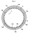
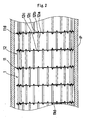
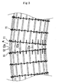
- a plurality of ring-like reinforcing members 11 and a plurality of connecting members 12 for integrally connecting the reinforcing members spaced at a constant interval in the longitudinal direction of the existing conduit P are carried into the existing conduit P through a manhole (M1 and M2 in FIG. 29 ) and etc., to assemble them into a hollow skeleton-like reinforcing body 1 as shown by a sectional view of the existing conduit taken along the radial direction of the existing conduit (hereinafter a sectional view in this direction is referred to as a cross sectional view) in FIG. 1 and a sectional view of the same conduit taken in the longitudinal direction (hereinafter a sectional view in this direction is referred to as a longitudinal sectional view) in FIG.
- the ring-like reinforcing members 11 and the connecting members 12 may be assembled on the ground into a size capable of being carried into the existing conduit P.
- This reinforcing body 1 has an outer shape extending substantially along the inner surface of the existing conduit P, and when the existing conduit P has a circular cross section as with this case, the outer shape of the reinforcing body 1 is configured to be circular. Also, the outer diameter of the reinforcing body 1 is configured to be slightly smaller than the inner diameter of the existing conduit P considering that the existing conduit may have steps or bends.
- the ring-like reinforcing member 11 is, in this embodiment, formed by assembling three arcuate segments 11a, 11b, and 11c by means of connecting members 11d into a ring-like shape that extends as a whole substantially along the inner surface of the existing conduit P.
- the reinforcing member 11 is made of a high rigidity material, for example, steel, and may be surface treated to enhance its durability. Also, the arcuate segments 11a, 11b, 11c may be connected together by placing the ends of them overlapped without using the connecting members 11d.
- each ring-like reinforcing member 11 In the inner periphery of each ring-like reinforcing member 11, there are provided a plurality of concavities for fixing 110 evenly spaced in the circumferential direction into which a fixing bar 2 to be described later is fitted. Also in the outer surface of each ring-like reinforcing member 11, there are provided concavities and convexities 111, which are distributed continuously and uniformly in the circumferential direction, to facilitate the flow of uncured curable infilling, which is to be described later, in the lengthwise direction of the existing conduit when injecting the curable infilling.
- Each concavity for fixing 110 is configured to be wide at substantially central part in the depth direction, and narrower at its opening part.
- each of the ring-like reinforcing member 11 is formed with through holes 112, each of which passes through in the lengthwise direction, as is equally spaced in the circumferential direction.
- the connecting member 12 comprises: a pipe member 12a which is disposed between a pair of ring-like reinforcing members adjacent in the longitudinal direction and acts as a spacer, a bolt 12b with male threads on both ends, and a nut 12c to be screwed in the male thread.
- the bolt 12b is inserted into a pipe member 12a disposed between adjacent ring-like reinforcing members 11 and, in that state, the male thread on each end of the bolt is inserted into a through hole 112 of a ring-like reinforcing member 11 respectively, and then a nut 12c is screwed on each end of the bolt to connect and integrate each ring-like reinforcing member 11 with each other.
- the number of through holes 112 of the ring-like reinforcing member 11 is made larger than the number of the bolts 12b inserted into the connecting members 12, and therefore there remain a plurality of through holes 112 unused on each ring-like reinforcing member 11 after the assembly of the reinforcing body 1.
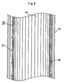
- a plurality of fixing bars 2 are attached in parallel with each other to the inside of the hollow skeleton-like reinforcing body 1 along the lengthwise direction of the existing conduit P.
- Each of the fixing bars 2 is a long member with a uniform cross section, and the length may be as long as the distance between manholes in the existing conduit.
- the fixing bar 2 is mounted to the reinforcing body 1 by fitting the fixing bar 2 into each of the concavities for fixing 110 formed in the inner periphery of the ring-like reinforcing member 11.
- the fixing bar 2 has a cross section of a substantially uniform thickness as shown by a cross sectional view in FIG.
- the fixing bar 2 is attached to the reinforcing body 1 in such a way that the opening part 21 faces the inside of the reinforcing body 1 so that the opening part 21 matches to the opening part of the concavity for fixing 110.
- the fixing bar 2 may be made of a thermoplastic resin, heat-hardening resin, or the like as with the case of the inner face bar 3 to be described below.
- the inner face bars 3 are attached to the inside of the reinforcing body 1 via each fixing bar 2.
- the inner face bar 3 of this example is a plate-like long member extending along the lengthwise direction of the existing conduit P, and may have a length, for example, equal to the distance between manholes in an existing conduit. Also its cross section is in bilateral symmetry as shown by an enlarged view in FIG. 9 , and convexities for fixings 31a, 31b are integrally formed on both edges on one surface of the inner face bar.
- the inner face bar 33 may be made of, for example, a thermoplastic resin including polystyrene resin for sewer pipes and olefin resins, a thermosetting resin including unsaturated polyester resins, or a fiber reinforced plastics such as GFRP and etc., or a metal including a stainless steel.
- the distance between the convexities for fixing 31a, 31b of the inner face bar 3 is equaled to the distance between fixing bars attached in parallel with each other to the inside of the reinforcing body 1, and the inner face bar 3 is inserted into an opening part 21 of a fixing bar 2 respectively in a state that the convexity for fixing 31a of an inner face bar 3 abuts on the convexity for fixing 31b of another inner face bar 3.
- the projecting end part of each convexity for fixing 31a, 31b is spaced wider than the width of the opening part 21 of the fixing bar 2, and therefore the inner face bars 3 are securely held in the reinforcing body 1 via the fixing bars 2.
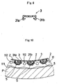
- the inner face bar 3 may be taken up on a reel and then, in that state, introduced inside the reinforcing body 1 in the existing conduit P through a manhole, thereafter being fitted into fixing bars 2. Also, to achieve watertightness between two adjacent inner face bars 3, it is preferable to interpose a sealing material 5 such as a synthetic rubber and water-swelling rubber between the top end surface of each convexity for fixing 31a, 31b of each inner face bar 3 and a fixing bar 2 as shown in an enlarged sectional view of FIG. 10 .
- a sealing material 5 such as a synthetic rubber and water-swelling rubber
- a curable infilling 4 is injected between the existing conduit P and the inner face bar 3, and cured.
- a cement milk a cement material such as a concrete, or a thermosetting resin such as unsaturated polyester resins and epoxy resins may be used, and a suitable one is selected depending on the required performance and cost.
- a grouting structure which is to be described later, is preferable, but other structures such as a framework provided at the end of the existing conduit may be used.
- a hollow skeleton-like reinforcing body 1 is provided inside an existing conduit P, the skeleton body being formed by connecting and integrating a plurality of high rigidity ring-like reinforcing members 11 by means of connecting members 12 along the lengthwise direction of the existing conduit; and there is provided a curable infilling 4 filling up between the inner face bar 3 and the existing conduit P in a state that the inner face bars 3 are fitted to and supported by the reinforcing body 1 via the fixing bar 2.
- This configuration achieves a state in which a pipe of a reinforcing steel structure is built in the existing conduit P, thereby achieving a very high strength of the pipe after repairing.
- curable infilling 4 hardens in a state that it has flown into through holes 112 formed on the ring-like reinforcing member 11, the curable infilling 4 and the reinforcing body 1 are bonded more strongly by an anchor effect thus providing stable strength.
- the inner face bar 3 is a strip-like member which is continuous in the lengthwise direction of the existing conduit P, the inner surface of the repaired conduit will have no seams in the lengthwise direction, and thereby the flow capacity of the conduit will be increased.
- the reinforcing body 1 when the reinforcing body 1 can possibly be moved up upon injecting the curable infilling 4, it is possible to cope with that situation by mounting a space infilling 6 at the top of the reinforcing body 1 as shown in FIG. 12 .
- space infilling 6 may be provided on the sides of the reinforcing body 1. This space infilling 6 provided on the side will make the reinforcing body 1 abut on the existing conduit P thus restricting the deformation of the reinforcing body when subjected to an outer force.
- the space infilling 6 can be secured by utilizing the through holes 112 of the ring-like reinforcing member 11 or in some other methods.
- FIG. 13(A) a cross sectional view and as an enlarged view of the relevant part in FIG. 13(B) .
- the sealing material 5 to provide watertightness between adjacent inner face bars 3 is preferably interposed between the contact surfaces of the inner face bars 3.
- FIG. 14 a cross sectional view to show a case in which the present invention is applied to a horseshoe-shape conduit.
- FIG. 14 almost same configuration as that of the embodiments shown in FIGS. 1 to 11 is utilized, and the shape of the segments forming the ring-like reinforcing member 11 of the reinforcing body 1 is suitably modified to comply with the shape of the special-shape conduit P' to be repaired. Then the segments are connected together with a connecting member 11d similar to that for the above described embodiment to form, as a whole, into a shape extending substantially along the inner surface of the special shape conduit P' to be repaired.
- the present invention can be readily applied.
- the inner face bar used in the present invention may be other than the type used in the above described embodiment, which is a long, planar inner face bar 3 provided in the existing conduit P along its lengthwise direction.
- Other examples may include a tubular inner face bar 3' extending substantially along the inner surface of the existing conduit P' and to be fitted to the reinforcing body 1 as schematically shown in FIG. 15 , or an inner face bar 3" having a suitable width to be fitted spirally into the reinforcing body 1 as shown by a schematic longitudinal cross sectional view in FIG. 16 .
- a tubular inner face bar 3' When a tubular inner face bar 3' is used, the member is deformed into a U-shape to taken up on a reel, and thereafter is introduced into the reinforcing body 1 through a manhole from the ground. In this case, as shown in FIG. 15 , it is preferable to divide the tubular inner face bar 3' into pieces of a suitable length in view of workability.
- the concavities for fixing 110 inside the reinforcing body 1 are, as a matter of course, disposed in a circle or a spiral to fit the convexities for fixing 31' or 31" formed on the inner face bar 3' or 3".
- the position to form the convexity for fixing for the fitting with respect to the concavity for fixing of the reinforcing body or the fitting with respect to the fixing bar is not specifically limited and, as a matter of course, variations are possible.
- convexities for fixing 31a, 31b may be provided on both side edges as shown in FIG. 9 , and alternatively as shown by a cross sectional view of a fitted state in FIG.
- symmetrical convexities for fixing 31a, 31b similar to the above described example are provided on both side edges and, in the middle thereof, a convexity for fixing 31c of a shape formed by combining two foregoing convexities, the middle convexity for fixing 31 c being fitted individually into the concavity for fixing 110 of the fixing bar 2 or the reinforcing body 1.
- a tubular surface bar 7 extending along the inner periphery of the existing conduit P as shown by a cross sectional view in FIG. 18 .
- This surface bar 7 can prevent the curable infilling 4 from leaking out of the existing conduit and also prevent the performance degradation of the curable infilling 4 due to the contact with underground water.
- a fabric sheet or anti-water sheet is used and secured to the inner surface of the existing conduit P by a suitable securing method using a nail or adhesive.
- FIG. 19 is a sectional view to show a state before injecting the curable infilling; the figure explains the structure of an embodiment of the present invention.
- the existing conduit P is shown sectioned by a vertical plane along the lengthwise direction, and the repairing structure is shown by sectioning its upper body by same vertical plane.
- FIG. 20 shows an A-A section of FIG. 19
- FIG. 21 shows an enlarged view of the part B in FIG. 20 respectively.
- a hollow skeleton-like reinforcing body 1 is disposed in the existing conduit P and the inner face bar 3 is secured to the inside of the reinforcing body via the fixing bar 2, thereby forming a tubular repairing material ex tending along the existing conduit P as a whole.
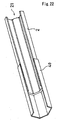
- the fixing bar 2 is a molded part having a uniform cross section of angular C shape similar to that of the concavity for fixing 110 of the above described ring-like reinforcing member 11.
- the fixing bar 2 has, for example, a constant length of 5 m. Attachment of the fixing bars to the reinforcing body is performed by making the opening part shown by numeral 21 in FIG. 22 face inward and, in that state, fitting them into each concavity for fixing 110 of a plurality of ring-like reinforcing members 11 disposed in the lengthwise direction.
- the above described fixing bar 2 having a constant length covers the repairing length with a plurality of members connected together in the lengthwise direction of the existing conduit P. That is, the plurality of the fixing bars 2 are connected together by means of the fixing bar connecting member 40 with their end faces adjoining to each other in the lengthwise direction being abutted against each other, to make the whole length correspond to the repair length of existing conduit P, the whole body being secured to the reinforcing body 1.
- the fixing bar connecting member 40 is a member with an uniform cross section of a angular C shape into which the fixing bar 2 is fitted as shown in FIG. 22 ; its material may be a metal including stainless steel, a thermoplastic resin molding, heat-curable resin (including FRP) molding. Particularly, in the embodiment of the present invention, a material of high rigidity is preferably used.
- a material of high rigidity is preferably used.
- the inner face bars 3 are attached to a plurality of the fixing bars 2 connected to each other with fixing bar connecting members 40 in the lengthwise direction of the existing conduit P and attached to the inside of the reinforcing body 1 evenly spaced in its circumferential direction.
- the inner face bar 3 is, as a perspective view of FIG. 23 shows a state in which its end is inserted into an inner face bar connecting member 50 to be described later, a strip-like body having a bilaterally symmetrical, uniform cross section and a constant length of, for example, about 5 m.
- the inner face bar 3 has a cross sectional shape which is integrally formed with convexities for fixing 31a, 31b projecting to one side from both edges of the strip-like main body.
- the distance between the convexities for fixing 31a, 31b is equaled to the distance between the fixing bars 2 secured in parallel to the inside the reinforcing body 1.
- Adjacent inner face bars 3 are inserted into the opening part 21 of each fixing bar 2 in a state that a convexity for fixing 31a of one inner face bar 3 and a convexity for fixing 31b of the other inner face bar 3 are abutted against each other. In this inserted state, the projection tip part of each convexity for fixing 31a, 31b is spaced more widely than the width of the opening part 21 of the fixing bar 2, and therefore the inner face bars 3 are securely held by the reinforcing body 1 via the fixing bars 2.
- a plurality of inner face bars each of which having a constant length as described above are connected in the lengthwise direction of the existing conduit P to cover the repairing distance. That is, a plurality of inner face bars 3 are connected by means of inner face bar connecting members 50 in a state that their ends adjacent in the lengthwise direction are abutted against each other, into a length corresponding to the repair length of the existing conduit P as a whole. And the whole body is attached to the fixing bars 2 connected by means of fixing bar connecting members 40.
- the inner face bar connecting member 50 has an uniform cross section of a U-shape as shown in FIG. 23 , and is shaped so as to be fitted into the inside of the inner face bar 3.
- the inner face bar connecting member 50 may be composed of a metalworking product including a stainless steel part, a molded product of thermoplastic resin, or a molded product of thermosetting resin (including FRP). In an embodiment of the present invention, a rigid part is preferably used.
- one half-length part of the inner face bar connecting member 50 is fitted to the inside of an end of one inner face bar 3 with the remaining half part being left outside, and to the remaining half part, an end of the other inner face bar 3 is inserted so that ends of the two inner face bars 3 are faced and abutted against each other.
- the abutting part of both ends is preferably configured to be a fully water-proof structure by using an adhesive or sealing material or by integrating them by means of fusion or the like as with the case of the above described fixing bar 2.
- a work environment for an operator is prepared in an existing conduit by a suitable method such as providing a plug in the upstream of the existing conduit P. It is preferable, in view of workability, that the reinforcing body 1 is partially assembled to an extent that the sizes of the arcuate segments 11a, 11b, 11c and the connecting member 12 are within the limit to carry them into the existing conduit P from a manhole and the like.
- the partial reinforcing bodies are formed by connecting three of arcuate segments 11a, 11b, 11c, each of which is a 1/3 part of the circumference, in the lengthwise direction by means of connecting members 12 without connecting them in the circumferential direction. Then the partial reinforcing bodies are carried successively into the existing conduit P and disposed from a reference position such as, for example, an end or a bend of the existing conduit P, to connect them in the circumferential and lengthwise directions obtaining a tubular reinforcing body 1 as a whole.
- fixing bars 2 are fitted into each concavity for fixing 110 inside the reinforcing body 1 respectively. This state is shown by a sectional view in FIG. 24 , and an enlarged view of the part A is shown in FIG. 24 .
- a pair of inner face bars 3 fitted into the fixing bar 2. These fixing bars 2 and the inner face bars are connected by means of the fixing bar connecting members 40 and the inner face bar connecting members 50 respectively by the above described method to form a continuous body in the lengthwise direction.
- a sealing material 5 such as a synthetic rubber and water growth rubber between the fixing bar 2 and the tip part of each convexity for fixing 31a, 31b of the inner face bar 3 which is to be fitted therein. Further, as shown in FIG. 21 , the sealing material 5 may be interposed between the side surfaces of the convexities for fixing 31a, 31b of each inner face bar 3.
- the inner face bar connecting members 50 Upon attaching the inner face bar 3, it is preferable to arrange such that the inner face bar connecting members 50 will not be aligned in the circumferential direction. That is, as shown in FIG. 19 , the connecting positions of the inner face bars 3 by means of the inner face bar connecting members 50 are displaced from each other in the lengthwise direction for circumferentially adjacent pairs.
- the gap even if a gap is produced at the connected portion of the inner face bars 3 when tension is applied on the inner face bar 3 in the lengthwise direction of the existing conduit P due to, for example, an earthquake, the gap will not grow into a continuous one in the lengthwise direction of the existing conduit P, and thus the structure is stabilized.
- the fixing bar connecting members 40 are not aligned in the circumferential direction.
- Such effect is more securely achieved by placing a sealing material 5 between the tips of the convexities for fixing 31a, 31b of the inner face bar 3 and the fixing bar 2, or by adopting a configuration in which abutting ends at the connected portions of the inner face bars 2 the fixing bars 3 are integrated by means of an adhesive or the like. Then, in a state shown in FIGS. 19 and 20 , a curable infilling is injected into between the inner face bar 3 and the existing conduit P and cured to fill in the gap.
- the cross section shape of the fixing bar 2 used in the present invention is not limited to the angular C-shape as shown in the above described embodiment, but any shape may be adopted as long as the outer shape can be fitted into the reinforcing body 1 and the inner shape is such that a pair of inner face bars 3 can be fitted thereinto.
- the shape of the fixing bar connecting member 30 is neither limited to the shape adopted in the above described embodiment, nor limited to be fitted into the outer surface of the fixing bar 2, and it may be attached to the inner surface.
- a H-shape cross section configuration which covers both inner and outer surfaces of the inner face bar 3 may be adopted.
- the shape and size of the convexities for fixing 31a, 31b of the inner face bar 3 are configured to be uniform and continuous in the lengthwise direction, a configuration in which the inner face bar 3 is mounted on only the outer surface of the fixing bar 2 is preferable.
- the fixing bar 2 may not be used in the present invention; instead, the inner face bars 3 may be directly fitted and secured to the reinforcing body 1.
- the cross section shape of the inner face bar 3 is not limited to the shape adopted in the above described embodiments, but any shape can be adopted as long as they can be fitted in a pair into the opening part 21 of the fixing bar 2, or into the concavity for fixing 110 when being directly fitted to the reinforcing body 1.
- the cross section shape of the inner face bar connecting member 50 is limited to a U-shape as with the above described embodiment, nor its configuration is limited to one in which it is attached to the inside (between the convexities for fixing 31a, 31b) of the inner face bar, but configuration in which it is attached to the opposing surfaces may be adopted, and further a configuration of a H-shape cross section which covers both inner and outer surfaces of the inner face bar 3 may be adopted.
- the fixing bars 2 and the inner face bars 3 are attached to the reinforcing body 1 after carrying in the partial reinforcing bodies into the existing conduit P to assemble them into a tubular hollow skeleton form, it is also possible to carry in the partial reinforcing bodies with the fixing bars 2 and the inner face bars 3 being attached thereto in advance.
- the term manhole in the present invention indicates not only one of a specified size but also one of a different size when the manhole is expanded in diameter to cope with the worksite situation or a pit is provided in the middle of the conduit.
- FIG. 26 is a cross sectional view to show the configuration near the end of the repairing material 100 of the embodiment according to the present invention
- FIG. 27 is an enlarged view of the relevant part.
- FIG. 28 is a view in the direction of arrow A in FIG. 26 ; by way of simplification, the hollow diametrically-expansible members 400a located inside are not shown in FIG. 28 .
- This embodiment shows an example in which the present invention is applied to an existing conduit P of a circular cross section; as schematically shown in FIG. 29 , a repairing material 100 is installed in a tubular form inside the existing conduit P between the manholes M1 and M2.
- This repairing material 100 is formed by disposing a plurality of reinforcing bodies 1 made of steel or the like in parallel with each other along the inner surface of the existing conduit P, and connecting each reinforcing body 1 by means of the connecting member 12 in the lengthwise direction of the existing conduit P attaching the inner face bars 3 thereon.
- Each reinforcing body 1 is formed with suitable through holes 112 so that the injected curable infilling 4 can flow in the lengthwise direction.
- tubular member 200 made of a permeable material is fixed by pressure onto the inner surface of one end of the repairing material 100 indicated by E1 in FIG. 29 along the circumferential direction, and the other end of this tubular member 200 is similarly fixed by pressure to the inner surface of the existing conduit P along the circumferential direction at a position of a predetermined distance outwardly away from the end of the repairing material 100 in the lengthwise direction.
- hollow resilient members 300a, 300b are disposed along the inner surface of an end part of the repairing material 100 and the inner surface of the existing conduit P, and both ends of the tubular member 200 are disposed along the inner surface of each hollow resilient member 300a, 300b in the circumferential direction respectively.
- hollow diametrically-expansible members 400a, 400b are disposed and the tubular member 200 is expanded in diameter from inside to be presses against the inner surface of the repairing material 100 or the inner surface of the existing conduit P via the hollow resilient members 300a, 300b, and thereby fitting the tubular member 200 by pressure to these inner surfaces.
- the tubular member 200 is made of canvas composed of cloth such as woven fabric and formed into a tubular shape by sewing; one end of which is matched to the inner perimeter of the repairing material 100 and the other end matched to the inner perimeter of the existing conduit P.
- a canvas material and a sewing method to offer strength to withstand the injection pressure of the grouting material is chosen.
- closed-cell sponge rubber or others is used, and there is no specific limitation on the material for the hollow resilient members 300a, 300b, since they are temporal member to be removed after the injection and curing of the back filler, and rubbers such as CR or urethanes are suitable.
- a Shore hardness of about 25A is preferable since it will provide sufficient flexibility for suitably complying with uneven spots of the inner surfaces of the repairing material 100 and the existing conduit P, and also sufficient rigidity for preventing deformation due to injection pressure of the grouting material by repulsing the compression by the diameter expansion members 400a, 400b.
- These hollow resilient members 300a, 300b is such that a block-like members are bonded at their ends with an adhesive or the like, and its outer shape conforms with the inner surfaces of the existing conduit P and the repairing material 100.
- the actual shape is selected to comply with the cross section shape of the conduit such that when the cross section shape of the existing conduit P is circular, a ring-like shape is selected, and a horseshoe shape for a horseshoe shape conduit.
- the thickness in the radial direction is preferably about 10 mm in view of obtaining suitable compression displacement.
- the diameter and width may be determined so as to comply with each working site.
- the hollow diametrically-expansible members 400a, 400b have the same configuration to each other, in which steel rings 410a, 410b divided into a number of parts, and a plurality of jacks 420a, 420b are used. Referring to FIG. 28 , this configuration will be explained taking the outer hollow diametrically-expansible member 400b for example. Each divided piece 411b forming the steel ring 410b is fitted to adjacent one to be slidable in the circumferential direction, and these pairs are connected to each other with the jacks 420b. The same is true for the inner hollow diametrically-expansible member 400a.
- each diametrically-expansible members 400a, 400b have a configuration in which tow pairs of steel rings 410a, 410a or 410b, 410b are disposed in parallel with each other in the lengthwise direction of the existing conduit P, corresponding divided pieces 411a, 411a or 411b, 411b are fixed to each other by means of a connecting member F such as a bolt.
- each jack 420a, 420b is attached to the connecting members F respectively via engaging members C provided at both ends thereof, and the two steel rings 410a, 410a, or 410b, 410b are expanded in diameter by operating the jacks 420a, 420b.
- each hollow diametrically-expansible member 4001, 400b using 2 steel rings 410a, 410a, or 410b, 410b respectively, it is possible to readily install them at a right angle without making them slanted during the installation in the conduit.
- each hollow diametrically-expansible member 400a, 400b is formed by a set of steel ring 410a, 410b respectively, it is possible to achieve the same effect as that of the present embodiment by installing them exactly at a right angle in the conduit.
- the contours of the hollow diametrically-expansible members 400a, 400b are configured, as with the case of the hollow resilient members 300a, 300b, to conform with the shape of the existing conduit P, for example configured to be ring-like when applying for conduits with a circular cross section as with the present embodiment, and to be a horseshoe shape when applying for a horseshoe shape conduit.
- the hollow diametrically-expansible members 400a, 400b are not limited to the above described configurations, but for example, an inflation bag such as a tire inner tube may used to expand the tubular member 200 in diameter by injecting air into the bag.
- the tubular member 200 is provided with a plurality of injection openings 500 for grouting material.
- These injection openings 500 of grouting material may be composed of any part that can be connected to the tip of the injection hose (not shown) of grouting material, and may be made of either metal or plastics.
- a structure shown in FIG. 27 is used in which the flange 500a is on one end formed with a long sleeve 500b on which a male thread is provided for connecting the hose via a conduit joint, and on the other end with a short sleeve 500d on which a female thread is provided for screwing the nut 500c.
- the tubular member 200 is drilled with a hole, and the tubular member 200 is put between the nut 500c and the flange 500a by screwing the nut 500c onto the short sleeve 500d in a state that the short sleeve 500d of the injection opening 500 for grouting material is inserted into the hole to place the flange 500a along the surface of the tubular member 200. It is preferable to fill an adhesive around the hole of the tubular member 200 to prevent a fray, or to fuse the threads by making a hole with a tong.
- the method for constructing the above described end structure will be described.
- the tubular member 200, the hollow resilient member 300a, 300b, the hollow diametrically-expansible members 400a, 400b, and others for constructing the end structure are carried into the existing conduit P through the manhole M1 shown in FIG. 29 or the like.
- a hollow resilient member 300a is disposed in the inner surface of an end part of the repairing material 100 and, at a position a predetermined distance away therefrom in the lengthwise direction, a hollow resilient member 300b is disposed in the inner surface of the existing conduit P.
- each hollow resilient member 300a, 300b is preferably fixed temporarily with an adhesive tape or the like.
- a tubular member 200 composed of a permeable material is disposed so that its one end slightly protrudes inwardly over the inner hollow resilient member 300a, and the other end protrudes outwardly from the outer hollow resilient member 300b.
- both ends of the tubular member 200 are preferably temporarily secured along the inner periphery of the hollow resilient members 300a, 300b with adhesive tape and the like.
- the tubular member 200 is mounted with a plurality of injection openings 500 for grouting material in advance.
- the inner hollow diametrically-expansible member 400a is assembled inside one end of the tubular member 200, jacks 420a are operated to expand the diameter, and one end of the tubular member 200 is fixed by pressure to the inner surface of the repairing material 100 by making the hollow resilient member 300a deform by compression via the tubular member 200.
- the outer hollow resilient member 400b is assembled inside the other end of the tubular member 200, jacks 420b are operated to expand the diameter, and the other end of the tubular member 200 is fixed by pressure to the inner surface of the existing conduit P by making the hollow resilient member 300b deform by compression via the tubular member 200.
- the other end of the existing conduit P indicated by E2 in FIG. 29 is preferably sealed by an end structure which is equivalent to the above described end structure except providing no injection opening 500 for grouting material, and in a state that the other end E2 is sealed, injection of the grouting material is performed by connecting a hose to each injection opening 500 for grouting material.
- the end part of the repairing material 100 make both ends of the tubular member 200 securely be fixed by pressure to the inner surface of the existing conduit P and the inner surface of the repairing material 100 by the diameter expansion of the hollow diametrically-expansible members 400a, 400b, the injection pressure of the grouting material can be significantly raised compared to the case in which sealing material such as mortar is used to seal both ends of the conduit, thereby increasing the work efficiently.
- each hollow diametrically-expansible member 400a, 400b, each hollow resilient member 300a, 300b, and the tubular member 200 are removed.
- a mold release agent on the part to be in contact with the grouting material in advance so that the grouting material is easily removed without being integrated with the other part.
- an example is shown in which each hollow resilient member 300a, 300b is disposed outside the tubular member 200, and the injection opening 500 for grouting material is provided on the tubular member 200.
- each hollow resilient member 300a, 300b may be disposed inside the tubular member 200, and the injection opening 500 for grouting material may be provided in the repairing material 100.
- FIGS. 30 and 31 Such example is shown by a sectional view in FIGS. 30 and 31 .
- FIG. 30 shows that in the end part of the tubular member 200 to be fixed by pressure to the inner surface of the existing conduit P, a hollow resilient member 300b is disposed inside the tubular member 200, and further inside of the hollow resilient member, a hollow diametrically-expansible member 400b is disposed. Then by expanding the hollow diameter expanding member 400b in diameter, the tubular member 200 is fixed by pressure to the inner surface of the existing conduit P. Moreover, FIG.
- a hollow resilient member 300a is disposed on the outer surface side of the repairing material as with the previous example, and a hollow diametrically-expansible member 400a is disposed on the inner surface side of the tubular member 200.
- hollow resilient members 300a, 300b are disposed on the inner face side of the tubular member 200, and both ends of the tubular member 200 are fixed by pressure to the inner surface of the repairing material 100 or the inner surface of the existing conduit P by means of the hollow diametrically-expansible members 400a, 400b disposed inside the hollow resilient members via the follow resilient members.
- the injection opening 500 for grouting material is provided in the repairing material 100 near the end part of the tubular member 2.
- the structure for the mounting of the injection opening 500 for grouting material onto the repairing material 100 may be an equivalent structure for the mounting to the tubular member 200, or may be a structure in which the inner face bar 3 itself is formed with a female thread by use of a tap, and a pipe on which a male thread is formed is screwed into the female thread.
- hollow resilient members 300a, 300b are interposed in the portion where both ends of the tubular member 200 are fixed by pressure to the inner surface of the end part of the repairing material 100 and the inner surface of the existing conduit P so that sealing is easily ensured by absorbing the irregularities in the inner surface of the repairing material 100 and the inner surface of the existing conduit P.
- hollow resilient members 300a, 300b are not always needed and whether or not to use them may be determined depending the surface irregularity conditions of each inner surface.
- a reinforcing body of a hollow skeleton structure is assembled in an existing conduit and inner face bars are attached to the reinforcing body using a method such as fitting, and in that state, a curable infilling is charged between the inner surface of the existing conduit and the inner face bar, and this configuration makes it possible to suitably change the shape and size of the reinforcing members constituting the reinforcing body to construct a reinforcing body having a sufficient strength depending on the degree of the deterioration of the conduit. Therefore, even when repairing a severely degraded conduit that has lost its strength or a large diameter conduit such as a tunnel, it is possible to provide the conduit with enough strength.
- the strength of the reinforcing body can be raised sufficiently high, it is possible to select a material with a good fluidity and of a low price for the curable infilling, thus achieving good workability and low cost. It is also possible to cope with the case in which there is a step or a bend in the middle of an existing conduit, and moreover it is possible to construct a reinforcing body having a shape conforming to special-shape conduits such as a horseshoe-shape conduit and a box culvert conduit. Thus repair work can be performed under good workability.
- the inner face bar made of a thermoplastic molded part, it can be easily deformed to be fitted into the reinforcing body in a step or bend part of a conduit, and in a special shape conduit, thereby achieving a smooth inner surface of the conduit after repair.
- the inner face bars are fitted into the reinforcing thus being supported thereby, external water pressure will not act only on the inner face bar, and therefore the inner face bar is not likely to deform.
- the inner face can withstand the injection pressure during the injection of curable infilling thereby eliminating the need of conventional counter measures such as preparing a supporting, and thus, the construction time will be reduced.
- the repairing material by exploiting a long body having a length of, for example, a manhole-to-manhole distance for the inner face bar, it is possible to provide the repairing material with a seamless inner face (surface) in the down flow direction, thereby substantially improving the flow capacity compared to the case in which the inner face bar is disposed in a spiral form.
- a plurality of inner face bars are attached to the reinforcing body by connecting them in the lengthwise direction by means of inner face bar connecting members, and at connected portions of the inner face bars, end faces of adjacent inner face bars are abutted against each other and these members are connected by means of inner face bar connecting member disposed over the adjacent inner face bars.
- a similar arrangement may be made for the fixing bar such that a plurality of fixing bars are connected together in the lengthwise direction of the existing conduit by means of fixing bar connecting members and then attached onto the reinforcing body, and at the connected portion of the fixing bars, end parts of adjacent fixing bars are abutted against each other to connect them together by means of the fixing bar connecting members disposed over the adjacent fixing bars.
- the strength of the connected portion of the fixing bars is increased as described above, and it is made possible to achieve performance comparable to the case in which a single long fixing bar is used over the whole repairing length of an existing conduit.
- this arrangement can solve the problems of manufacturing and transportation due to upsizing of the inner face bar, and can achieve improvement of workability in the field owing to the ease of handling.
- both ends of a tubular member made of a permeable material are fixed by pressure from inside onto the inner surface of the end part of the repairing material and inner surface of the existing conduit at a position a predetermined distance away therefrom by means of an hollow diametrically-expansible member, and an injection opening for grouting material is provided in the tubular member or the repairing material in the vicinity thereof.
- the injection operation of grouting material can be started immediately without waiting for the hardening of the sealing material, the injection end of the grouting material can be sealed securely without being affected by the conditions of the inner surface of the existing conduit such as running water. And also the injection pressure of the grouting material can be raised to a high level than conventional level, thus substantially improving the workability.
- the tubular member for sealing is made of a permeable material, air and excessive water can be discharged to outside during the injection of the grouting material, thus improving the quality of the grouting material after curing.
- the end structure of the present invention on one end and constructing another structure, which is equal to the end structure of the present invention excepting the injection opening for grouting material, on the other end, it is made possible to ensure the sealing of both ends of the injection space of the grouting material and to discharge standing air and excessive water in the whole length of the injection space or water intruding from the inside and outside of the conduit, thereby substantially improving the quality of the injected grouting material.
Landscapes
- Engineering & Computer Science (AREA)
- Structural Engineering (AREA)
- General Engineering & Computer Science (AREA)
- Mining & Mineral Resources (AREA)
- Architecture (AREA)
- Civil Engineering (AREA)
- Mechanical Engineering (AREA)
- Life Sciences & Earth Sciences (AREA)
- General Life Sciences & Earth Sciences (AREA)
- Geochemistry & Mineralogy (AREA)
- Geology (AREA)
- Pipe Accessories (AREA)
- Sewage (AREA)
Claims (25)
- Verfahren zur Reparatur eines bestehenden Kanals (P), umfassend die Schritte;- Vorbereiten einer Vielzahl von Verstärkungselementen (11), die in den bestehenden Kanal (P) hineingetragen werden können;- Aufbauen der Verstärkungselemente (11) zu einem hohlen, skelettartigen Verstärkungskörper (1), der sich im Wesentlichen entlang der Innenfläche des bestehenden Kanals (P) erstreckt,
wobei der Aufbauschritt umfasst;- Verwenden eines ringartigen Verstärkungselementes (11), welches sich im Wesentlichen entlang der Innenfläche des bestehenden Kanals (P) erstreckt;- Anordnen einer Vielzahl der ringartigen Verstärkungselemente (11) in einem vorbestimmten Intervall in der Längsrichtung des bestehenden Kanals (P); und- Integrieren der Verstärkungselemente (11) mittels einer Vielzahl von Verbindungselementen (12) in der Längsrichtung;- Befestigen einer Vielzahl von Innenflächenstangen (3) an der Innenseite des Verstärkungskörpers (1), um diese zu einer Kanalform zusammenzubauen, die sich entlang der Länge des bestehenden Kanals (P) erstreckt;
und anschließend;- Einspritzen eines härtbaren Füllmaterials (4) in einen Spalt zwischen den Innenflächenstangen (3) und der Innenfläche des bestehenden Kanals (P). - Verfahren zur Reparatur eines bestehenden Kanals (P) nach Anspruch 1, dadurch gekennzeichnet, dass eine Vielzahl von Befestigungsstangen (2) an der Innenseite des Verstärkungskörpers (1) angebracht werden und dass die Innenflächenstangen (3) in die Befestigungsstangen (2) eingesetzt werden.
- Verfahren zur Reparatur eines bestehenden Kanals (P) nach Anspruch 2, dadurch gekennzeichnet, dass ein langes Element, das in der Längsrichtung des bestehenden Kanals (P) nicht unterbrochen ist, als Befestigungsstange (2) verwendet wird.
- Verfahren zur Reparatur eines bestehenden Kanals (P) nach Anspruch 1, 2 oder 3, dadurch gekennzeichnet, dass ein langer Körper, welcher in der Längsrichtung des bestehenden Kanals (P) nicht unterbrochen ist, als Innenflächenstange (3) verwendet wird.
- Verfahren zur Reparatur eines bestehenden Kanals (P) nach Anspruch 1, 2, 3 oder 4, dadurch gekennzeichnet, dass der Schritt des Aufbauens des Verstärkungskörpers (1) umfasst:Aufbauen partieller Verstärkungskörper aus entlang ihres Umfangs unterteilten, ringartigen Verstärkungselementen (11) und aus Verbindungselementen (12) außerhalb des bestehenden Kanals (P) und anschließendes Hineintragen der partiellen Verstärkungskörper in den bestehenden Kanal (P) zum Zwecke der Montage.
- Verfahren zur Reparatur eines bestehenden Kanals (P) nach Anspruch 1, 2, 3, 4 oder 5, dadurch gekennzeichnet, dass ein Raum-Füllelement (6) am Umfang des Verstärkungskörpers (1) vorgesehen wird, um den Spalt zwischen dem Innenumfang des bestehenden Kanals (P) und dem Verstärkungskörper (1) mittels des Raum-Füllelementes (6) zu vermindern oder zu beseitigen.
- Verfahren zur Reparatur eines bestehenden Kanals (P) nach Anspruch 1, 2, 3, 4, 5 oder 6, dadurch gekennzeichnet, dass der Aufbau des Verstärkungskörpers (1) erfolgt, nachdem eine Stange mit rohrförmiger Oberfläche (7), welche sich entlang der Innenfläche des bestehenden Kanals (P) erstreckt, an der Innenseite des existierenden Kanals (P) angeordnet worden ist.
- Verfahren zur Reparatur eines bestehenden Kanals (P) nach Anspruch 1, 2, 3, 4, 5, 6 oder 7, dadurch gekennzeichnet, dass das Einspritzen des härtbaren Füllmaterials (4) durch eine Einspritzöffnung für Vergussmaterial hindurch erfolgt, welche in einem in der Nähe eines Endes des Reparaturmaterials angeordneten, durchlässigen Material vorgesehen wird.
- Reparaturmaterial zur Verwendung bei der Reparatur eines bestehenden Kanals (P), umfassend:- einen Verstärkungskörper (1) mit einer hohlen Skelettstruktur, welcher sich im Wesentlichen entlang der Innenfläche des bestehenden Kanals (P) erstreckt, wobei der Verstärkungskörper (1) aus einer Vielzahl von entlang ihres Umfangs unterteilten, ringartigen Verstärkungselementen (11) aufgebaut wird, von denen jedes eine Vielzahl von Befestigungseinrichtungen (110) in seiner Innenseite aufweist, und wobei der Verstärkungskörper (1) eine Vielzahl von ringartigen Verstärkungselementen (11), die in einem vorbestimmten Intervall in der Längsrichtung des bestehenden Kanals (P) angebracht werden, sowie eine Vielzahl von Verbindungselementen (12) zum Verbinden und Integrieren der ringartigen Verstärkungselemente (11) miteinander umfasst: und- eine Vielzahl von Innenflächenstangen (3), von denen jede eine glatte Fläche aufweist und die in die Befestigungseinrichtungen (110) der Verstärkungselemente (11) eingesetzt werden, um die Innenfläche des Kanals zu bilden.
- Reparaturmaterial zur Reparatur eines bestehenden Kanals (P), umfassend:- einen Verstärkungskörper (1) mit einer hohlen Skelettstruktur, welcher sich im Wesentlichen entlang der Innenfläche des bestehenden Kanals (P) erstreckt, wobei der Verstärkungskörper (1) aus einer Vielzahl von entlang ihres Umfangs unterteilten, ringartigen Verstärkungselementen (11) aufgebaut wird, von denen jedes eine Vielzahl von Befestigungseinrichtungen (110) in seiner Innenseite aufweist, und wobei der Verstärkungskörper (1) eine Vielzahl von ringartigen Verstärkungselementen (11), die in einem vorbestimmten Intervall in der Längsrichtung des bestehenden Kanals (P) angeordnet werden, sowie eine Vielzahl von Verbindungselementen (12) zum verbinden und Integrieren der ringartigen Verstärkungselemente (11) miteinander umfasst;- eine Vielzahl von Befestigungsstangen (2), von denen jede an seiner Außenseite mit einem ersten Befestigungsteil, welcher in die Befestigungseinrichtung (110) passt, und an seiner Innenseite mit einem zweiten Befestigungsteil ausgebildet ist; und- eine Vielzahl von Innenflächenstangen (3), von denen jede eine glatte Innenfläche aufweist und entweder in ihrer Außenfläche oder ihrem Endteil mit einer Befestigungseinrichtung (31a, 31b) ausgebildet ist, die in den zweiten Befestigungsteil eingesetzt wird.
- Reparaturmaterial zur Reparatur eines bestehenden Kanals (P) nach Anspruch 10, dadurch gekennzeichnet, dass jede der Befestigungsstangen (2) ein langes Element ist, das in Längsrichtung des bestehenden Kanals (P) ununterbrochen ist.
- Reparaturmaterial zur Reparatur eines bestehenden Kanals (P) nach Anspruch 9, 10 oder 11, dadurch gekennzeichnet, dass jede der Innenflächenstangen (3) ein langer Körper ist, der in Längsrichtung des bestehenden. Kanals (P) ununterbrochen ist.
- Reparaturmaterial zur Reparatur eines bestehenden Kanals (P) nach Anspruch 9, 10, 11 oder 12, dadurch gekennzeichnet, dass der Verstärkungskörper (1) in seinem Außenumfang mit einer konkaven Vertiefung und einer konvexen Erhöhung (111) ausgebildet ist, um einen nutähnlichen Raum zu bilden, der wenigstens in der Längsrichtung des bestehenden Kanals (P) ununterbrochen ist.
- Reparaturmaterial zur Reparatur eines bestehenden Kanals (P) nach Anspruch 9, 10, 11, 12 oder 13 dadurch gekennzeichnet, dass der verstärkungskörper (1) mit einem durchgehenden Loch (112) ausgebildet ist, welches in Längsrichtung des bestehenden Kanals (P) verläuft.
- Reparaturmaterial zur Reparatur eines bestehenden Kanals (P) nach Anspruch 9, 10, 11, 12, 13 oder 14, dadurch gekennzeichnet, dass der Verstärkungskörper (1) ein Raum-Füllelement (6) aufweist, welches am Außenumfang des Verstärkungskörpers (1) angebracht werden kann und mit welchem ein Spalt zwischen dem Verstärkungskörper (1) und der Innenfläche des bestehenden Kanals (P) vermindert oder eliminiert werden kann.
- Struktur für die Reparatur eines bestehenden Kanals (P), bei welcher- ein Reparaturmaterial nach einem der vorangehenden Ansprüche in dem bestehenden Kanal (P) angeordnet wird, und bei welcher- ein härtbares Füllmaterial (4) vorgesehen wird, um einen Spalt zwischen den Innenflächenstangen (3) und der Innenfläche des bestehenden Kanals (P) zu füllen.
- Struktur für die Reparatur eines bestehenden Kanals (P) nach Anspruch 16, dadurch gekennzeichnet, dass der Verstärkungskörper (1) mit einem durchgehenden Loch (112) ausgebildet ist, welches in Längsrichtung des bestehenden Kanals (P) verläuft, und das Loch (112) mit dem härtbaren Füllmaterial (4) ausgefüllt wird.
- Struktur für die Reparatur eines bestehenden Kanals (P) nach Anspruch 16 oder 17, dadurch gekennzeichnet, dass eine Stange mit rohrförmiger Fläche (7), welche sich entlang der Innenfläche des bestehenden Kanals (P) erstreckt, zwischen dem Verstärkungskörper (1) und der Innenfläche des bestehenden Kanals (P) angeordnet und ein härtbares Füllmaterial (4) vorgesehen wird, welches den Spalt zwischen der Stange (7) und der Innenflächenstange (3) ausfüllt.
- Struktur für die Reparatur eines bestehenden Kanals (P) nach Anspruch 16, bei welcher- die Vielzahl von Innenflächenstangen (3) nacheinander entlang der Längsrichtung beziehungsweise der Umfangsrichtung an der Innenseite des Verstärkungskörpers (1) angebracht wird, um zu einer Kanalform zusammengebaut zu werden, wobei- ein Paar aus Innenflächenstangen (3), welche in der Längsrichtung des bestehenden Kanals (P) benachbart sind, mittels eines Verbindungselementes (50) für Innenflächenstangen untereinander verbunden wird, welches so angeordnet wird, dass es sich, in einem Zustand, in dem die Endflächen der Innenflächenstangen aneinanderstoßen, über beide Innenflächenstangen (3) erstreckt.
- Struktur für die Reparatur eines bestehenden Kanals (P) nach Anspruch 19, dadurch gekennzeichnet, dass eine Vielzahl von Befestigungsstangen (2) nacheinander entlang der Längsrichtung beziehungsweise der Umfangsrichtung an der Innenseite des Verstärkungskörpers (1) angebracht wird, und jede dieser Innenflächenstangen (3) mittels jeder der Befestigungsstangen (2) an dem Verstärkungskörper (1) befestigt wird und dass ein Paar aus Befestigungsstangen (2), die in der Längsrichtung des bestehenden Kanals (P) benachbart sind, untereinander verbunden wird, wobei die Endflächen jedes Elementes mittels eines Verbindungselementes (40) für Befestigungsstangen, welches so angeordnet ist, dass es sich über beide Befestigungsstangen (2) erstreckt, aneinanderstoßend verbunden werden.
- Struktur für die Reparatur eines bestehenden Kanals (P) nach Anspruch 19 oder 20, dadurch gekennzeichnet, dass die Verbindungselemente (50) für Innenflächenstangen zur Verbindung von zwei Innenflächenstangen (3), welche in Längsrichtung einander benachbart sind, so angeordnet werden, dass zwei in Umfangsrichtung benachbarte Verbindungselemente (50) in der Längsrichtung des bestehenden Kanals (P) zueinander versetzt angeordnet sind.
- Struktur für die Reparatur eines bestehenden Kanals (P) nach Anspruch 19, 20 oder 21, dadurch gekennzeichnet, dass die Verbindungselemente (40) für Befestigungsstangen zur Verbindung von zwei Befestigungsstangen (2), welche in der Längsrichtung des bestehenden Kanals (P) einander benachbart sind, so angeordnet werden, dass zwei in Umfangsrichtung benachbarte Verbindungselemente (40) in Längsrichtung des bestehenden Kanals (P) zueinander versetzt angeordnet sind.
- Struktur für die Reparatur eines bestehenden Kanals (P) nach Anspruch 19, 20, 21 oder 22, dadurch gekennzeichnet, dass die Verbindungselemente (50) für Innenflächestangen und die Verbindungselemente (40) für Befestigungsstangen zueinander versetzt angeordnet sind.
- Struktur für die Reparatur eines bestehenden Kanals (P) nach Anspruch 19, 20, 21, 22 oder 23, dadurch gekennzeichnet, dass ein Paar Endflächen der Innenflächenstangen (3) und/oder der Befestigungsstangen (2), welche in der Längsrichtung des bestehenden Kanals (P) benachbart sind, integral miteinander verbunden sind.
- Struktur für die Reparatur eines bestehenden Kanals (P) nach Anspruch 19, 20, 21, 22, 23 oder 24, dadurch gekennzeichnet, dass ein Dichtungsmaterial zwischen der Befestigungsstange (2) und der Innenflächenstange (3) angeordnet wird.
Applications Claiming Priority (7)
| Application Number | Priority Date | Filing Date | Title |
|---|---|---|---|
| JP2000132258 | 2000-05-01 | ||
| JP2000132258A JP4261733B2 (ja) | 2000-05-01 | 2000-05-01 | 既設管路の補修方法およびそれに用いる補修材並びに管路 |
| JP2001045361A JP4305803B2 (ja) | 2001-02-21 | 2001-02-21 | 管路用内張り材端部の裏込め用構造 |
| JP2001045361 | 2001-02-21 | ||
| JP2001108940A JP4390123B2 (ja) | 2001-04-06 | 2001-04-06 | 管路の内張り構造 |
| JP2001108940 | 2001-04-06 | ||
| PCT/JP2001/003760 WO2001084037A1 (en) | 2000-05-01 | 2001-05-01 | Duct repairing material, repairing structure, and repairing method |
Publications (3)
| Publication Number | Publication Date |
|---|---|
| EP1279882A1 EP1279882A1 (de) | 2003-01-29 |
| EP1279882A4 EP1279882A4 (de) | 2006-03-08 |
| EP1279882B1 true EP1279882B1 (de) | 2013-03-06 |
Family
ID=27343294
Family Applications (1)
| Application Number | Title | Priority Date | Filing Date |
|---|---|---|---|
| EP01926085A Expired - Lifetime EP1279882B1 (de) | 2000-05-01 | 2001-05-01 | Material struktur und verfahren zur reparatur von kanälen |
Country Status (5)
| Country | Link |
|---|---|
| US (1) | US6796334B2 (de) |
| EP (1) | EP1279882B1 (de) |
| CA (1) | CA2407297C (de) |
| TW (1) | TW490386B (de) |
| WO (1) | WO2001084037A1 (de) |
Families Citing this family (31)
| Publication number | Priority date | Publication date | Assignee | Title |
|---|---|---|---|---|
| BR0211516B1 (pt) * | 2001-09-15 | 2012-02-07 | elemento e módulo de flutuação e método de fabricação de um elemento de flutuação. | |
| JP2004052485A (ja) * | 2002-07-24 | 2004-02-19 | Shonan Plastic Mfg Co Ltd | 管路補修工法 |
| JP2005264635A (ja) * | 2004-03-22 | 2005-09-29 | Shonan Plastic Mfg Co Ltd | 更生管用セグメント部材 |
| JP4482373B2 (ja) * | 2004-05-14 | 2010-06-16 | 株式会社湘南合成樹脂製作所 | 既設管更生用セグメント部材及びそのセグメント部材を用いた更生管 |
| US7137757B1 (en) | 2005-05-05 | 2006-11-21 | Cosban William C | Method and device for repairing or reinforcing an underground pipe |
| JP4888940B2 (ja) * | 2005-07-13 | 2012-02-29 | 芦森工業株式会社 | 管路の補修構造 |
| US20080075538A1 (en) * | 2006-09-27 | 2008-03-27 | Crane Robert F | Method and apparatus for repairing underground pipes |
| WO2008075406A1 (ja) * | 2006-12-19 | 2008-06-26 | Ashimori Industry Co., Ltd. | 管路の補修構造 |
| FR2943758B1 (fr) * | 2009-03-24 | 2011-03-25 | Technip France | Manchon de protection pour conduite flexible |
| JP5457130B2 (ja) * | 2009-06-03 | 2014-04-02 | 株式会社湘南合成樹脂製作所 | 既設管の更生工法 |
| DE102009057521B4 (de) * | 2009-12-10 | 2011-07-21 | Bochumer Eisenhütte Heintzmann GmbH & Co. KG, 44793 | Tübbing-Ausbau mit integriertem Nachgiebigkeitselement |
| JP6116848B2 (ja) * | 2012-10-04 | 2017-04-19 | 株式会社湘南合成樹脂製作所 | 更生管用セグメントおよび管更生工法 |
| EP2495394A1 (de) * | 2011-03-02 | 2012-09-05 | Silvino Pompeu Santos | Tunnel aus dehnbarem Doppelrohr |
| JP5794845B2 (ja) * | 2011-07-08 | 2015-10-14 | 株式会社湘南合成樹脂製作所 | 更生管及び該更生管を用いた管更生工法 |
| WO2014051041A1 (ja) * | 2012-09-28 | 2014-04-03 | タキロンエンジニアリング株式会社 | 管の内層構造及びそれに使用する連結部材 |
| JP6017254B2 (ja) * | 2012-10-10 | 2016-10-26 | 株式会社湘南合成樹脂製作所 | 更生管用セグメントおよび管更生工法 |
| JP6497957B2 (ja) * | 2015-02-12 | 2019-04-10 | 株式会社湘南合成樹脂製作所 | 更生管の位置調整用スペーサ |
| US10578240B2 (en) | 2016-02-01 | 2020-03-03 | Recyca-Pipe Of America L.L.C. | Expandable pipe including a liner for restoring a conduit |
| EP3521556A1 (de) * | 2018-01-31 | 2019-08-07 | ICW Ingenieur Consult Würzburg Peter Hofstetter | Multifunktionsrahmen im tunnelbau |
| US11131189B2 (en) * | 2018-11-29 | 2021-09-28 | Fci Holdings Delaware, Inc. | Underground support |
| KR102088196B1 (ko) * | 2019-07-24 | 2020-03-12 | 주식회사 씨스 이엔지 | 갱생관용 세그먼트의 연결 방법 및 연결구 |
| US11242750B2 (en) | 2019-11-25 | 2022-02-08 | Fci Holdings Delaware, Inc. | Adjustable lattice girder |
| CN112186665B (zh) * | 2020-09-08 | 2022-01-04 | 成得建设集团有限公司 | 一种气触式自凝结修复的电力波纹管 |
| CN112253168B (zh) * | 2020-10-28 | 2022-04-22 | 中交天和机械设备制造有限公司 | 一种盾构机管片自动化拼装方法及装置 |
| CN112392504A (zh) * | 2020-11-17 | 2021-02-23 | 同济大学 | 一种隧道用自防水波形钢板衬砌结构 |
| JP7497108B2 (ja) * | 2020-11-24 | 2024-06-10 | 芦森工業株式会社 | 剥離防止部材及びこれを備えた管路の内張構造 |
| CN113288381B (zh) * | 2021-05-31 | 2022-08-26 | 河北省胸科医院 | 一种组合式骨折外固定架及其使用方法 |
| CN114165269B (zh) * | 2022-02-14 | 2022-06-17 | 山东建筑大学 | 基于钢混组合支架及喷碹的复合支护系统及其施工工艺 |
| GB2617615B (en) * | 2022-04-14 | 2024-04-03 | Colin Eddie Consulting Ltd | Tunnel lining method and apparatus |
| CN115711155A (zh) * | 2022-12-01 | 2023-02-24 | 北京科技大学 | 一种嵌套式破损充填钻孔修复方法 |
| PL446621A1 (pl) * | 2023-10-31 | 2025-05-05 | Poznańskie Przedsiębiorstwo Robót I Usług Specjalistycznych Remkan Spółka Z Ograniczoną Odpowiedzialnością | Moduł systemu do remontów kanałów przełazowych i sposób prowadzenia remontów kanałów przełazowych |
Family Cites Families (30)
| Publication number | Priority date | Publication date | Assignee | Title |
|---|---|---|---|---|
| US780789A (en) * | 1904-05-26 | 1905-01-24 | Charles T Baum Gardner | Pipe. |
| US1013302A (en) * | 1910-08-10 | 1912-01-02 | Vladimir V Messer | Reinforced-concrete pipe. |
| US1167159A (en) * | 1911-07-19 | 1916-01-04 | William C Flannery | Construction of concrete sewers, aqueducts, &c. |
| US1177311A (en) * | 1913-09-03 | 1916-03-28 | William C Flannery | Tile and fastener for sewers, aqueducts, or like conduits. |
| US1843334A (en) * | 1930-03-19 | 1932-02-02 | Charles A Mcgrath | Adjustable rack for placing reenforcing steel |
| US1880599A (en) * | 1931-01-17 | 1932-10-04 | Bozidar J Ukropina | Concrete pipe joint |
| FR1123740A (fr) * | 1955-03-16 | 1956-09-26 | Porte Et Gardin Soc | Soutènement par palplanches-queues |
| GB1143012A (en) * | 1966-04-26 | 1969-02-19 | Patricia Lorna Kosogorin | Tunnelling method and apparatus |
| US3751929A (en) * | 1969-02-12 | 1973-08-14 | Pfeiffer H | Method of supporting exposed ground or rock |
| CH525354A (de) * | 1970-04-04 | 1972-07-15 | Glatz Horst | Plattenförmiges Bauelement für Betonbauten |
| US3957087A (en) * | 1974-07-03 | 1976-05-18 | Johnston Henry M | Pin and truss cylinder construction |
| ES441608A1 (es) * | 1975-10-08 | 1976-02-16 | Arana Sagasta | Perfeccionamientos introducidos en los sistemas de entiba- cion de excavaciones. |
| IT1188780B (it) * | 1979-03-27 | 1988-01-28 | Pirelli Furlanis | Rivestimento impermeabilizzante per contenitori di liquidi |
| US4467995A (en) * | 1979-07-11 | 1984-08-28 | Tolliver Wilbur E | Spacer bar and related method for concrete pipe manufacture |
| GB2094860B (en) * | 1981-03-14 | 1985-01-23 | Dunlop Ltd | Lining of tubular structures |
| JPS6314997A (ja) * | 1986-07-08 | 1988-01-22 | 山本 稔 | トンネル構築方法 |
| JPS6332096A (ja) * | 1986-07-25 | 1988-02-10 | 鉄建建設株式会社 | シ−ルドトンネルの覆工方法 |
| JPS6388388A (ja) | 1986-09-30 | 1988-04-19 | 東京都下水道サ−ビス株式会社 | ライニング管の裏込め注入方法及びその浮上防止マツト |
| JPS63194098A (ja) * | 1987-02-06 | 1988-08-11 | 鉄建建設株式会社 | シ−ルドトンネルの覆工方法 |
| JPS63268832A (ja) | 1987-04-27 | 1988-11-07 | テイヒュー株式会社 | コンクリ−ト管とその製造方法 |
| JPH06105111B2 (ja) * | 1989-01-25 | 1994-12-21 | 積水化学工業株式会社 | 既設管内埋設管 |
| US5186217A (en) * | 1989-10-21 | 1993-02-16 | Flachglas Consult Gmbh | Fluid-impervious structure and method of making same |
| JP2742986B2 (ja) | 1995-04-07 | 1998-04-22 | 株式会社大阪防水建設社 | 管の内面ライニング工法 |
| US5934334A (en) * | 1996-01-18 | 1999-08-10 | Ford Meter Box Company, Inc. | Casing spacers |
| JP3694129B2 (ja) | 1996-12-09 | 2005-09-14 | 積水化学工業株式会社 | 螺旋管用補強材と、それを用いた螺旋管および既設管のライニング方法 |
| US5927346A (en) * | 1997-01-21 | 1999-07-27 | Majnaric Technologies, Inc. | Concrete pipes and methods for the manufacture thereof |
| US5928447A (en) * | 1997-04-03 | 1999-07-27 | Gianfrancisco; Thomas | Conduit repair and interior reconstruction |
| CA2297456C (en) * | 1999-03-03 | 2009-06-30 | Michael P. Mcnally | Method and apparatus for feeding a tunnel roof support system from the roof shield of a tbm |
| JP2003286742A (ja) * | 2002-01-23 | 2003-10-10 | Shonan Plastic Mfg Co Ltd | 流路施設修復用ブロック体及び流路施設修復工法 |
| JP2004052485A (ja) * | 2002-07-24 | 2004-02-19 | Shonan Plastic Mfg Co Ltd | 管路補修工法 |
-
2001
- 2001-04-30 TW TW090110354A patent/TW490386B/zh not_active IP Right Cessation
- 2001-05-01 WO PCT/JP2001/003760 patent/WO2001084037A1/ja not_active Ceased
- 2001-05-01 US US10/258,991 patent/US6796334B2/en not_active Expired - Lifetime
- 2001-05-01 CA CA002407297A patent/CA2407297C/en not_active Expired - Lifetime
- 2001-05-01 EP EP01926085A patent/EP1279882B1/de not_active Expired - Lifetime
Also Published As
| Publication number | Publication date |
|---|---|
| WO2001084037A1 (en) | 2001-11-08 |
| CA2407297C (en) | 2007-08-21 |
| EP1279882A4 (de) | 2006-03-08 |
| US20030116210A1 (en) | 2003-06-26 |
| TW490386B (en) | 2002-06-11 |
| US6796334B2 (en) | 2004-09-28 |
| CA2407297A1 (en) | 2001-11-08 |
| EP1279882A1 (de) | 2003-01-29 |
Similar Documents
| Publication | Publication Date | Title |
|---|---|---|
| CA2407297C (en) | Duct repairing material, repairing structure, and repairing method | |
| US7056064B2 (en) | Block unit for repairing flow passage facilities and method of repairing flow passage facilities | |
| JP4261733B2 (ja) | 既設管路の補修方法およびそれに用いる補修材並びに管路 | |
| EP1384938A1 (de) | Verfahren zur Sanierung von Strömungskanäle | |
| JP2003314197A (ja) | 管渠の補修方法、及び管渠内補修部構造 | |
| JP4864067B2 (ja) | 既設管路の補修方法およびそれに用いる補修材並びに管路 | |
| KR101732669B1 (ko) | 보강부재, 보강부재를 이용하여 보강된 콘크리트 관로 및 보강부재를 이용한 콘크리트 관로 보수보강공법 | |
| JP2003148091A (ja) | 既設トンネル覆工の補強構造とその施工方法 | |
| EP0925466B1 (de) | Struktur und verfahren zum auskleiden von rohren | |
| KR100836512B1 (ko) | 관로의 보수재, 보수 구조 및 그 보수 방법 | |
| JP2005290846A (ja) | 人孔内周面の更生工法 | |
| JPH04306398A (ja) | コンクリート壁面の補修方法 | |
| JP7654218B2 (ja) | 水路補修方法 | |
| AU2003221369C1 (en) | Block unit for repairing flow passage facilities and method of repairing flow passage facilities | |
| JP2008088715A (ja) | コンクリート構造物の再構築方法、コンクリート構造物の製造方法、及び、これらの工法に用いることができる防食部材 | |
| JPH0422797B2 (de) | ||
| JP4305803B2 (ja) | 管路用内張り材端部の裏込め用構造 | |
| JP6039736B1 (ja) | オープンシールド工法 | |
| JP6986894B2 (ja) | 管体及び既設管の補修方法 | |
| KR200392537Y1 (ko) | 스트립라이닝 공법용 스트립라이너 | |
| JP2024064944A (ja) | 縦型管の更生方法、並びに該方法に用いる底部リング及び封止冶具 | |
| JP2001295251A (ja) | プレキャストカルバートの可撓継手構造 | |
| JP4344637B2 (ja) | コンクリート管 | |
| JP2001113600A (ja) | 管路の内張り方法 | |
| JPH06505787A (ja) | 大形断面の細長ハウジング及びその製造方法 |
Legal Events
| Date | Code | Title | Description |
|---|---|---|---|
| PUAI | Public reference made under article 153(3) epc to a published international application that has entered the european phase |
Free format text: ORIGINAL CODE: 0009012 |
|
| 17P | Request for examination filed |
Effective date: 20021017 |
|
| AK | Designated contracting states |
Designated state(s): AT BE CH CY DE DK ES FI FR GB GR IE IT LI LU MC NL PT SE TR |
|
| RBV | Designated contracting states (corrected) |
Designated state(s): DE FR GB |
|
| RIC1 | Information provided on ipc code assigned before grant |
Ipc: 7E 03F 7/00 B Ipc: 7F 16L 55/16 B Ipc: 7E 21D 11/04 A |
|
| A4 | Supplementary search report drawn up and despatched |
Effective date: 20060120 |
|
| 17Q | First examination report despatched |
Effective date: 20070622 |
|
| GRAP | Despatch of communication of intention to grant a patent |
Free format text: ORIGINAL CODE: EPIDOSNIGR1 |
|
| GRAS | Grant fee paid |
Free format text: ORIGINAL CODE: EPIDOSNIGR3 |
|
| GRAA | (expected) grant |
Free format text: ORIGINAL CODE: 0009210 |
|
| AK | Designated contracting states |
Kind code of ref document: B1 Designated state(s): DE FR GB |
|
| REG | Reference to a national code |
Ref country code: GB Ref legal event code: FG4D |
|
| REG | Reference to a national code |
Ref country code: DE Ref legal event code: R096 Ref document number: 60147728 Country of ref document: DE Effective date: 20130502 |
|
| PLBE | No opposition filed within time limit |
Free format text: ORIGINAL CODE: 0009261 |
|
| STAA | Information on the status of an ep patent application or granted ep patent |
Free format text: STATUS: NO OPPOSITION FILED WITHIN TIME LIMIT |
|
| 26N | No opposition filed |
Effective date: 20131209 |
|
| REG | Reference to a national code |
Ref country code: DE Ref legal event code: R097 Ref document number: 60147728 Country of ref document: DE Effective date: 20131209 |
|
| REG | Reference to a national code |
Ref country code: FR Ref legal event code: PLFP Year of fee payment: 16 |
|
| REG | Reference to a national code |
Ref country code: FR Ref legal event code: PLFP Year of fee payment: 17 |
|
| REG | Reference to a national code |
Ref country code: FR Ref legal event code: PLFP Year of fee payment: 18 |
|
| PGFP | Annual fee paid to national office [announced via postgrant information from national office to epo] |
Ref country code: FR Payment date: 20200522 Year of fee payment: 20 Ref country code: DE Payment date: 20200520 Year of fee payment: 20 |
|
| PGFP | Annual fee paid to national office [announced via postgrant information from national office to epo] |
Ref country code: GB Payment date: 20200527 Year of fee payment: 20 |
|
| REG | Reference to a national code |
Ref country code: DE Ref legal event code: R071 Ref document number: 60147728 Country of ref document: DE |
|
| REG | Reference to a national code |
Ref country code: GB Ref legal event code: PE20 Expiry date: 20210430 |
|
| PG25 | Lapsed in a contracting state [announced via postgrant information from national office to epo] |
Ref country code: GB Free format text: LAPSE BECAUSE OF EXPIRATION OF PROTECTION Effective date: 20210430 |