EP1279977A2 - Glasfaserübertragungsleitung mit Dispersionskompensation - Google Patents
Glasfaserübertragungsleitung mit Dispersionskompensation Download PDFInfo
- Publication number
- EP1279977A2 EP1279977A2 EP02255092A EP02255092A EP1279977A2 EP 1279977 A2 EP1279977 A2 EP 1279977A2 EP 02255092 A EP02255092 A EP 02255092A EP 02255092 A EP02255092 A EP 02255092A EP 1279977 A2 EP1279977 A2 EP 1279977A2
- Authority
- EP
- European Patent Office
- Prior art keywords
- optical fiber
- core
- dispersion
- refractive index
- transmission line
- Prior art date
- Legal status (The legal status is an assumption and is not a legal conclusion. Google has not performed a legal analysis and makes no representation as to the accuracy of the status listed.)
- Withdrawn
Links
Images


Classifications
-
- G—PHYSICS
- G02—OPTICS
- G02B—OPTICAL ELEMENTS, SYSTEMS OR APPARATUS
- G02B6/00—Light guides; Structural details of arrangements comprising light guides and other optical elements, e.g. couplings
- G02B6/02—Optical fibres with cladding with or without a coating
- G02B6/036—Optical fibres with cladding with or without a coating core or cladding comprising multiple layers
- G02B6/03616—Optical fibres characterised both by the number of different refractive index layers around the central core segment, i.e. around the innermost high index core layer, and their relative refractive index difference
- G02B6/03638—Optical fibres characterised both by the number of different refractive index layers around the central core segment, i.e. around the innermost high index core layer, and their relative refractive index difference having 3 layers only
- G02B6/03644—Optical fibres characterised both by the number of different refractive index layers around the central core segment, i.e. around the innermost high index core layer, and their relative refractive index difference having 3 layers only arranged - + -
-
- G—PHYSICS
- G02—OPTICS
- G02B—OPTICAL ELEMENTS, SYSTEMS OR APPARATUS
- G02B6/00—Light guides; Structural details of arrangements comprising light guides and other optical elements, e.g. couplings
- G02B6/02—Optical fibres with cladding with or without a coating
- G02B6/02004—Optical fibres with cladding with or without a coating characterised by the core effective area or mode field radius
- G02B6/02009—Large effective area or mode field radius, e.g. to reduce nonlinear effects in single mode fibres
- G02B6/02014—Effective area greater than 60 square microns in the C band, i.e. 1530-1565 nm
-
- G—PHYSICS
- G02—OPTICS
- G02B—OPTICAL ELEMENTS, SYSTEMS OR APPARATUS
- G02B6/00—Light guides; Structural details of arrangements comprising light guides and other optical elements, e.g. couplings
- G02B6/02—Optical fibres with cladding with or without a coating
- G02B6/02214—Optical fibres with cladding with or without a coating tailored to obtain the desired dispersion, e.g. dispersion shifted, dispersion flattened
- G02B6/02219—Characterised by the wavelength dispersion properties in the silica low loss window around 1550 nm, i.e. S, C, L and U bands from 1460-1675 nm
- G02B6/02228—Dispersion flattened fibres, i.e. having a low dispersion variation over an extended wavelength range
- G02B6/02238—Low dispersion slope fibres
- G02B6/02242—Low dispersion slope fibres having a dispersion slope <0.06 ps/km/nm2
-
- G—PHYSICS
- G02—OPTICS
- G02B—OPTICAL ELEMENTS, SYSTEMS OR APPARATUS
- G02B6/00—Light guides; Structural details of arrangements comprising light guides and other optical elements, e.g. couplings
- G02B6/02—Optical fibres with cladding with or without a coating
- G02B6/036—Optical fibres with cladding with or without a coating core or cladding comprising multiple layers
- G02B6/03616—Optical fibres characterised both by the number of different refractive index layers around the central core segment, i.e. around the innermost high index core layer, and their relative refractive index difference
- G02B6/03622—Optical fibres characterised both by the number of different refractive index layers around the central core segment, i.e. around the innermost high index core layer, and their relative refractive index difference having 2 layers only
- G02B6/03633—Optical fibres characterised both by the number of different refractive index layers around the central core segment, i.e. around the innermost high index core layer, and their relative refractive index difference having 2 layers only arranged - -
-
- G—PHYSICS
- G02—OPTICS
- G02B—OPTICAL ELEMENTS, SYSTEMS OR APPARATUS
- G02B6/00—Light guides; Structural details of arrangements comprising light guides and other optical elements, e.g. couplings
- G02B6/24—Coupling light guides
- G02B6/26—Optical coupling means
- G02B6/28—Optical coupling means having data bus means, i.e. plural waveguides interconnected and providing an inherently bidirectional system by mixing and splitting signals
- G02B6/293—Optical coupling means having data bus means, i.e. plural waveguides interconnected and providing an inherently bidirectional system by mixing and splitting signals with wavelength selective means
- G02B6/29371—Optical coupling means having data bus means, i.e. plural waveguides interconnected and providing an inherently bidirectional system by mixing and splitting signals with wavelength selective means operating principle based on material dispersion
- G02B6/29374—Optical coupling means having data bus means, i.e. plural waveguides interconnected and providing an inherently bidirectional system by mixing and splitting signals with wavelength selective means operating principle based on material dispersion in an optical light guide
- G02B6/29376—Optical coupling means having data bus means, i.e. plural waveguides interconnected and providing an inherently bidirectional system by mixing and splitting signals with wavelength selective means operating principle based on material dispersion in an optical light guide coupling light guides for controlling wavelength dispersion, e.g. by concatenation of two light guides having different dispersion properties
- G02B6/29377—Optical coupling means having data bus means, i.e. plural waveguides interconnected and providing an inherently bidirectional system by mixing and splitting signals with wavelength selective means operating principle based on material dispersion in an optical light guide coupling light guides for controlling wavelength dispersion, e.g. by concatenation of two light guides having different dispersion properties controlling dispersion around 1550 nm, i.e. S, C, L and U bands from 1460-1675 nm
-
- G—PHYSICS
- G02—OPTICS
- G02B—OPTICAL ELEMENTS, SYSTEMS OR APPARATUS
- G02B6/00—Light guides; Structural details of arrangements comprising light guides and other optical elements, e.g. couplings
- G02B6/02—Optical fibres with cladding with or without a coating
- G02B6/02214—Optical fibres with cladding with or without a coating tailored to obtain the desired dispersion, e.g. dispersion shifted, dispersion flattened
- G02B6/02285—Characterised by the polarisation mode dispersion [PMD] properties, e.g. for minimising PMD
-
- G—PHYSICS
- G02—OPTICS
- G02B—OPTICAL ELEMENTS, SYSTEMS OR APPARATUS
- G02B6/00—Light guides; Structural details of arrangements comprising light guides and other optical elements, e.g. couplings
- G02B6/02—Optical fibres with cladding with or without a coating
- G02B6/028—Optical fibres with cladding with or without a coating with core or cladding having graded refractive index
- G02B6/0281—Graded index region forming part of the central core segment, e.g. alpha profile, triangular, trapezoidal core
Definitions
- the present invention relates to an optical fiber transmission line, more particularly relates to an optical transmission line comprised of optical fibers for wavelength division multiplex (WDM) transmission.
- WDM wavelength division multiplex
- NZ-DSFs Non-Zero Dispersion Shifted Fibers
- ⁇ NL (2 ⁇ n 2 x L eff x P)/(A eff )
- Japanese Unexamined Patent Publication (Kokai) No. 8-42102 discloses a connection of a low non-linearity optical fiber having a positive dispersion and a high non-linearity optical fiber having a negative dispersion along the direction of transmission of the optical signal in the order of the low non-linearity optical fiber and the high non-linearity optical fiber to obtain the optimal optical transmission line.
- a single mode optical fiber (SMF) having a positive dispersion characteristic and a transmission line dispersion compensation optical fiber (transmission line reverse dispersion optical fiber (RDF)), having a reverse dispersion characteristic
- SMF and RDF have large local dispersions of about 16 to 22 ps/nm/km in terms of absolute values, so are advantageous in terms of suppressing the FWM.
- the transmission loss generally ends up becoming more than 0.24 dB/km. Further, the transmission loss at the long wavelength side is apt to occur. In addition, with such an RDF, it suffers from the disadvantage that the polarization mode dispersion (PMD) also ends up generally becoming more than 0.07 ps/km 1/2 .
- PMD polarization mode dispersion
- NZ-DSF type transmission line and SMF+RDF type transmission line using an SMF and RDF also suffer from the above disadvantages.
- An object of the present invention is to provide a new type of a low loss dispersion-management transmission line overcoming the disadvantages of non-linearity and transmission loss.
- an optical transmission line having a positive dispersion optical fiber having a positive dispersion and a positive dispersion slope and a negative dispersion optical fiber having a negative dispersion and a negative dispersion slope and managing dispersion to have a non-zero dispersion (for example within ⁇ 5ps/nm/km) in the 1.55 ⁇ m band, wherein the transmission losses in the 1.55 ⁇ m band of the positive dispersion optical fiber and negative dispersion optical fiber are both not more than 0.23 dB/km and the difference of the transmission losses of the positive dispersion optical fiber and negative dispersion optical fiber is not more than 0.05 dB/km.
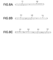
- the optical transmission line of the present invention (1) may be of a type where one span is comprised of a positive dispersion optical fiber and negative dispersion optical fiber, (2) may be of a type where one span is comprised of a positive dispersion optical fiber, negative dispersion optical fiber, and positive dispersion optical fiber so as to deal with two-way communications, or (3) may be of a type where one span is comprised of four or more fibers so as to keep down an increase in the cumulative dispersion.
- the configuration of the transmission line may be determined in accordance with the situation. In each case, more advantageous characteristics are obtained than the above loss characteristics.
- the lowest transmission loss of a conventional SMF+RDF type optical transmission line using an SMF for the front of the transmission line and an RDF for the rear which could be obtained in the 1.55 ⁇ m band was 0.215 dB/km.
- the reason was because despite the transmission loss of the positive dispersion optical fiber (SMF) being reduced down to 0.19 to 0.20 dB/km or so, the transmission loss of the RDF is a large 0.24 dB/km or more in the 1.55 ⁇ m band. With this, a reduction in the transmittable distance due to the transmission loss or non-linearity due to the increase in the input power to the RDF are incurred.
- SMF positive dispersion optical fiber
- the difference of the transmission losses of the positive dispersion optical fiber and negative dispersion optical fiber is preferably small. A difference of the transmission losses of more than 0.05 dB/km such as in a conventional dispersion management transmission line is not preferable.
- the inventors constructed a transmission line wherein not only the positive dispersion optical fiber, but also the negative dispersion optical fiber had a loss of not more than 0.23 dB/km and thereby reduced the difference in transmission losses between the two to not more than 0.05 dB/km, preferably 0.04 dB/km.
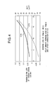
- the inventors connected a positive dispersion optical fiber 11 and a negative dispersion optical fiber 12 to construct a transmission line 1 and investigated the degree of wavelength distortion due to the non-linearity effect when increasing the difference of transmission losses between the positive dispersion optical fiber 11 positioned at the front of the transmission line 1 and the negative dispersion optical fiber 12 positioned at the rear while keeping the total transmission loss of the transmission line 1 constant.
- the inventors investigated how the wavelength distortion changed when increasing the difference in transmission losses while maintaining constant the ratio of lengths of the positive dispersion optical fiber 11 and negative dispersion optical fiber 12 making up the transmission line 1.
- the conditions for investigation are as follows: a total transmission loss of the transmission line 1 of 0.215 dB/km at the time of an effective core area A eff of the positive dispersion optical fiber 11 of 90 ⁇ m 2 , an effective core area A eff of the negative dispersion optical fiber 12 of 30 ⁇ m 2 , and, a length of the positive dispersion optical fiber 11 of 25 km and a length of the negative dispersion optical fiber 12 of 25 km, namely, a length of one span is 50km.
- the non-linearity becomes prominent from near a difference in transmission loss of 0.05 dB/km. Therefore, it was learned that the difference in transmission losses between the front positive dispersion optical fiber 11 and rear negative dispersion optical fiber 12 should be not more than 0.05 dB/km.
- a transmission loss of not more than 0.04 dB/km gives a higher linearity. Therefore, the difference in transmission losses is preferably not more than 0.04 dB/km.
- a conventional RDF generally tends to increase in transmission loss at the long wavelength side due to bending transmission loss.
- the transmission loss at 1580 nm tends to be considerably higher than the transmission loss at 1550 nm. This makes it difficult to adjust the difference in wavelength loss even at the time of C-Band transmission and becomes a serious disadvantage of increased transmission loss at the long wavelength side in the case of use of the L-Band.
- the inventors constructed a transmission line 1 comprised of a positive dispersion optical fiber 11 and negative dispersion optical fiber 12 both having a transmission loss of not more than 0.23 dB/km even in 1580 nm. Basically, by keeping the bending transmission loss of the negative dispersion optical fiber 12 a small value, it is possible to suppress an increase in transmission loss at the long wavelength side and provide a negative dispersion optical fiber 12 having a small bending transmission loss.
- the inventor constructed a transmission line of an optical fiber having a dispersion reduced from the conventional SMF or RDF in the 1.55 ⁇ m band.
- the absolute value of the dispersion was made not less than 10 ps/nm/km.
- the ability to reduce the absolute value of dispersion of the negative dispersion optical fiber means an increased freedom of design of the distribution of refractive index of the optical fiber (achievability even with a low relative refractive index difference ⁇ 1 between the cladding and core) and enables the transmission loss to be easily kept to a small value.
- the polarization mode dispersion (PMD) which is very dependent on the relative refractive index difference ⁇ 1, can also be kept to a small value.
- FIG. 3 is a graph showing the results of investigation of the relationship among the dispersion of the negative dispersion optical fiber (abscissa), transmission loss (curve CV1), and the polarization mode dispersion (PMD) (curve CV2).
- abcissa abbreviations
- CV1 transmission loss
- PMD polarization mode dispersion
- FIG. 3 it is learned that reduction of the dispersion has merits in the transmission loss and PMD. Therefore, the inventors constructed a transmission line by combining a positive dispersion fiber having a dispersion in the 1.55 ⁇ m band of 10 to 15 ps/nm/km or so and a negative dispersion optical fiber having a dispersion in the 1.55 ⁇ m band of -15 to -10 ps/nm/km or so. By this, it becomes possible to not only keep down the transmission loss, but also to keep the PMD down to a low value of for example not more than 0.06 ps/km 1/2 .
- the transmission loss of the positive dispersion optical fiber 11 is not only made not more than 0.23 dB/km, but also preferably made not more than the conventional record of 0.20 (preferably 0.195) dB/km. It was learned that the transmission loss of the negative dispersion optical fiber 12 is also preferably made not more than 0.225 dB/km by optimization of the design.
- the dispersion of the positive dispersion optical fiber 11 is 14 ps/nm/km and its transmission loss is 0.19 dB/km and the dispersion of the negative dispersion optical fiber 12 is -14 ps/nm/km and its transmission loss is 0.22 dB/km
- the total transmission loss of the transmission line 1 becomes 0.205 dB/km or so or an extremely low loss characteristic.
- the cumulative chromatic dispersion of the transmission line formed in this way is kept lower than that of an SMF+RDF type transmission line.
- the positive dispersion optical fiber 11 generally has a positive dispersion slope, so the negative dispersion optical fiber 12 is preferably given a negative dispersion slope.
- the dispersion slope of the positive dispersion optical fiber 11 is in almost all cases 0.06 to 0.08 ps/nm 2 /km, so if the dispersion slope of the negative dispersion optical fiber 12 is not more than -0.02 ps/nm 2 /km (preferably not more than -0.03 ps/nm 2 /km), with the optical transmission line 1 of the fifth embodiment of the present invention combining the positive dispersion optical fiber 11 and negative dispersion optical fiber 12, it becomes possible to achieve a low dispersion slope of not more than 0.03 ps/nm 2 /km- which was difficult to achieve with a conventional NZ-DSF type transmission line.
- constructing the optical transmission line 1 by combining the positive dispersion optical fiber 11 and negative dispersion optical fiber 12 has merits from the viewpoint of reducing the dispersion
- a small transmission loss and dispersion slope are extremely important in a transmission line. If the effective core area A eff is small, however, the disadvantage of non-linearity arises. Therefore, the inventor discovered that it is preferable to make the A eff of the front positive dispersion optical fiber 11 to which a stronger power is input at least 80 ⁇ m 2 (preferably at least 90 ⁇ m 2 ) and make the A eff of the rear negative dispersion optical fiber 12 to which the relatively weak power is input at least 30 ⁇ m 2 . In the rear optical fiber 12, however, the A eff must be of an extent not causing an increase in the transmission loss at the long wavelength side due to the bending transmission loss.
- the A eff is preferably 30 ⁇ m 2 to 34 ⁇ m 2 or so.
- the A eff is preferably 30 ⁇ m 2 to 34 ⁇ m 2 or so.
- the "bending transmission loss” means the increase in transmission loss at a certain wavelength when bending the optical transmission line by a certain diameter of curvature (in the example of FIG. 4, a curvature of 20 (mm ⁇ )).
- the inventors designed a positive dispersion optical fiber 11 and a negative dispersion optical fiber 12. As a result, they learned that the above characteristic can be obtained by a distribution of the refractive index of the step profile shown in FIG. 5, the segment core profile shown in FIG. 6, and the W+segment core profile shown in FIG. 7 for a positive dispersion optical fiber and the W+segment core profile shown in FIG. 7 for a negative dispersion optical fiber.
- the center core is located at the center.
- the "step profile" of FIG. 5 is a distribution of the refractive index comprised of a high refractive index center core positioned at the center and a flat side core with a smaller refractive index than the center core formed around it. A cladding with a smaller refractive index than the side core is formed around the side core.
- a typical positive dispersion optical fiber that is, a conventional SMF, has a simple two-layer structure comprised of a center core and a cladding provided around it.
- Such an SMF has a low relative refractive index difference ⁇ 1 between the refractive index of the core and refractive index of the cladding of 0.4%, so the A eff is large and a transmission loss of not more than 0.195 dB/km is achieved.
- Such an SMF generally has a dispersion in the 1.55 ⁇ m band of at least 16 ps/nm/km and therefore suffers from the disadvantage of a large dispersion.
- ⁇ 1 n 1 2 - n 0 2 2 n 1 2 ⁇ n 1 - n 0 n 1
- the inventors studied the suppression of the dispersion by a three-layer structure. If the refractive index of the center core is made small, the rise in the sensitivity (effect) with respect to the bending transmission loss not only causes the transmission loss to increase to at least 0.20 dB/km, but also the A eff ends up falling to not more than 80 ⁇ m 2 , so the relative refractive index difference ⁇ 1 was maintained at about 0.4% (for example, 0.35 to 0.45%).
- ⁇ 2 n 2 2 - n 0 2 2 n 2 2 ⁇ n 2 - n 0 n 2
- ⁇ 1 indicates the relative refractive index difference between the refractive index of the core and the refractive index of the cladding
- a indicates a parameter expressing the shape of the profile of the distribution of refractive index of the center core
- ⁇ 2 indicates the relative refractive index difference between the refractive index of the cladding and the refractive index of the side core
- b/a indicates the ratio of the diameter b of the side core to the diameter a of the center core
- Dispersion indicates the dispersion value
- Slope indicates the dispersion slope
- a eff indicates the effective core area
- ⁇ c indicates the cutoff wavelength
- Bending 20 indicates the bending transmission loss at 20 mm ⁇ .
- the inventors suppressed the dispersion to not more than 15 ps/nm/km, but they also tried studying structures having profiles of four or more layers shown in FIG. 6 and FIG. 7 aiming to further suppress the dispersion.
- they set the value of the relative refractive index difference ⁇ 1 between the cladding and the center core to about 0.4% and adjusted the parameters of the relative refractive index difference ⁇ 2 between the cladding and the side core, the relative refractive index difference ⁇ 3 between the cladding and the segment core, and the ratio a:b:c of the diameters so as to obtain the optimal A eff , ⁇ c , dispersion, etc.
- ⁇ 3 n 3 2 - n 0 2 2 n 3 2 ⁇ n 3 - n 0 n 3
- ⁇ 1 indicates the relative refractive index difference between the refractive index of the core and the refractive index of the cladding
- ⁇ indicates a parameter expressing the shape of the profile of the distribution of refractive index of the center core
- ⁇ 2 indicates the relative refractive index difference between the refractive index of the cladding and the refractive index of the side core
- ⁇ 3 indicates the relative refractive index difference between the refractive index of the cladding and the refractive index of the segment core
- a:b:c indicates the ratio of the diameter a of the center core, the diameter b of the side core, and the diameter c of the segment core
- Dispersion indicates the dispersion value
- Slope indicates the dispersion slope
- a eff indicates the effective core area
- ⁇ c indicates the cutoff wavelength
- Bending 20 indicates the bending transmission loss at 20 mm ⁇ .
- optical transmission lines having good characteristics could be obtained by the segment core type profile (FIG. 6) or the W+segment core type profile (FIG. 7).
- a conventional RDF uses a W-shape distribution of refractive index and reduces the relative refractive index difference ⁇ 1 until the limit of the bending transmission loss so as to achieve a low loss characteristic and a low dispersion. It would be possible to further reduce the transmission loss or absolute value of dispersion by reducing the relative refractive index difference ⁇ 1 further, but the bending transmission loss would become extremely large. By adding the segment core layer at the outside of the W-shape refractive index, however, the bending transmission loss can be suppressed. Therefore, the inventors used the W+segment core type profile such as shown in FIG.
- the inventors selected a value of about 0.85% (for example, 0.8 to 0.9%) as the apparent refractive difference ⁇ 1 between a cladding and center core satisfying a transmission loss of not more than 0.23 dB/km.
- the relative refractive index difference ⁇ 1 is not more than 0.80%, the transmission loss at the long wavelength side due to the increase of the bending transmission loss can occur.
- a parameter a expressing the shape of the profile of the distribution of the refractive index of the center core of around 2.0 (for example, 1.5 to 3.0) enables the dispersion slope to be made a small value of -0.030 ps/nm 2 /km or less.
- a relative refractive index difference ⁇ 2 of at least -0.45% is necessary, but it was learned that if the relative refractive index difference ⁇ 2 is not made -0.35% or less, the dispersion slope ends up becoming a large -0.03 ps/nm 2 /km or more.
- the relative refractive index difference ⁇ 3 has to be at least 0.15%, but if the relative refractive index difference ⁇ 3 exceeds 0.35%, the ⁇ c increases to 1500 nm or more and it no longer is possible to meet the single mode condition.
- the inventors adjusted the value of the ratio a:b:c of the diameter a of the center core, the diameter b of the side core, and the diameter c of the segment core.
- the ratio of a:b was 1:(1.7 to 1:2.0)
- a low bending transmission loss characteristic was obtained while maintaining a good value of other characteristics.
- less than the ratio of 1.7 it was learned that the dispersion characteristics became poor, while when more than 2.0, ⁇ c ended up becoming a large one of 1500 nm or more.
- ⁇ 1 indicates the relative refractive index difference between the refractive index of the core and the refractive index of the cladding
- a indicates a parameter expressing the shape of the profile of the distribution of refractive index of the center core
- ⁇ 2 indicates the relative refractive index difference between the refractive index of the cladding and the refractive index of the side core
- ⁇ 3 indicates the relative refractive index difference between the refractive index of the cladding and the refractive index of the segment core
- a:b:c indicates the ratio of the diameter a of the center core, the diameter b of the side core, and the diameter c of the segment core
- Dispersion indicates the dispersion value
- Slope indicates the dispersion slope
- a eff indicates the effective core area
- ⁇ c indicates the cutoff wavelength
- Bending 20 indicates the bending loss at a curvature of 20 mm.
- the inventors also studied whether the dispersion could be further suppressed for a negative dispersion optical fiber.
- it is effective to reduce the relative refractive index difference ⁇ 1 between the cladding and the center core to close to 0.70% (for example, 0.65% to 0.75%).
- a low relative refractive index difference ⁇ 1 invites an increase in the transmission loss at the long wavelength side.
- the parameter ⁇ expressing the shape of the profile of the distribution of refractive index of the center core was made about 10.
- the relative refractive index difference ⁇ 2 between the cladding and the side core has to be at least -0.50% in order to suppress the bending loss to not more than 10 dB/m (20 mm ⁇ ) while maintaining a low dispersion, but it was learned that if the relative refractive index difference ⁇ 2 is not made -0.40% or less, the dispersion slope ends up becoming a large one of more than -0.02 ps/nm 2 /km.
- the relative refractive index difference ⁇ 3 between the cladding and the segment core be 0.15% or more, but if the relative refractive index difference ⁇ 3 is over 0.25, the cutoff wavelength ⁇ c shifts to a long wavelength side and the single mode conditions can no longer be met.
- the inventors adjusted the ratio of a:b:c.
- the ratio of a:b was 1:1.8 to 1:2.2
- a low bending transmission loss characteristic of not more than 10 dB/m at 20 mm ⁇ could be obtained while maintaining good values of the other characteristics.
- the ratio of 1.8 was made 1:2.7 to 1:3.0.
- the bending transmission loss was not more than 10 dB/m (20 mm ⁇ ), or unimpaired, while maintaining a high compensation rate, while when less than 3.0, the cutoff wavelength ⁇ c was held to not more than 1500 nm. Therefore, a ratio of diameters (a:b:c) of 1:(1.8 to 2.2):(2.7 to 3.0) was selected.
- an optical transmission line by connecting the positive dispersion optical fiber 11 and negative dispersion optical fiber 12 shown in FIG. 1 of the present invention, a low non-linearity, low bending transmission loss characteristic, and a low dispersion slope are obtained. Further, since the optical transmission line 1 has a dispersion between that of the conventional RDF and NZ-DSF, the cumulative chromatic dispersion can be suppressed. Further, from the characteristics of the refractive index profile, the optical transmission line 1 achieves a low transmission loss characteristic over a broad range and a low PDM.
- the inventors developed a new type of optical transmission line combining a positive dispersion optical fiber and negative dispersion optical fiber and achieved a small cumulative chromatic dispersion, low non-linearity, low dispersion slope, and low PMD at the same time as a low transmission loss characteristic over a broad range.
- the characteristics of a low transmission loss, small cumulative chromatic dispersion, low PDM, low dispersion slope, and low non-linearity of this new optical transmission line are optimal for a high speed WDM transmission line.
- This new type of transmission line made using a positive dispersion optical fiber and negative dispersion optical fiber can be used to handle the bulk of future WDM transmission. Due to this, a transmission line suitable for high speed and large capacity transmission can be easily fabricated.
- test production was conducted to obtain positive dispersion optical fibers having the step profile illustrated in FIG. 5.
- the results of the test production conducted with reference to simulation are shown in Table 5.
- Table 5 Results of Test Production of Positive Dispersion Optical Fiber (Three-Layer Structure) 1.55 loss (dB/km) 1.58 loss (dB/km) Dispersion (ps/nm/km) Slope (ps/-nm 2 /km) A eff ( ⁇ m 2 ) ⁇ c (nm) Bending 20 ⁇ (dB/m) PMD (ps/- km 1/2 ) 1 0.193 0.191 14.6 0.070 96.5 1533 4.0 0.04 2 0.189 0.188 14.2 0.069 92.4 1546 3.5 0.04
- Prototypes 1 and 2 both had effective sectional areas A eff of at least 90 ⁇ m 2 and thereby obtained values of A eff enlarged over that of a conventional SMF. Further, the dispersion in the 1.55 ⁇ m band is suppressed from that of an SMF. In addition, the dispersions of Prototypes 1 and 2 were sufficiently large compared with a conventional NZ-DSF, so the signal noise due to the FWM can also be expected to be suppressed.
- the cutoff wavelength ⁇ c is somewhat large, but a value of not more than 1400 nm was obtained with measurement by the "22m method" which is measured the ⁇ c by using an optical fiber having a length of 22m.
- the dispersion slope, bending transmission loss, PMD, and other characteristics were also excellent.
- test production was conducted with reference to the results of the simulation for the four-layer structure profile as well. The results of the test production are shown in Table 6.
- Table 6 Results of Test Production of Positive Dispersion Optical Fiber (Four-Layer Structure) 1.55 loss (dB/km) 1.58 loss (dB/km) Dispersion (ps/nm/km) Slope (ps/-nm 2 /km) A eff ( ⁇ m 2 ) ⁇ c (nm) Bending 20 ⁇ (dB/m) PMD (ps/ -km 1/2 ) 1 0.194 0.199 12.6 0.067 84.5 1523 7.0 0.04 2 0.195 0.202 11.2 0.067 80.4 1510 9.5 0.05
- the optical transmission line of the present invention may be comprised of a plurality of spans of optical transmission lines 1, each span comprising a positive dispersion optical fiber 11 and negative dispersion optical fiber 12 connected together, connected for the necessary distance.
- each span may be comprised in various ways in addition to the combination of a positive dispersion optical fiber 11 and negative dispersion optical fiber 12 illustrated in FIG. 1.
- an optical transmission line comprised of spans each consisting of a positive dispersion optical fiber, negative dispersion optical fiber, and positive dispersion optical fiber.
- each span can be comprised of four or more fibers.
- the types and combinations of the optical fibers making up each span can be determined in accordance with the situation in line with the objective.
- Every optical transmission line of the embodiments can give advantageous characteristics due to the above transmission loss characteristics.
- every optical fiber exhibited a low PMD of 0.05 ps/km 1/2 or so. In this way, good results were obtained in terms of the total characteristics.
Landscapes
- Physics & Mathematics (AREA)
- Chemical & Material Sciences (AREA)
- Dispersion Chemistry (AREA)
- General Physics & Mathematics (AREA)
- Optics & Photonics (AREA)
- Optical Communication System (AREA)
- Optical Fibers, Optical Fiber Cores, And Optical Fiber Bundles (AREA)
Applications Claiming Priority (4)
| Application Number | Priority Date | Filing Date | Title |
|---|---|---|---|
| JP2001226054 | 2001-07-26 | ||
| JP2001226054 | 2001-07-26 | ||
| JP2002122826A JP3869305B2 (ja) | 2001-07-26 | 2002-04-24 | 光伝送路 |
| JP2002122826 | 2002-04-24 |
Publications (1)
| Publication Number | Publication Date |
|---|---|
| EP1279977A2 true EP1279977A2 (de) | 2003-01-29 |
Family
ID=26619322
Family Applications (1)
| Application Number | Title | Priority Date | Filing Date |
|---|---|---|---|
| EP02255092A Withdrawn EP1279977A2 (de) | 2001-07-26 | 2002-07-19 | Glasfaserübertragungsleitung mit Dispersionskompensation |
Country Status (5)
| Country | Link |
|---|---|
| US (1) | US6701051B2 (de) |
| EP (1) | EP1279977A2 (de) |
| JP (1) | JP3869305B2 (de) |
| CN (1) | CN100435503C (de) |
| CA (1) | CA2391187A1 (de) |
Cited By (1)
| Publication number | Priority date | Publication date | Assignee | Title |
|---|---|---|---|---|
| WO2005083484A1 (en) * | 2004-02-20 | 2005-09-09 | Corning Incorporated | Non-zero dispersion shifted optical fiber |
Families Citing this family (7)
| Publication number | Priority date | Publication date | Assignee | Title |
|---|---|---|---|---|
| EP1116970A1 (de) * | 1999-06-28 | 2001-07-18 | The Furukawa Electric Co., Ltd. | Optische übertragungsstrecke |
| JP4123823B2 (ja) * | 2002-05-17 | 2008-07-23 | 住友電気工業株式会社 | 分散補償ユニットおよび光通信システム |
| US20040234275A1 (en) * | 2003-05-20 | 2004-11-25 | Aref Chowdhury | Process for optical communication and system for same |
| KR100759805B1 (ko) * | 2005-12-07 | 2007-09-20 | 한국전자통신연구원 | 광증폭 듀플렉서 |
| JP4974161B2 (ja) * | 2007-07-27 | 2012-07-11 | 古河電気工業株式会社 | 光ファイバデバイス |
| JP5619516B2 (ja) | 2010-08-04 | 2014-11-05 | 古河電気工業株式会社 | 光ファイバ |
| CN112346174B (zh) | 2019-08-09 | 2022-12-02 | 华为技术有限公司 | 一种聚合物波导和太赫兹信号传输方法 |
Family Cites Families (4)
| Publication number | Priority date | Publication date | Assignee | Title |
|---|---|---|---|---|
| JPH09211511A (ja) | 1996-02-05 | 1997-08-15 | Furukawa Electric Co Ltd:The | 光通信システム |
| CA2232101A1 (en) * | 1997-03-25 | 1998-09-25 | Kazunori Mukasa | Dispersion compensating optical fiber, and wavelength division multiplex light transmission line using the same |
| WO2001063327A1 (en) * | 2000-02-24 | 2001-08-30 | Sumitomo Electric Industries, Ltd. | Optical transmission line and optical transmission system including it |
| JP4531954B2 (ja) | 2000-09-01 | 2010-08-25 | 古河電気工業株式会社 | 光ファイバおよびその光ファイバを用いた光伝送路 |
-
2002
- 2002-04-24 JP JP2002122826A patent/JP3869305B2/ja not_active Expired - Fee Related
- 2002-06-20 CA CA002391187A patent/CA2391187A1/en not_active Abandoned
- 2002-07-01 US US10/184,802 patent/US6701051B2/en not_active Expired - Lifetime
- 2002-07-19 EP EP02255092A patent/EP1279977A2/de not_active Withdrawn
- 2002-07-23 CN CNB021273863A patent/CN100435503C/zh not_active Expired - Fee Related
Cited By (2)
| Publication number | Priority date | Publication date | Assignee | Title |
|---|---|---|---|---|
| WO2005083484A1 (en) * | 2004-02-20 | 2005-09-09 | Corning Incorporated | Non-zero dispersion shifted optical fiber |
| US7024083B2 (en) | 2004-02-20 | 2006-04-04 | Corning Incorporated | Non-zero dispersion shifted optical fiber |
Also Published As
| Publication number | Publication date |
|---|---|
| CN100435503C (zh) | 2008-11-19 |
| CA2391187A1 (en) | 2003-01-26 |
| CN1400764A (zh) | 2003-03-05 |
| US20030063877A1 (en) | 2003-04-03 |
| JP3869305B2 (ja) | 2007-01-17 |
| JP2003107258A (ja) | 2003-04-09 |
| US6701051B2 (en) | 2004-03-02 |
Similar Documents
| Publication | Publication Date | Title |
|---|---|---|
| US6470126B1 (en) | Dispersion compensating optical fiber, and wavelength division multiplexing transmission line using a dispersion compensating optical fiber | |
| EP1241495A2 (de) | Optische Faser und Wellenlängenmultiplexübertragungsleitung | |
| US6591048B2 (en) | Dispersion compensating optical fiber and optical transmission line using the optical fiber | |
| US6684018B2 (en) | Low-dispersion optical fiber and optical transmission system using the low-dispersion optical fiber | |
| JPWO1999030193A1 (ja) | 分散フラット光ファイバ | |
| US6496631B2 (en) | Optical transmission line and optical transmission system including the same | |
| US6768848B2 (en) | Optical fiber and optical transmission line using the same, and optical transmission system | |
| JP4531954B2 (ja) | 光ファイバおよびその光ファイバを用いた光伝送路 | |
| US20010028774A1 (en) | Dispersion-shifted optical fiber | |
| EP1209495B1 (de) | Glasfaser und optisches Modul mit Dispersions-Kompensation | |
| EP1279977A2 (de) | Glasfaserübertragungsleitung mit Dispersionskompensation | |
| US6983094B2 (en) | Optical fiber and optical transmission system using such optical fiber | |
| JP2002277668A (ja) | 分散補償光ファイバおよびこれを用いた分散補償モジュールと光ファイバ複合伝送路 | |
| US6668121B2 (en) | Optical fiber, and dispersion compensator using same, optical transmission line using same and optical transmission system using same | |
| US6879762B2 (en) | Optical transmission line and optical transmission system using optical transmission line | |
| US6879763B2 (en) | Reverse dispersion optical fiber and optical transmission line using reverse dispersion optical fiber | |
| US6707971B2 (en) | Dispersion management optical transmission system and optical transmission line | |
| JP3479272B2 (ja) | 分散シフト光ファイバ及び光通信システム | |
| US6684017B1 (en) | Optical transmission line and optical transmission system including the same | |
| JP4205455B2 (ja) | 光ファイバ及びそれを用いた光伝送システム | |
| JP2003298520A (ja) | 分散マネージメント光伝送システムおよび光伝送路 |
Legal Events
| Date | Code | Title | Description |
|---|---|---|---|
| PUAI | Public reference made under article 153(3) epc to a published international application that has entered the european phase |
Free format text: ORIGINAL CODE: 0009012 |
|
| AK | Designated contracting states |
Designated state(s): AT BE BG CH CY CZ DE DK EE ES FI FR GB GR IE IT LI LU MC NL PT SE SK TR |
|
| AX | Request for extension of the european patent |
Extension state: AL LT LV MK RO SI |
|
| STAA | Information on the status of an ep patent application or granted ep patent |
Free format text: STATUS: THE APPLICATION HAS BEEN WITHDRAWN |
|
| 18W | Application withdrawn |
Effective date: 20040804 |