EP1282540B1 - Fahrzeugaufpralldämpfvorrichtung und verfahren zum transportieren dieser vorrichtung - Google Patents
Fahrzeugaufpralldämpfvorrichtung und verfahren zum transportieren dieser vorrichtung Download PDFInfo
- Publication number
- EP1282540B1 EP1282540B1 EP01932477A EP01932477A EP1282540B1 EP 1282540 B1 EP1282540 B1 EP 1282540B1 EP 01932477 A EP01932477 A EP 01932477A EP 01932477 A EP01932477 A EP 01932477A EP 1282540 B1 EP1282540 B1 EP 1282540B1
- Authority
- EP
- European Patent Office
- Prior art keywords
- impact attenuating
- vehicle
- attenuating device
- beams
- frame side
- Prior art date
- Legal status (The legal status is an assumption and is not a legal conclusion. Google has not performed a legal analysis and makes no representation as to the accuracy of the status listed.)
- Expired - Lifetime
Links
- 238000000034 method Methods 0.000 title claims description 4
- 230000008878 coupling Effects 0.000 claims description 22
- 238000010168 coupling process Methods 0.000 claims description 22
- 238000005859 coupling reaction Methods 0.000 claims description 22
- 239000000725 suspension Substances 0.000 claims description 15
- 238000005452 bending Methods 0.000 claims description 3
- 238000004891 communication Methods 0.000 claims description 2
- 238000005286 illumination Methods 0.000 claims description 2
- 238000004904 shortening Methods 0.000 claims 1
- 238000010276 construction Methods 0.000 description 6
- 230000004048 modification Effects 0.000 description 6
- 238000012986 modification Methods 0.000 description 6
- 239000002184 metal Substances 0.000 description 5
- 239000006096 absorbing agent Substances 0.000 description 4
- 230000008901 benefit Effects 0.000 description 4
- 230000035939 shock Effects 0.000 description 4
- 238000010521 absorption reaction Methods 0.000 description 3
- 239000013013 elastic material Substances 0.000 description 2
- 238000010422 painting Methods 0.000 description 2
- 230000002159 abnormal effect Effects 0.000 description 1
- 230000002238 attenuated effect Effects 0.000 description 1
- 230000033228 biological regulation Effects 0.000 description 1
- 230000008859 change Effects 0.000 description 1
- 230000002452 interceptive effect Effects 0.000 description 1
- 239000000463 material Substances 0.000 description 1
- 230000010355 oscillation Effects 0.000 description 1
- 239000002861 polymer material Substances 0.000 description 1
- 238000005096 rolling process Methods 0.000 description 1
- 125000006850 spacer group Chemical group 0.000 description 1
- 230000006641 stabilisation Effects 0.000 description 1
- 238000005406 washing Methods 0.000 description 1
Images






Classifications
-
- E—FIXED CONSTRUCTIONS
- E01—CONSTRUCTION OF ROADS, RAILWAYS, OR BRIDGES
- E01F—ADDITIONAL WORK, SUCH AS EQUIPPING ROADS OR THE CONSTRUCTION OF PLATFORMS, HELICOPTER LANDING STAGES, SIGNS, SNOW FENCES, OR THE LIKE
- E01F15/00—Safety arrangements for slowing, redirecting or stopping errant vehicles, e.g. guard posts or bollards; Arrangements for reducing damage to roadside structures due to vehicular impact
- E01F15/14—Safety arrangements for slowing, redirecting or stopping errant vehicles, e.g. guard posts or bollards; Arrangements for reducing damage to roadside structures due to vehicular impact specially adapted for local protection, e.g. for bridge piers, for traffic islands
- E01F15/145—Means for vehicle stopping using impact energy absorbers
- E01F15/148—Means for vehicle stopping using impact energy absorbers mobile arrangements
-
- B—PERFORMING OPERATIONS; TRANSPORTING
- B60—VEHICLES IN GENERAL
- B60R—VEHICLES, VEHICLE FITTINGS, OR VEHICLE PARTS, NOT OTHERWISE PROVIDED FOR
- B60R19/00—Wheel guards; Radiator guards, e.g. grilles; Obstruction removers; Fittings damping bouncing force in collisions
-
- B—PERFORMING OPERATIONS; TRANSPORTING
- B60—VEHICLES IN GENERAL
- B60R—VEHICLES, VEHICLE FITTINGS, OR VEHICLE PARTS, NOT OTHERWISE PROVIDED FOR
- B60R19/00—Wheel guards; Radiator guards, e.g. grilles; Obstruction removers; Fittings damping bouncing force in collisions
- B60R2019/005—Crash attenuators, i.e. means added to highway service vehicles for softening high speed impacts
Definitions
- the present invention relates to a crash attenuator or impact attenuating device to be connected to a vehicle with frame side members as well as a method of transporting such a device.
- Impact attenuating devices of this type are often referred to as TMAs (Truck Mounted Attenuators) or LMCCs (Lorry Mounted Crash Cushions).
- TMAs Trust Mounted Attenuators
- LMCCs Landing Mounted Crash Cushions
- An impact attenuator can also be used in moving roadworks, such as washing of reflecting posts and painting of road markings.
- the working vehicle moves slowly and sometimes stands still, which may result in unobservant road-users not having time to make way but colliding with the vehicle.
- the impact attenuator catches the vehicle and attenuates the collision forces by being deformed, for instance by means of metal constructions with deformation zones or elastic constructions of a polymer material.
- the EP publication discloses a device which is attached to the frame side members of a lorry and an attenuating part which consists of a deformable metal construction.
- the device is a single-service protection and is scrapped after a collision.
- the device has a rear part of an elastic material which can take up light impacts without damaging the more expensive attenuating part. During transport, the attenuating part and the rear part are raised by turning through 90 degrees to reduce the overhang and make driving easier.
- the US publication discloses an attenuating part of an elastic material, which allows it to be reused after a collision.
- the device is connected to a lorry by means of a plate which is mounted on the lorry and a wire from the rear part of the attenuating part to a stay on the lorry.
- the generic document US-A-4 770 420 reflects the most relevant prior art.
- the document discloses a vehicle mounting system for impact absorption apparatus.
- the system comprises an absorption box movably connected to a vehicle.
- the absorption box can be in a horizontal operational position or a vertical transport position.
- a problem in prior-art impact attenuating devices is that it is difficult to transport the attenuators between the roadwork areas.
- the attenuators are connected to the rear of the vehicle, which makes the distance between the rear axle of the vehicle and the rearmost point of the attenuator, the overhang, long, in most cases several meters.
- a long overhang causes great problems in sharp bends, intersections, roundabouts etc. As the vehicle turns, the overhang sweeps over a large area outside the vehicle's own lane, and in some traffic environments, it will be difficult to transport the device.
- a further problem is that great modifications of the vehicle are necessary for carrying prior-art attenuators. These modifications are not only expensive but also cause an inflexible system where only certain vehicles which have been modified in advance can use attenuators. Using today's system in which contractors are employed to a large extent, it is a great advantage to be able to call in any vehicle whatever and connect an attenuator.
- the object of the present invention is to provide an impact attenuating device which solves the above problems. According to the invention, this is achieved by a device comprising an attenuating part, a pair of wheels and a connecting part.
- the connecting part is arranged to connect the device to the vehicle in an operating position or a transport position. In transport position, the impact attenuating device behaves like a trailer.
- the connecting part comprises at least two beams for load take-up between the frame side members of the vehicle and the impact attenuating device and an extensible drawbar which is connected to the towing unit of the vehicle.
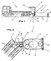
- Fig. 1 shows an impact attenuating device (1) consisting of a connecting part (2), an attenuating part (3) and wheels (4).
- the connecting part is connected to a vehicle (5) by means of a drawbar (6) which is connected to the towing unit (7) of the vehicle.
- the connecting part (2) When the connecting part (2) is in transport position (Fig. 1), the device (1) is only connected via the towing unit (7) of the vehicle and can pivot on the towing unit (7) as the vehicle turns (Fig. 2), i.e. it functions like a trailer.
- Fig. 3 shows the device (1) connected to the vehicle (5) in operating position.
- the drawbar (6) is retracted while at the same time two extensible beams (8) are pressed against the frame side members (9) of the vehicle.
- the pressure exerted on the frame side members (9) makes the device behave like a rigid extension of the vehicle.
- the device follows in a rigid manner and sweeps over a surface outside its own lane (Fig. 4).
- the wheels (4) have a pivot function, i.e. the wheels (4) can rotate on a vertical axis like the wheels of a shopping trolley.
- the pivot function is locked with the wheels (4) in the travelling direction.
- frame side member is meant in this application text on the one hand the frame side members of the vehicle and, on the other hand, beams and components which are arranged adjacent to the frame side members and can transfer an essentially horizontal load to the frame side members.
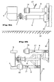
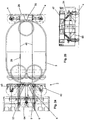
- Fig. 5 shows in more detail how the drawbar (6) is connected to the towing unit (7) of the vehicle.
- the drawbar (6) is telescopically extensible by means of a hydraulic cylinder (12).
- the drawbar is mounted round a beam (35) which is attached to a plate (33).
- the drawbar (6) is vertically displaceable along the beam (35).
- the Figure illustrates the currently most frequently used towing unit in Sweden, a VBG trailer coupling.
- the towing unit has an expanded opening (36) into which a male part (11) provided with a hole is inserted.
- a locking device (10) which with a pin through holes transversely of the opening (36) and through the male part (11) secures the parts to each other without preventing horizontal pivoting on the pin or a certain degree of vertical pivoting depending on irregularities in the roadway.
- Figs 6a-c illustrate a first embodiment of the coupling device between the beams (8) and the frame side members (9).
- the beams (8) are provided with a female part (14), and the frame side members with a male part (13).
- a locking device (15) secures the parts to each other.
- An advantage of this embodiment is that the female and male parts correspond to the same parts as are arranged on the towing unit (7) of the vehicle and the drawbar (6), in this case a VBG trailer coupling. Since the VBG trailer coupling of the beams is rotated through 90 degrees in relation to the vehicle towing unit, the coupling device can without difficulties take up oscillations in the vertical direction which arise when the wheels (4) of the attenuator roll over irregularities.
- Figs 7-9 Two other embodiments are shown in Figs 7-9.
- Fig. 7 illustrates both in the same Figure.
- a beam (8) is shown, which is pressed direct against the rear end of the frame side member (9) of the vehicle.
- the lower alternative has a conical male part (20) on the beam (8) which is pressed into a holder (19).
- the upper alternative requires no modification of the vehicle whereas the lower means that two holders (19) must be mounted on the frame side members. This is however a minor and inexpensive modification and gives an advantage by the possibility of arranging the beams (8) and the drawbar (6) in the same horizontal plane, which means that no bending moment in the vertical direction affects the towing unit and the drawbar in case of a collision.
- the embodiment shown in Figs 8a-b is the simplest and requires no modifications of the vehicle.
- the connecting part comprises a telescopic drawbar (6) and two telescopic beams (8). Both the drawbar and the beams can be raised and lowered to fit different towing units and frame side member heights.
- the first time the attenuator is connected to a new vehicle the pressure exerted on the frame side members is preset by means of a cylinder (18).
- the setting is carried out by the drawbar being shortened, after which the beams (8) are pressed against the frame side members with a suitable pressure by means of the cylinder (18).
- the cylinder (18) can be e.g. an ordinary lifting jack which is handled manually by means of a handle (17).
- the drawbar is shortened and the beams (8) are pressed against the frame side members using the preset pressure.
- Fig. 9 illustrates the lower embodiment in Fig. 7.
- Two holders (19) are mounted on the frame side members (9).
- the holders have conical openings into which conical male parts (20) are inserted in operating position.
- the cone coupling (19, 20) provides a rigid and safe connection between vehicle and attenuator.
- a hinge (21) is placed between the male coupling (20) and the beam (8).
- the hinge (21) can be resilient in the vertical direction when the wheels (4) are rolling over irregularities.
- a hydraulic cylinder (22) controls the telescopic beam (8) and holds the coupling (19, 20) under pressure.
- the beams (8) are horizontally movable by means of cranks (23).
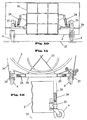
- Figs 10-12 illustrate the rear plate (26) of the attenuator with the wheel suspension mounted.
- the Figures illustrate an example with an adjustable spring system, which is especially usable together with the second embodiment of the coupling device. Since the beams and the drawbar in the second embodiment are not positioned in the same horizontal plane, a torque may arise which affects the rear end of the attenuator, which must be compensated for by means of the spring system.
- both an adjustable spring system and an ordinary spring system without adjusting possibilities can be used.
- the wheel suspension in Figs 10-12 comprises a spring system (24) including shock absorbers with a control system (25). In transport position, when the attenuator is connected like a trailer, the spring system serves as an ordinary trailer spring system.
- the wheels (4) have two functions, a pivot position and a fixed position.
- the pivot position is used in operation, and the fixed position is used during transport. Conveniently the change of position is effected automatically by means of pneumatics when changing from transport to operation and vice versa.
- Figs 10 and 11 indicate the two functions of the wheels (4) by showing a fixed wheel (4) and one where the pivot function is indicated by showing the wheel (4) in the three different positions.
- a suspension device in the form of a wire 27 arranged in a zigzag under the attenuating part (3).
- the wire is fixed to the rear plate (26) and to the front plate (33).
- Turnbuckles (28) are used to stretch the wire (27).
- the wire is fixed to the front plate (33) in safety catches (29) which are released when exposed to strain from a collision, thus releasing a further part of the wire.
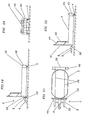
- Figs 13a-c show a second embodiment of the spring system and the wheel suspension.
- the shock absorbers (24) have no control system. This gives the advantage of a less expensive and simpler system, which means that for instance ordinary motorcycle or car shock absorbers can be used.
- Fig. 13a also shows a wheel suspension comprising an upper link arm (40) and a lower link arm (41).
- the construction using two parallel link arms causes the pivot axis (42) always to be vertical. If the pivot axis is inclined from its vertical position, the wheels will be unevenly loaded, which increases wear.
- the wheel suspension with pairs of link arms can also be used with an adjustable spring system.
- the attenuator is also provided with a holder (30) for traffic routing boards (31).
- the holder (30) is mounted on the plate (33) of the connecting part and consists of open square beams (35) into which the board (31) is inserted and secured.
- the regulations applicable to trailers must be complied with.
- the rear plate In transport position, the rear plate is therefore provided with signs and lighting for trailers. In operating position warning signs for service vehicles are provided.
- problems with stability during transport of the attenuator may in some cases arise, for instance in case of strong winds. This problem is solved by mounting supporting wheels or supporting rollers at the far end of the front plate (33). The wheels or rollers are mounted a distance above the roadway to provide support if the device tends to be inclined.
- Another solution is to mount a wheel axle with pivot wheels on the front plate (33) or the drawbar (6).
- a guard can be used.
- Figs 10 and 11 illustrate a guard in the form of a wire (34) which extends from the outer end of the wheel suspension to the outer end of the front plate (33).
- the guard can advantageously be more complete in the form a plurality of wires, a metal sheet, net or the like. If a reusable attenuating part is used, it may also be convenient to protect the attenuating part from being damaged in case of a collision.
- a guard in the form of a shell round the wheel suspension can reduce the risk of holes and scratches in the material.
- the impact attenuating device can also be used without a vehicle for stationary use.
- Fig. 14 shows how the device is arranged against some kind of stationary construction or mound of earth.
- the Figure shows that the connecting part has supporting wheels (32) which are lowered when the device is used without a vehicle, parked or handled manually. These wheels are mounted with a quick coupling and can be removed to save weight when the device is connected to a vehicle.
- FIG. 15 shows such an embodiment where the drawbar (6) has been removed and the beams (8) have been replaced by holders (38) suiting the plough mounting (39) of the vehicle.
- Fig. 16 shows an embodiment of the attenuator where pivot wheels (43) are arranged adjacent to the connecting part (2).
- the pivot wheels (43) are advantageously arranged on the plate (33) under the traffic routing board (31). These wheels preferably have some kind of spring system but do not need a locking function and are always in the pivot position.
- the attenuator is also provided with a vertically adjustable traffic routing board (31).
- the attenuator is in the operating position for e.g. exchange of roadlighting lamps, the traffic routing board (31) being raised to warn road-users.
- the traffic routing board (31) has arms (49) which control the motion up and down like a parallelogram.
- the arms (49) support a light board (48) with e.g. flash lamps and a light arrow.
- Fig. 17 shows the same embodiment as above, but in transport position.
- the attenuator is connected to the vehicle (5) via the vehicle towing unit (7) and the drawbar (6).
- the front pivot wheels (43) are still in the pivot position whereas the pivot function of the rear wheels (4) is locked.
- Fig. 18 shows like in Fig. 15 how the attenuator can be connected to the plough mounting (39) of the vehicle.
- a traffic routing board (31) is required, which does not obstruct the vehicle driver's view and in a suitable manner warns traffic coming the other way.
- the traffic routing board can be removed (see Fig. 15) while a light board or the like is arranged on the vehicle. It may also be appropriate to have warning signs behind the vehicle (5) or an attenuator (1) mounted in that place as well.
- Figs 19-22 illustrate one more embodiment of the connecting part (2) of the attenuator.
- the drawbar (6) and the beams (8) are connected to the attenuating part (3) by means of a hinge (50).
- Fig. 22 shows how the hinge (50) can be arranged on the front plate (33).
- the front pivot wheels (43) have been omitted to show more easily how the hinge (50) is arranged.
- the motion of the hinge in the vertical direction can also be restricted (see Fig. 23, a resilient restricting means (52)).
- Figs 19-22 also show one more embodiment of the rear plate (26) with accessories.
- the suspension consists of two parallel wires (46) from the rear plate (26) to the plate (33).
- a marking board (47) or sign with illumination is mounted on the rear plate (26).
- the rear plate is also widened so as to cover the entire width of the attenuating part (3). This means that the wheel suspension with spring system and locking etc. can be arranged protected within a cover (45).
- vehicles running into the attenuator strike a larger rear plate (26). This reduces the risk of the vehicle bouncing or sliding away from the attenuator without having been sufficiently attenuated.
- Figs 23-26 illustrate a preferred embodiment of the attenuator with pivot wheels (43) arranged adjacent to the connecting part (2).
- the drawbar (6) consists of a hydraulic cylinder which together with the beams (8) are connected to the plate (33) by means of a hinge (50).
- a resilient restricting means (52) is arranged between the plate (33) and the drawbar (6).
- the coupling device between the beams (8) and the frame side members (9) is simplified and consists of a fork-like part (53) at the outer end of the beams (8).
- the fork-like part (53) is conveniently designed for each individual vehicle in order to be as good a fit as possible.
- the fork-like part (53) surrounds the end of the frame side member, or a part associated with the frame side member, e.g. the beam for the vehicle towing unit (54).
- the inside of the fork-like part (53) is suitably covered with rubber, for instance by arranging a rubber block, thereby preventing metal from contacting metal in the connection.
- the stabilisation of the parts of the attenuator takes place by two parallel wires (44) arranged under the attenuating part (3).
- a spacer (55) is arranged between the attenuating part (3) and the rear plate (26) to provide space for the rear wheels (4) behind the rear plate (26).
- the rear plate (26) comprises a striking plate (56) with a check pattern and a marking board (47).
- the striking plate (56) can be made wider so as to cover the wheels (4) with suspension.
- the two rows of squares can be extended, for example, by one or two squares.
- the wheels (4) are arranged in such manner that the rearmost part of the wheel cannot move behind the rear plate (26). This prevents a vehicle from striking a wheel (4), sliding up on the wheel (4) and missing or incorrectly hitting the striking plate (56).
- This construction makes the wheel suspension and the spring system (24) protected behind the plate (26), see Fig. 26, where the wheel suspension and the associated spring system (24) are shown behind the plate (26).
- some kind of wireless communication e.g. radio
- the driver of the vehicle is equipped with a radio transceiver which then communicates with transceivers arranged at the different functions, sign, drawbar, locking of the pivot function etc.
Landscapes
- Engineering & Computer Science (AREA)
- Mechanical Engineering (AREA)
- Architecture (AREA)
- Civil Engineering (AREA)
- Structural Engineering (AREA)
- Vehicle Body Suspensions (AREA)
- Body Structure For Vehicles (AREA)
- Vibration Dampers (AREA)
- Disintegrating Or Milling (AREA)
- Handcart (AREA)
- Burglar Alarm Systems (AREA)
- Automobile Manufacture Line, Endless Track Vehicle, Trailer (AREA)
- Loading Or Unloading Of Vehicles (AREA)
- Vehicle Cleaning, Maintenance, Repair, Refitting, And Outriggers (AREA)
- Electric Propulsion And Braking For Vehicles (AREA)
Claims (23)
- Aufprall-Dämpfvorrichtung (1), die mit einem Fahrzeug (5) mit Rahmen-Seitenbauteilen (9) verbunden werden soll, wobei die Aufprall-Dämpfvorrichtung (1) ein Dämpfbauteil (3) und ein Verbindungsbauteil (2) aufweist, das mindestens zwei Träger (8) zur Aufnahme der Last zwischen den Rahmen-Seitenbauteilen (9) des Fahrzeugs (5) und der Aufprall-Dämpfvorrichtung aufweist, wobei die Aufprall-Dämpfvorrichtung (1) mit dem Fahrzeug (5) entweder in einer Betriebsposition oder in einer Transportposition verbunden ist, dadurch gekennzeichnet, dass die Aufprall-Dämpfvorrichtung (1) ein Paar Räder (4) sowie eine ausziehbare Deichsel (6) aufweist, die in der Transportposition mit einer Schleppeinheit (7) auf dem Fahrzeug (5) verbindbar ist, so dass die Aufprall-Dämpfvorrichtung (1) wie ein Anhänger mit dem Fahrzeug verbindbar ist.
- Aufprall-Dämpfvorrichtung nach Anspruch 1, dadurch gekennzeichnet, dass die Deichsel (6) teleskopisch ausziehbar ist und hydraulisch und/oder manuell eingestellt wird.
- Aufprall-Dämpfvorrichtung nach Anspruch 1 oder 2, dadurch gekennzeichnet, dass die Träger (8) und/oder die Deichsel (6) mit Hilfe eines Scharniers (50) gelenkig miteinander verbunden sind.
- Aufprall-Dämpfvorrichtung für Fahrzeuge nach einem der Ansprüche 1 bis 3, dadurch gekennzeichnet, dass die Träger (8) des Verbindungsbauteils in Betriebsposition derart an den Rahmen-Seitenbauteilen (9) des Fahrzeugs anliegen, dass das Fahrzeug (5) und die Aufprall-Dämpfvorrichtung (1) eine starre Einheit bilden.
- Aufprall-Dämpfvorrichtung nach Anspruch 4, dadurch gekennzeichnet, dass die Träger (8) gegen die Rahmen-Seiteribauteile mit einem festgelegten Druck gedrückt werden, indem die Deichsel verkürzt wird.
- Aufprall-Dämpfvorrichtung nach einem der Ansprüche 1 bis 3, dadurch gekennzeichnet, dass die Träger (8) des Verbindungsbauteils in Betriebsposition mit den Rahmen-Seitenbauteilen (9) des Fahrzeugs durch eine Kupplungsvorrichtung verbunden sind.
- Aufprall-Dämpfvorrichtung nach Anspruch 6, dadurch gekennzeichnet, dass die Kupplungsvorrichtung konische Buchsen-Bauteile (19) auf den Rahmen-Seitenbauteilen (9) aufweist, in welche konische Stecker-Bauteile (20) auf den Trägern (8) eingeführt werden.
- Aufprall-Dämpfvorrichtung nach Anspruch 6, dadurch gekennzeichnet, dass die Kupplungsvorrichtung Stecker-Bauteile (13) auf den Rahmen-Seitenbauteilen (9) aufweist, in welche Buchsen-Bauteile (14) auf den Trägern (8) eingeführt werden.
- Aufprall-Dämpfvorrichtung nach Anspruch 8, dadurch gekennzeichnet, dass die Kupplungsvorrichtung ein gabelähnliches Bauteil (53) auf den Trägern (8) aufweist.
- Aufprall-Dämpfvorrichtung nach einem der Ansprüche 6 bis 8, dadurch gekennzeichnet, dass die Kupplungsvorrichtung eine Verriegelungsvorrichtung (15) zur Befestigung der Träger (8) an den Seiten-Rahmenbauteilen (9) aufweist.
- Aufprall-Dämpfvorrichtung nach Anspruch 8 oder 10, dadurch gekennzeichnet, dass die Buchsen- und Steckerbauteile (13, 14) der Kupplungsvorrichtung einer Anhänger-Schleppeinheit, wie beispielsweise einer VBG-Anhängerkupplung, entsprechen.
- Aufprall-Dämpfvorrichtung nach einem der Ansprüche 6 bis 10, dadurch gekennzeichnet, dass es sich bei den Trägern um teleskopisch ausziehbare Träger handelt, die in Längsrichtung eingestellt werden können und die ein elastisches Scharnier (21) aufweisen, welches die durch die Vertikalabweichungen der Fahrbahn verursachten Biegungsmomente aufnimmt.
- Aufprall-Dämpfvorrichtung für Fahrzeuge nach einem der Ansprüche 1 bis 12, dadurch gekennzeichnet, dass die Räder (4) im Betrieb eine Schwenkfunktion haben, welche während des Transports gesperrt ist.
- Aufprall-Dämpfvorrichtung für Fahrzeuge nach einem der Ansprüche 1 bis 13, dadurch gekennzeichnet, dass die Räder (14) ein Federsystem (24) aufweisen.
- Aufprall-Dämpfvorrichtung nach Anspruch 14, dadurch gekennzeichnet, dass das Federsystem (24) ein Steuersystem (25) aufweist, welches das Federsystem während des Betriebs sperren kann.
- Aufprall-Dämpfvorrichtung nach einem der Ansprüche 1 bis 15, dadurch gekennzeichnet, dass das Verbindungsbauteil (2) ein oder mehrere Schwenkräder (43) aufweist.
- Aufprall-Dämpfvorrichtung nach einem der Ansprüche 1 bis 16, gekennzeichnet durch eine Befestigung für Verkehrsleit- und/oder Straßenschilder (31).
- Aufprall-Dämpfvorrichtung nach Anspruch 17, dadurch gekennzeichnet, dass das Verbindungsbauteil (2) Halterungen (30) für unterschiedliche Kombinationen von Schildern oder Tafeln (31) aufweist.
- Aufprall-Dämpfvorrichtung nach einem der Ansprüche 1 bis 18, gekennzeichnet durch eine Aufhängungseinrichtung in Form eines Drahtes (27), der das Paar Räder (4), das Dämpfbauteil (3) und das Verbindungsbauteil (2) durch eine Zickzack-Anordnung oder durch parallel verlaufende Drähte (46) verbindet.
- Aufprall-Dämpfvorrichtung nach Anspruch 19, dadurch gekennzeichnet, dass der Draht (27, 46) benachbart zu einer oder mehrerer seiner Befestigungen (29) eine Sperre oder Raste aufweist, die einen weiteren Abschnitt des Drahts freigeben kann.
- Aufprall-Dämpfvorrichtung nach einem der Ansprüche 1 bis 20, dadurch gekennzeichnet, dass eine oder mehrere der Funktionen der Aufprall-Dämpfvorrichtung, beispielsweise das Verriegeln/Entriegeln der Schwenkfunktion, Beleuchtung, Signalgebung, durch drahtlose Kommunikation (57), beispielsweise durch Funk, gesteuert werden.
- Verfahren zum Transportieren einer Aufprall-Dämpfvorrichtung (1), die mit einem Fahrzeug (5) mit Rahmen-Seitenbauteilen (9) verbunden werden soll, wobei die Aufprall-Dämpfvorrichtung (1) zwei Träger (8) zur Aufnahme der Last zwischen den Rahmen-Seitenbauteilen (9) des Fahrzeugs (5) und der Aufprall-Dämpfvorrichtung (1) während des Betriebs aufweist, dadurch gekennzeichnet, dass die Vorrichtung weiter ein Paar Räder (4) sowie eine ausziehbare Deichsel (6) aufweist, die während des Betriebs mit einer Schleppeinheit (7) auf dem Fahrzeug verbunden ist, so dass die Vorrichtung (1) ähnlich wie ein Anhänger mit dem Fahrzeug (5) verbunden ist.
- Verfahren nach Anspruch 22, dadurch gekennzeichnet, dass die Verbindung während des Transports mit der Schleppeinheit (7) des Fahrzeugs und während des Betriebs mit der Schleppeinheit (7) oder der Pflugbefestigung (39) des Fahrzeugs hergestellt wird.
Applications Claiming Priority (5)
| Application Number | Priority Date | Filing Date | Title |
|---|---|---|---|
| SE0001817 | 2000-05-17 | ||
| SE0001817A SE0001817D0 (sv) | 2000-05-17 | 2000-05-17 | Krockdämpande anordning för fordon samt metod |
| SE0003851 | 2000-10-24 | ||
| SE0003851A SE522192C2 (sv) | 2000-05-17 | 2000-10-24 | Krockdämpande anordning för fordon samt metod |
| PCT/SE2001/001099 WO2001087671A1 (en) | 2000-05-17 | 2001-05-17 | Crash attenuator for vehicle and method for transporting such attenuator |
Publications (2)
| Publication Number | Publication Date |
|---|---|
| EP1282540A1 EP1282540A1 (de) | 2003-02-12 |
| EP1282540B1 true EP1282540B1 (de) | 2005-10-26 |
Family
ID=26655110
Family Applications (1)
| Application Number | Title | Priority Date | Filing Date |
|---|---|---|---|
| EP01932477A Expired - Lifetime EP1282540B1 (de) | 2000-05-17 | 2001-05-17 | Fahrzeugaufpralldämpfvorrichtung und verfahren zum transportieren dieser vorrichtung |
Country Status (10)
| Country | Link |
|---|---|
| US (1) | US6866284B2 (de) |
| EP (1) | EP1282540B1 (de) |
| AT (1) | ATE307743T1 (de) |
| AU (1) | AU2001258999A1 (de) |
| CA (1) | CA2409099C (de) |
| DE (1) | DE60114409T2 (de) |
| DK (1) | DK1282540T3 (de) |
| NO (1) | NO326363B1 (de) |
| SE (1) | SE522192C2 (de) |
| WO (1) | WO2001087671A1 (de) |
Families Citing this family (27)
| Publication number | Priority date | Publication date | Assignee | Title |
|---|---|---|---|---|
| US6668989B2 (en) * | 1999-05-07 | 2003-12-30 | Safety By Design, Co. | Trailer mounted bursting energy absorption system |
| SE525249C2 (sv) * | 2002-12-20 | 2005-01-11 | Vaegverket | Krockdämpande anordning för fordon |
| US20040135828A1 (en) * | 2003-01-15 | 2004-07-15 | Schmitt Stephen E. | Printer and method for printing an item with a high durability and/or resolution image |
| US7063364B2 (en) * | 2003-03-10 | 2006-06-20 | Volvo Trucks North America, Inc. | Bumper arrangement |
| SE526813C2 (sv) * | 2004-03-04 | 2005-11-08 | Vaegverket | Krockdämpande anordning för fordon och metod |
| SE527538C2 (sv) * | 2004-03-22 | 2006-04-04 | Vaegverket | Kopplingsanordning för ett fordon |
| US7580915B2 (en) * | 2004-12-14 | 2009-08-25 | Sap Ag | Socket-like communication API for C |
| US7874572B2 (en) | 2005-01-10 | 2011-01-25 | Energy Absorption Systems, Inc. | Towable impact attenuator |
| US7341397B2 (en) * | 2005-07-18 | 2008-03-11 | Murphy William T | Utility trailer and safety barrier for street repair |
| US7784812B1 (en) * | 2006-05-23 | 2010-08-31 | Francisco Javier Lares | Central multi directional transmission system |
| US20070290515A1 (en) * | 2006-06-15 | 2007-12-20 | Doan Duc T | Extendable and retractable bumper protection apparatus |
| WO2008095048A1 (en) * | 2007-01-30 | 2008-08-07 | Traffix Devices, Inc. | Trailer mounted crash attenuator |
| US7441817B1 (en) * | 2007-04-23 | 2008-10-28 | Tma Acquisition, Llc | Trailer mounted crash attenuation system |
| US8974142B2 (en) | 2010-11-15 | 2015-03-10 | Energy Absorption Systems, Inc. | Crash cushion |
| IT1405174B1 (it) * | 2011-02-25 | 2013-12-20 | Salvemini | Sistema per la protezione dei cantieri assoggettati a traffico stradale o autostradale. |
| NL2008117C2 (nl) * | 2012-01-13 | 2013-07-16 | Verdegro Holding B V | Verplaatsbare (verkeers)signaleringsinrichting, voertuig voor het verplaatsen daarvan en werkwijze. |
| CN105555646B (zh) | 2013-09-11 | 2018-04-06 | 能量吸收系统公司 | 碰撞衰减器及使用其衰减来自撞击车辆的能量的方法 |
| US10319227B2 (en) | 2015-06-29 | 2019-06-11 | Royal Truck & Equipment, Inc. | Roadway work area safety truck |
| US11008717B2 (en) | 2015-06-29 | 2021-05-18 | Royal Truck & Equipment, Inc. | Safety truck attachments, and methods of safety truck use |
| US10995462B2 (en) * | 2018-10-10 | 2021-05-04 | International Business Machines Corporation | Autonomous mobile attenuator system |
| AU2019100368B4 (en) * | 2019-01-25 | 2019-11-28 | Norman BOYLE | A driverless impact attenuating traffic management vehicle |
| PE20221234A1 (es) | 2019-05-15 | 2022-08-12 | Trinity Highway Products Llc | Atenuador de golpes con conjunto de bisagra de placa de liberacion, conjunto de bisagra de placa de liberacion y metodo para el uso del mismo |
| CN112319404B (zh) * | 2020-11-17 | 2024-08-13 | 徐州徐工随车起重机有限公司 | 一种可调式防撞垫快速连接装置 |
| US12618209B2 (en) * | 2021-07-29 | 2026-05-05 | Concaten, Inc. | Emergency response barrier |
| CN113832895A (zh) * | 2021-11-04 | 2021-12-24 | 王志坚 | 一种保护车辆安全的道路桥梁弯道翻车自救装置 |
| PL442426A1 (pl) * | 2022-09-30 | 2024-04-02 | Wimed Spółka Z Ograniczoną Odpowiedzialnością Spółka Komandytowa | Wkład amortyzujący drogowego absorbera zderzeniowego oraz mobilny, drogowy absorber zderzeniowy z wkładem absorbującym |
| SE547886C2 (en) * | 2024-04-12 | 2025-12-16 | Berlex I Kungaelv Ab | Impact attenuator |
Family Cites Families (13)
| Publication number | Priority date | Publication date | Assignee | Title |
|---|---|---|---|---|
| US477420A (en) * | 1892-06-21 | Oscar jagobi | ||
| US4635981A (en) * | 1984-10-29 | 1987-01-13 | Energy Absorption Systems, Inc. | Impact attenuating body |
| US4770420A (en) | 1985-01-14 | 1988-09-13 | United Research And Manufacturing, Inc. | Vehicle mounting system for impact absorption apparatus |
| US5199755A (en) | 1991-04-03 | 1993-04-06 | Energy Absorption Systems, Inc. | Vehicle impact attenuating device |
| FR2722209B1 (fr) | 1994-07-11 | 1996-08-14 | Univ Pasteur | Recepteur opioide kappa humain, acides nucleiques et utilisations |
| FR2729979B1 (fr) * | 1995-01-26 | 1997-04-18 | Colas Sa | Remorque autonome de signalisation routiere et son panneau support de signalisation |
| US5697657A (en) | 1996-01-11 | 1997-12-16 | Albert W. Unrath, Inc. | Vehicle mounted crash attenuation system |
| US5947452A (en) * | 1996-06-10 | 1999-09-07 | Exodyne Technologies, Inc. | Energy absorbing crash cushion |
| US5823584A (en) | 1996-10-08 | 1998-10-20 | Vanderbilt University | Vehicle mounted crash impact attenuator |
| US6042135A (en) * | 1997-07-26 | 2000-03-28 | Ross; Louis J. | Hitch assembly and trailer |
| US6659491B2 (en) * | 2000-12-27 | 2003-12-09 | Ralph William Green | Trailer system |
| US6626449B2 (en) * | 2001-02-09 | 2003-09-30 | Donald B. Hazen | Double-castered wheel trailer having lockable caster wheels |
| WO2002096760A2 (en) * | 2001-05-30 | 2002-12-05 | Krauss Gerald W | Transportable storage container assembly |
-
2000
- 2000-10-24 SE SE0003851A patent/SE522192C2/sv not_active IP Right Cessation
-
2001
- 2001-05-17 DK DK01932477T patent/DK1282540T3/da active
- 2001-05-17 AT AT01932477T patent/ATE307743T1/de not_active IP Right Cessation
- 2001-05-17 WO PCT/SE2001/001099 patent/WO2001087671A1/en not_active Ceased
- 2001-05-17 AU AU2001258999A patent/AU2001258999A1/en not_active Abandoned
- 2001-05-17 EP EP01932477A patent/EP1282540B1/de not_active Expired - Lifetime
- 2001-05-17 CA CA002409099A patent/CA2409099C/en not_active Expired - Fee Related
- 2001-05-17 US US10/275,965 patent/US6866284B2/en not_active Expired - Fee Related
- 2001-05-17 DE DE60114409T patent/DE60114409T2/de not_active Expired - Fee Related
-
2002
- 2002-11-15 NO NO20025501A patent/NO326363B1/no unknown
Also Published As
| Publication number | Publication date |
|---|---|
| DK1282540T3 (da) | 2006-03-13 |
| NO326363B1 (no) | 2008-11-17 |
| SE0003851D0 (sv) | 2000-10-24 |
| DE60114409T2 (de) | 2006-07-20 |
| ATE307743T1 (de) | 2005-11-15 |
| NO20025501D0 (no) | 2002-11-15 |
| WO2001087671A1 (en) | 2001-11-22 |
| US6866284B2 (en) | 2005-03-15 |
| NO20025501L (no) | 2003-01-16 |
| AU2001258999A1 (en) | 2001-11-26 |
| US20040021294A1 (en) | 2004-02-05 |
| CA2409099A1 (en) | 2001-11-22 |
| CA2409099C (en) | 2008-11-25 |
| SE522192C2 (sv) | 2004-01-20 |
| DE60114409D1 (de) | 2005-12-01 |
| EP1282540A1 (de) | 2003-02-12 |
| SE0003851L (de) | 2001-11-18 |
Similar Documents
| Publication | Publication Date | Title |
|---|---|---|
| US6866284B2 (en) | Crash attenuator for vehicle and method for transporting such attenuator | |
| US12227911B2 (en) | Mobile barrier | |
| US7341397B2 (en) | Utility trailer and safety barrier for street repair | |
| US4616225A (en) | Portable traffic control signal device | |
| US4792258A (en) | Collapsible warning barricade apparatus | |
| US9394657B2 (en) | Mobile barrier | |
| CA2675749C (en) | Portable traffic barrier system | |
| US5475386A (en) | Portable folding standard and traffic signal apparatus | |
| US10240308B2 (en) | Mobile barrier | |
| US20040120760A1 (en) | Impact attenuating device for vehicle | |
| CA2656947A1 (en) | Reusable trailer mounted attenuator | |
| AU2014265099B2 (en) | Mobile barrier |
Legal Events
| Date | Code | Title | Description |
|---|---|---|---|
| PUAI | Public reference made under article 153(3) epc to a published international application that has entered the european phase |
Free format text: ORIGINAL CODE: 0009012 |
|
| 17P | Request for examination filed |
Effective date: 20021209 |
|
| AK | Designated contracting states |
Designated state(s): AT BE CH CY DE DK ES FI FR GB GR IE IT LI LU MC NL PT SE TR |
|
| AX | Request for extension of the european patent |
Extension state: AL LT LV MK RO SI |
|
| 17Q | First examination report despatched |
Effective date: 20041001 |
|
| GRAP | Despatch of communication of intention to grant a patent |
Free format text: ORIGINAL CODE: EPIDOSNIGR1 |
|
| GRAS | Grant fee paid |
Free format text: ORIGINAL CODE: EPIDOSNIGR3 |
|
| GRAA | (expected) grant |
Free format text: ORIGINAL CODE: 0009210 |
|
| AK | Designated contracting states |
Kind code of ref document: B1 Designated state(s): AT BE CH CY DE DK ES FI FR GB GR IE IT LI LU MC NL PT SE TR |
|
| PG25 | Lapsed in a contracting state [announced via postgrant information from national office to epo] |
Ref country code: LI Free format text: LAPSE BECAUSE OF FAILURE TO SUBMIT A TRANSLATION OF THE DESCRIPTION OR TO PAY THE FEE WITHIN THE PRESCRIBED TIME-LIMIT Effective date: 20051026 Ref country code: CH Free format text: LAPSE BECAUSE OF FAILURE TO SUBMIT A TRANSLATION OF THE DESCRIPTION OR TO PAY THE FEE WITHIN THE PRESCRIBED TIME-LIMIT Effective date: 20051026 |
|
| REG | Reference to a national code |
Ref country code: GB Ref legal event code: FG4D |
|
| REG | Reference to a national code |
Ref country code: CH Ref legal event code: EP |
|
| REG | Reference to a national code |
Ref country code: IE Ref legal event code: FG4D |
|
| REF | Corresponds to: |
Ref document number: 60114409 Country of ref document: DE Date of ref document: 20051201 Kind code of ref document: P |
|
| PG25 | Lapsed in a contracting state [announced via postgrant information from national office to epo] |
Ref country code: SE Free format text: LAPSE BECAUSE OF FAILURE TO SUBMIT A TRANSLATION OF THE DESCRIPTION OR TO PAY THE FEE WITHIN THE PRESCRIBED TIME-LIMIT Effective date: 20060126 Ref country code: GR Free format text: LAPSE BECAUSE OF FAILURE TO SUBMIT A TRANSLATION OF THE DESCRIPTION OR TO PAY THE FEE WITHIN THE PRESCRIBED TIME-LIMIT Effective date: 20060126 |
|
| PG25 | Lapsed in a contracting state [announced via postgrant information from national office to epo] |
Ref country code: ES Free format text: LAPSE BECAUSE OF FAILURE TO SUBMIT A TRANSLATION OF THE DESCRIPTION OR TO PAY THE FEE WITHIN THE PRESCRIBED TIME-LIMIT Effective date: 20060206 |
|
| REG | Reference to a national code |
Ref country code: DK Ref legal event code: T3 |
|
| REG | Reference to a national code |
Ref country code: CH Ref legal event code: PL |
|
| PG25 | Lapsed in a contracting state [announced via postgrant information from national office to epo] |
Ref country code: IE Free format text: LAPSE BECAUSE OF NON-PAYMENT OF DUE FEES Effective date: 20060517 |
|
| PG25 | Lapsed in a contracting state [announced via postgrant information from national office to epo] |
Ref country code: MC Free format text: LAPSE BECAUSE OF NON-PAYMENT OF DUE FEES Effective date: 20060531 |
|
| ET | Fr: translation filed | ||
| PLBE | No opposition filed within time limit |
Free format text: ORIGINAL CODE: 0009261 |
|
| STAA | Information on the status of an ep patent application or granted ep patent |
Free format text: STATUS: NO OPPOSITION FILED WITHIN TIME LIMIT |
|
| 26N | No opposition filed |
Effective date: 20060727 |
|
| REG | Reference to a national code |
Ref country code: IE Ref legal event code: MM4A |
|
| PG25 | Lapsed in a contracting state [announced via postgrant information from national office to epo] |
Ref country code: TR Free format text: LAPSE BECAUSE OF FAILURE TO SUBMIT A TRANSLATION OF THE DESCRIPTION OR TO PAY THE FEE WITHIN THE PRESCRIBED TIME-LIMIT Effective date: 20051026 Ref country code: LU Free format text: LAPSE BECAUSE OF NON-PAYMENT OF DUE FEES Effective date: 20060517 |
|
| PGFP | Annual fee paid to national office [announced via postgrant information from national office to epo] |
Ref country code: DE Payment date: 20080527 Year of fee payment: 8 Ref country code: DK Payment date: 20080530 Year of fee payment: 8 |
|
| PGFP | Annual fee paid to national office [announced via postgrant information from national office to epo] |
Ref country code: AT Payment date: 20080520 Year of fee payment: 8 |
|
| PGFP | Annual fee paid to national office [announced via postgrant information from national office to epo] |
Ref country code: BE Payment date: 20080526 Year of fee payment: 8 Ref country code: PT Payment date: 20080514 Year of fee payment: 8 Ref country code: FI Payment date: 20080522 Year of fee payment: 8 Ref country code: IT Payment date: 20080514 Year of fee payment: 8 |
|
| PGFP | Annual fee paid to national office [announced via postgrant information from national office to epo] |
Ref country code: NL Payment date: 20080529 Year of fee payment: 8 |
|
| PG25 | Lapsed in a contracting state [announced via postgrant information from national office to epo] |
Ref country code: CY Free format text: LAPSE BECAUSE OF FAILURE TO SUBMIT A TRANSLATION OF THE DESCRIPTION OR TO PAY THE FEE WITHIN THE PRESCRIBED TIME-LIMIT Effective date: 20051026 |
|
| PGFP | Annual fee paid to national office [announced via postgrant information from national office to epo] |
Ref country code: GB Payment date: 20080523 Year of fee payment: 8 |
|
| PGFP | Annual fee paid to national office [announced via postgrant information from national office to epo] |
Ref country code: FR Payment date: 20090528 Year of fee payment: 9 |
|
| REG | Reference to a national code |
Ref country code: PT Ref legal event code: MM4A Free format text: LAPSE DUE TO NON-PAYMENT OF FEES Effective date: 20091117 |
|
| BERE | Be: lapsed |
Owner name: *VAGVERKET Effective date: 20090531 |
|
| REG | Reference to a national code |
Ref country code: DK Ref legal event code: EBP |
|
| GBPC | Gb: european patent ceased through non-payment of renewal fee |
Effective date: 20090517 |
|
| PG25 | Lapsed in a contracting state [announced via postgrant information from national office to epo] |
Ref country code: FI Free format text: LAPSE BECAUSE OF NON-PAYMENT OF DUE FEES Effective date: 20090517 Ref country code: AT Free format text: LAPSE BECAUSE OF NON-PAYMENT OF DUE FEES Effective date: 20090517 |
|
| NLV4 | Nl: lapsed or anulled due to non-payment of the annual fee |
Effective date: 20091201 |
|
| PG25 | Lapsed in a contracting state [announced via postgrant information from national office to epo] |
Ref country code: NL Free format text: LAPSE BECAUSE OF NON-PAYMENT OF DUE FEES Effective date: 20091201 |
|
| PG25 | Lapsed in a contracting state [announced via postgrant information from national office to epo] |
Ref country code: PT Free format text: LAPSE BECAUSE OF NON-PAYMENT OF DUE FEES Effective date: 20091117 |
|
| PG25 | Lapsed in a contracting state [announced via postgrant information from national office to epo] |
Ref country code: DK Free format text: LAPSE BECAUSE OF NON-PAYMENT OF DUE FEES Effective date: 20090531 |
|
| PG25 | Lapsed in a contracting state [announced via postgrant information from national office to epo] |
Ref country code: GB Free format text: LAPSE BECAUSE OF NON-PAYMENT OF DUE FEES Effective date: 20090517 |
|
| PG25 | Lapsed in a contracting state [announced via postgrant information from national office to epo] |
Ref country code: DE Free format text: LAPSE BECAUSE OF NON-PAYMENT OF DUE FEES Effective date: 20091201 Ref country code: BE Free format text: LAPSE BECAUSE OF NON-PAYMENT OF DUE FEES Effective date: 20090531 |
|
| REG | Reference to a national code |
Ref country code: FR Ref legal event code: ST Effective date: 20110131 |
|
| PG25 | Lapsed in a contracting state [announced via postgrant information from national office to epo] |
Ref country code: IT Free format text: LAPSE BECAUSE OF NON-PAYMENT OF DUE FEES Effective date: 20090517 |
|
| PG25 | Lapsed in a contracting state [announced via postgrant information from national office to epo] |
Ref country code: FR Free format text: LAPSE BECAUSE OF NON-PAYMENT OF DUE FEES Effective date: 20100531 |