EP1283373B1 - Struktur gegen das lösen von befestigungsteilen mit gewinde - Google Patents
Struktur gegen das lösen von befestigungsteilen mit gewinde Download PDFInfo
- Publication number
- EP1283373B1 EP1283373B1 EP01932163A EP01932163A EP1283373B1 EP 1283373 B1 EP1283373 B1 EP 1283373B1 EP 01932163 A EP01932163 A EP 01932163A EP 01932163 A EP01932163 A EP 01932163A EP 1283373 B1 EP1283373 B1 EP 1283373B1
- Authority
- EP
- European Patent Office
- Prior art keywords
- bolt
- washer
- nut
- tightening
- trunk
- Prior art date
- Legal status (The legal status is an assumption and is not a legal conclusion. Google has not performed a legal analysis and makes no representation as to the accuracy of the status listed.)
- Expired - Lifetime
Links
- 230000003405 preventing effect Effects 0.000 title claims description 23
- 239000000853 adhesive Substances 0.000 description 12
- 230000001070 adhesive effect Effects 0.000 description 12
- 210000000078 claw Anatomy 0.000 description 12
- 230000000630 rising effect Effects 0.000 description 9
- 239000002775 capsule Substances 0.000 description 3
- 238000004519 manufacturing process Methods 0.000 description 2
- 230000000694 effects Effects 0.000 description 1
- 238000000034 method Methods 0.000 description 1
- 230000010355 oscillation Effects 0.000 description 1
- 238000003825 pressing Methods 0.000 description 1
Images


Classifications
-
- F—MECHANICAL ENGINEERING; LIGHTING; HEATING; WEAPONS; BLASTING
- F16—ENGINEERING ELEMENTS AND UNITS; GENERAL MEASURES FOR PRODUCING AND MAINTAINING EFFECTIVE FUNCTIONING OF MACHINES OR INSTALLATIONS; THERMAL INSULATION IN GENERAL
- F16B—DEVICES FOR FASTENING OR SECURING CONSTRUCTIONAL ELEMENTS OR MACHINE PARTS TOGETHER, e.g. NAILS, BOLTS, CIRCLIPS, CLAMPS, CLIPS OR WEDGES; JOINTS OR JOINTING
- F16B39/00—Locking of screws, bolts or nuts
- F16B39/22—Locking of screws, bolts or nuts in which the locking takes place during screwing down or tightening
- F16B39/28—Locking of screws, bolts or nuts in which the locking takes place during screwing down or tightening by special members on, or shape of, the nut or bolt
- F16B39/32—Locking by means of a pawl or pawl-like tongue
-
- F—MECHANICAL ENGINEERING; LIGHTING; HEATING; WEAPONS; BLASTING
- F16—ENGINEERING ELEMENTS AND UNITS; GENERAL MEASURES FOR PRODUCING AND MAINTAINING EFFECTIVE FUNCTIONING OF MACHINES OR INSTALLATIONS; THERMAL INSULATION IN GENERAL
- F16B—DEVICES FOR FASTENING OR SECURING CONSTRUCTIONAL ELEMENTS OR MACHINE PARTS TOGETHER, e.g. NAILS, BOLTS, CIRCLIPS, CLAMPS, CLIPS OR WEDGES; JOINTS OR JOINTING
- F16B39/00—Locking of screws, bolts or nuts
- F16B39/02—Locking of screws, bolts or nuts in which the locking takes place after screwing down
- F16B39/028—Locking of screws, bolts or nuts in which the locking takes place after screwing down by means of an auxiliary bolt or threaded element whose action provokes the deformation of the main bolt or nut and thereby its blocking
-
- F—MECHANICAL ENGINEERING; LIGHTING; HEATING; WEAPONS; BLASTING
- F16—ENGINEERING ELEMENTS AND UNITS; GENERAL MEASURES FOR PRODUCING AND MAINTAINING EFFECTIVE FUNCTIONING OF MACHINES OR INSTALLATIONS; THERMAL INSULATION IN GENERAL
- F16B—DEVICES FOR FASTENING OR SECURING CONSTRUCTIONAL ELEMENTS OR MACHINE PARTS TOGETHER, e.g. NAILS, BOLTS, CIRCLIPS, CLAMPS, CLIPS OR WEDGES; JOINTS OR JOINTING
- F16B39/00—Locking of screws, bolts or nuts
- F16B39/02—Locking of screws, bolts or nuts in which the locking takes place after screwing down
- F16B39/10—Locking of screws, bolts or nuts in which the locking takes place after screwing down by a plate, spring, wire or ring immovable with regard to the bolt or object and mainly perpendicular to the axis of the bolt
- F16B39/103—Locking of screws, bolts or nuts in which the locking takes place after screwing down by a plate, spring, wire or ring immovable with regard to the bolt or object and mainly perpendicular to the axis of the bolt with a locking cup washer, ring or sleeve surrounding the nut or bolt head and being partially deformed on the nut or bolt head, or on the object itself
-
- F—MECHANICAL ENGINEERING; LIGHTING; HEATING; WEAPONS; BLASTING
- F16—ENGINEERING ELEMENTS AND UNITS; GENERAL MEASURES FOR PRODUCING AND MAINTAINING EFFECTIVE FUNCTIONING OF MACHINES OR INSTALLATIONS; THERMAL INSULATION IN GENERAL
- F16B—DEVICES FOR FASTENING OR SECURING CONSTRUCTIONAL ELEMENTS OR MACHINE PARTS TOGETHER, e.g. NAILS, BOLTS, CIRCLIPS, CLAMPS, CLIPS OR WEDGES; JOINTS OR JOINTING
- F16B39/00—Locking of screws, bolts or nuts
- F16B39/02—Locking of screws, bolts or nuts in which the locking takes place after screwing down
- F16B39/10—Locking of screws, bolts or nuts in which the locking takes place after screwing down by a plate, spring, wire or ring immovable with regard to the bolt or object and mainly perpendicular to the axis of the bolt
- F16B39/108—Locking of screws, bolts or nuts in which the locking takes place after screwing down by a plate, spring, wire or ring immovable with regard to the bolt or object and mainly perpendicular to the axis of the bolt with a locking washer under the nut or bolt head having at least one tongue or lug folded against the nut or bolt head, or against the object itself
-
- F—MECHANICAL ENGINEERING; LIGHTING; HEATING; WEAPONS; BLASTING
- F16—ENGINEERING ELEMENTS AND UNITS; GENERAL MEASURES FOR PRODUCING AND MAINTAINING EFFECTIVE FUNCTIONING OF MACHINES OR INSTALLATIONS; THERMAL INSULATION IN GENERAL
- F16B—DEVICES FOR FASTENING OR SECURING CONSTRUCTIONAL ELEMENTS OR MACHINE PARTS TOGETHER, e.g. NAILS, BOLTS, CIRCLIPS, CLAMPS, CLIPS OR WEDGES; JOINTS OR JOINTING
- F16B39/00—Locking of screws, bolts or nuts
- F16B39/22—Locking of screws, bolts or nuts in which the locking takes place during screwing down or tightening
- F16B39/24—Locking of screws, bolts or nuts in which the locking takes place during screwing down or tightening by means of washers, spring washers, or resilient plates that lock against the object
-
- F—MECHANICAL ENGINEERING; LIGHTING; HEATING; WEAPONS; BLASTING
- F16—ENGINEERING ELEMENTS AND UNITS; GENERAL MEASURES FOR PRODUCING AND MAINTAINING EFFECTIVE FUNCTIONING OF MACHINES OR INSTALLATIONS; THERMAL INSULATION IN GENERAL
- F16B—DEVICES FOR FASTENING OR SECURING CONSTRUCTIONAL ELEMENTS OR MACHINE PARTS TOGETHER, e.g. NAILS, BOLTS, CIRCLIPS, CLAMPS, CLIPS OR WEDGES; JOINTS OR JOINTING
- F16B39/00—Locking of screws, bolts or nuts
- F16B39/22—Locking of screws, bolts or nuts in which the locking takes place during screwing down or tightening
- F16B39/28—Locking of screws, bolts or nuts in which the locking takes place during screwing down or tightening by special members on, or shape of, the nut or bolt
- F16B39/282—Locking by means of special shape of work-engaging surfaces, e.g. notched or toothed nuts
Definitions
- the present invention relates to a structure or an assembly for preventing loosening of bolts or nuts after tightening by a screw-fastening tool for tightening a plurality of members together by using bolts or a set of bolts and nuts.
- Bolts prevented from loosening through application of adhesive on screw portions of bolts or nuts prevented from loosening such as Hard Locks (trade name) or U-nuts (trade name) are conventionally known to be commercially available. However, such products are arranged in that bolts or nuts are particularly treated or processed and are not adaptable for bolts or nuts of standard type.
- square portions are integrally formed on trunks or shanks of bolts while piercing holes of members to be tightened are formed to be of noncircular shape that fit the square portions of the trunks. Since the fit between the square portions of trunks and the noncircular piercing holes will restrain rotation of bolts, it will be unnecessary to fix head portions of the bolts by using wrenches or similar in case the nuts are to be tightened. Thus, tightening operations can be easily performed when employing this structure.
- a structure has been suggested in which a protrusion is integrally formed on a trunk of a bolt whereupon this protrusion is inserted into a clearance formed between a circular piercing hole of a member to be tightened and the trunk of the bolt (See Japanese Examined Patent Publication No. 2-114742(1990) and U.S. Patent No. 5,158,409).
- the protrusion of the bolt has a height that is larger than 1/2 of a difference between a diameter of the trunk and a diameter of the piercing hole so that the bolt eccentrically rotates when rotating within the piercing hole with the center being somewhat shifted from a central axis of the trunk or shank, thus making a head portion of the bolt slide on a bearing surface while continuously being shifted in a lateral direction.
- tightening the nut upon screwing the nut into the bolt will result in a larger sliding resistance between the head portion and the bearing surface of the bolt so that the bolt is not allowed to further move upon shifting in lateral directions whereupon the rotation of the bolt will be terminated.
- US-A-6155409 discloses a structure for preventing loosening of a serew-fastening tool comprising a first member including a piercing hole, a second member including a screw hole, and a bolt including a head portion and a trunk, wherein the first member and the second member are tightened together by inserting the trunk of the bolt through the piercing hole of the first member, screwing the same into the screw hole of the second member and tightening the bolt.
- the invention provides a structure for preventing loosening of a screw threaded fastener as claimed in claim 1 or claim 3.
- the present invention is arranged to prevent loosening by means of washers disposed on bearing surfaces of bolts or nuts, the present invention is also applicable to bolts or nuts of standard type such that manufacturing costs may be kept relatively low. It is also applicable to screw-threaded fasteners employing bolts or sets of bolts and nuts. It is possible to exhibit loosening preventing effects without the necessity of performing any particular processing or operation after tightening. Economical advantages may be achieved since the washers may be used instead of ordinary washers.
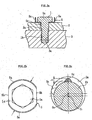
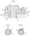
- Figs. 1 and 2 illustrate a first embodiment of the present invention.
- Fig. 1 illustrates a condition after completion of tightening and
- Fig. 2 a condition at the time of tightening.
- a trunk 1b of a bolt 1 pierces through a circular piercing hole 2a of a member 2 to be tightened and is screwed into a screw hole 3a of a member 3 to be tightened.
- a head portion 1a of the bolt 1 is of hexagonal shape and a washer 5 is interposed between a bearing surface thereof and an upper surface of the member 2 to be tightened.
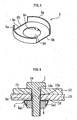
- the washer 5 is formed upon stamping, for instance, a metallic plate as illustrated in Fig.
- the flat plate portion 5e of the washer 5 is interposed between the head portion 1a of the bolt 1 and the upper surface of the member 2 to be tightened.
- the projecting portion 5c of the washer is inserted into a clearance formed between the trunk 1b of the bolt 1 and the piercing hole 2a of the member 2 to be tightened. As shown in Fig.
- a height h of the projecting portion 5c is larger than 1/2 of a difference between a diameter of the trunk 1b and a diameter of the piercing hole 2a, and a center of axis 01 of the trunk 1b is thus shifted from the center 02 of the piercing hole 2a, and the clearance between the trunk 1b and the piercing hole 2a is of wedged-shape in which it becomes gradually smaller in approaching both sides in a rotating direction.
- Each rising portion 5a of the washer 5 is lower than a height of the head portion 1a of the bolt 1 and is located so as not to interfere the head portion 1a.
- the bolt 1 may still be relatively rotated with respect to the washer 5 in this condition.
- Tightening of the members 2 and 3 to be tightened is performed in the following manner.
- the hole 5d of the washer 5 is first put against the piercing hole 2a of the member 2 to be tightened (the projecting portion 5c is inserted into the piercing hole 2a) whereupon the trunk 1b of the bolt 1 is passed through the hole 5d of the washer 5 and the piercing hole 2a of the member 2 to be tightened to be screwed at the screw hole 3a of the member 3 to be tightened.
- the bolt 1 is then rotated into a tightening direction for screwing a screw portion of the trunk 1b into the screw hole 3a of the member 3 to be tightened and accordingly tightening the members 2 and 3 to be tightened together.
- the bolt 1 and the washer 5 may be relatively rotated in this condition, the bolt 1 rotates within the piercing hole 2a around the center of axis 01 of the trunk 1b without being restrained by the washer 5.
- tightening may be performed just like with an ordinary bolt.
- the engaging portions 5b of the washer 5 are engaged using a suitable tool while pressurizing the head portion 1a of the bolt 1 by a suitable tool, and as shown in Fig. 2c, the washer 5 is then rotated in a direction of loosening the bolt 1 (counter-clockwise in the drawing) for press-fitting the projecting portion 5c into the wedge-like clearance in this direction.
- the rising portions 5a of the washer are swaged as shown in Fig. 1 and the swaged portions 5a1 are engaged with an outer periphery of the head portion 1a of the bolt 1.
- the bolt 1 and the washer 5 are integrated such that they cannot be relatively rotated and loosening of the bolt 1 is prevented by the washer 5. More particularly, as shown in Fig.
- the bolt 1 is thus not allowed to rotate in a loosening direction so that loosening thereof is prevented.
- the projecting portion 5c of the washer 5 might be dimensioned to be short in a circumferential direction as shown in Fig. 13a or to be long in the circumferential direction as shown in Fig. 13b.
- a rotational angle in a loosening direction for the bolt 1 may be reduced.
- Fig. 4 illustrates a second embodiment of the present invention.
- This embodiment is arranged in that the washer 5 of the first embodiment is applied to a nut 6.
- the trunk 1b of the bolt 1 pierces through a circular piercing hole 12a of a member 12 to be tightened and a circular piercing hole 13a of a member 13 to be tightened to be screwed into the hexagonal nut 6.
- the flat plate portion 5e of the washer 5 is interposed between a bearing surface of the nut 6 and a lower surface of the member 13 to be tightened.
- the nut 6 is rotated in a tightening direction for screwing the same into the screw portion of the trunk 1b of the bolt 1 for tightening the members 12 and 13 to be tightened together.
- a suitable tool is engaged with the engaging portions 5b of the washer 5 while pressing the nut 6 by a suitable tool, and the washer 5 is rotated in a direction for loosening the nut 6 such that the projecting portion 5c is press-fitted into a wedge-like clearance between the trunk 1b and the piercing hole 13a.
- the rising portions 5a of the washer 5 are swaged and the swaged portions 5a1 are engaged with an outer periphery of the nut 6 for integrating the nut 6 and the washer 5.
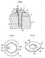
- Fig. 5 illustrates a third embodiment. This embodiment is arranged in that the bolt 1 and a washer 15 are prevented from relative rotation through a screw 1a2 after tightening of the bolt 1.
- the screw 1a2 is screwed into a screw hole 1a1 provided on the head portion 1a of the bolt 1. Relative rotation of both members is prevented through a tip end of the screw 1a2 press-contacting the washer 15. As shown in Fig.
- the washer 15 of the present embodiment may be formed by, for instance, stamping a metallic plate, and comprises a flat plate portion 15e, a pair of linear engaging portions 15b provided on an edge of the flat plate portion 15e, a hole 15d formed in the center of the flat plate portion 15e, and a projecting portion 15e projecting downward from an inner edge of the hole 15d.
- stamping a metallic plate and comprises a flat plate portion 15e, a pair of linear engaging portions 15b provided on an edge of the flat plate portion 15e, a hole 15d formed in the center of the flat plate portion 15e, and a projecting portion 15e projecting downward from an inner edge of the hole 15d.
- Fig. 6 illustrates a fourth embodiment. This embodiment is arranged in that the washer 15 of the third embodiment is applied to the nut 6. A screw 6b is screwed into a screw hole 6a provided in the nut 6. The remaining matters apply correspondingly to the first to third embodiments.
- Fig. 7 illustrates a fifth embodiment.
- the washer is comprised of a first washer 7 and a second washer 8.
- the washer 7 is formed by, for instance, stamping a metallic plate and comprises a flat plate portion 7e, multiple engaging teeth 7a provided on an edge portion of an upper surface of the flat plate portion 7e, a hole 7d formed in the center of the flat plate portion 7e, and a projecting portion 7c projecting downward from an inner edge of the hole 7d.
- the multiple engaging teeth 7a are aligned in an annular manner, and as shown in Fig. 8b in enlarged form, each tooth comprises a substantially vertical wall surface and a gently sloped wall surface.
- the trunk 1b of the bolt 1 is pierced through the hole 7d.
- the washer 8 is formed by, for instance, stamping a metallic plate and includes a flat plate portion 8e, a claw portion 8b formed through notching an edge portion of the flat plate portion 8e, a hexagonal concave fitting portion 8a provided in the center of an upper surface of the flat plate portion 7e and a hole 8c formed in the center of the fitting portion 8a.
- the flat plate portion 7e is of hexagonal shape and its linear edge forms an engaging portion to engage with a suitable tool.
- the claw portion 8b is elastically displaceable in vertical directions with respect to the flat plate portion 8e.
- the claw portion 8b is shaped to be somewhat warped so that its tip end slightly projects from a lower surface of the flat plate portion 8e in a normal condition.
- the head portion 1a of the bolt 1 is fitted into the fitting portion 8a and the trunk 1b of the bolt 1 is pierced into the hole 8c.
- the washer 7 is disposed on the upper surface of the member 2 to be tightened, and its projecting portion 7c is inserted into a clearance formed between the trunk 1b of the bolt 1 and the piercing hole 2a of the member 2 to be tightened.
- the washer 8 is disposed on the upper surface of the washer 7 and a tip end portion of its claw portion 8b is made to meet the engaging teeth 7a.
- the head 1a of the bolt 1 is fitted into the fitting portion 8a of the washer 8.
- the washers 7 and 8 may be relatively rotated in a direction of tightening the bolt 1 which is achieved by the claw portion 8b sliding on the sloped wall surfaces of the engaging teeth 7a but may not be relatively rotated in a direction of loosening the bolt 1 which is achieved by the claw portion 8b engaging with the substantially vertical wall surfaces of the engaging teeth 7a.
- tightening may be performed just like with an ordinary bolt by rotating the bolt 1 together with the washer 8 in the tightening direction at the time of tightening.
- the bolt 1 is not allowed to rotate since the washer 8 may not be relatively rotated in the same direction after tightening even though one should try to rotate the bolt 1 in the loosening direction. It is accordingly possible to prevent loosening of the bolt 1.
- the structure for preventing loosening according to the present embodiment is also applicable to the nut side of a screw-fastening tool as shown in Fig. 4 or 6 (a screw-fastening tool arranged to tighten members to be tightened together through a set of a bolt and a nut). The remaining matters apply correspondingly to the first embodiment.
- Fig. 9 illustrates a sixth embodiment of the present invention.
- This embodiment is arranged in that the washer is comprised of a first washer 15 and a second washer 10 with an adhesive capsule 11 being interposed between both members.
- the washer 15 is identical to that as illustrated in Fig. 5c.
- the washer 10 is arranged in that a hexagonal concave fitting portion 10a is provided in the center of an upper surface of the flat plate portion.
- the head 1a of the bolt 1 is fitted into the fitting portion 10a.
- the adhesive capsule 11 is an annular member including a hole through which the trunk 1b of the bolt 1 is pierced. When rotating the bolt 1 together with the washer 10 in the tightening direction, the adhesive capsule 11 is compressed and broken such that an adhesive sealed in its interior is filled between the washer 10 and the washer 15.
- the washer 10 and the washer 15 are integrated such that they may not be relatively rotated and thus to prevent loosening of the bolt 1.
- the structure for preventing loosening according to the present embodiment is also applicable to the nut side of a screw-fastening tool as illustrated in Fig. 4 or 6 (a screw-fastening tool arranged to tighten members to be tightened together through a set of a bolt and a nut). The remaining matters apply correspondingly to the first, third and fifth embodiments.
- Fig. 10 illustrates a seventh embodiment of the present invention.
- the washer is comprised of a first washer 15 and a second washer 10' with an adhesive 11' being interposed between both members.
- the present embodiment is further arranged in that a concave adhesive holding portion 10'b is provided on a lower surface (opposing surface) of the washer 10'.
- the washer 10' and the washer 15 are integrated such that they may not be relatively rotated and thus to prevent loosening of the bolt 1. Since the adhesive 11' is held by the concave adhesive holding portion 10'b, adhesive force may be strengthened.
- the structure for preventing loosening according to the present embodiment is also applicable to the nut side of a screw-fastening tool as shown in Fig. 4 or 6 (a screw-fastening tool arranged to tighten members to be tightened together through a set of a bolt and a nut).
- the remaining matters apply correspondingly to the first, third, fifth and sixth embodiments.
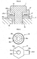
- Fig. 12 illustrates an eighth embodiment of the present invention.
- the washer is comprised of a first washer 21 and a second washer 20.
- the washer 21 is formed by, for instance, stamping a metallic plate and includes a flat plate portion 21e, a claw portion 21a projecting in an outer radial direction from an edge portion of the flat plate portion 21e, a hole 21b formed in the center of the flat plate portion 21e, and a projecting portion 21c projecting downward from an inner edge of the hole 21b.
- the flat plate portion 21e is of hexagonal shape and its linear edge forms an engaging portion to engage with a suitable tool.
- Engaging teeth 21a1 are formed at the tip of the claw portion 21a.
- the trunk 1b of the bolt 1 is pierced through the hole 21b.
- the washer 20 is formed by, for instance, stamping a metallic plate and comprises a flat plate portion 20e, engaging teeth 20b provided on an edge of the flat plate portion 20e, a hexagonal concave fitting portion 20a provided in the center of an upper surface of the flat plate portion 20e, and a hole 20c provided in the center of the fitting portion 20a.
- the head portion 1a of the bolt 1 is fitted into the fitting portion 20a and the trunk 1b of the bolt 1 is pierced through the hole 20c.
- the washer 21 is disposed on the upper surface of the member 2 to be tightened and its projecting portion 21c is inserted into a clearance formed between the trunk 1b of the bolt 1 and the piercing hole 2a of the member 2 to be tightened.
- the washer 20 is disposed on an upper surface of the washer 21. After tightening of the bolt 1, the claw portion 21a of the washer 21 is folded back for engaging its engaging teeth 21a1 with the engaging teeth 20b of the washer 20. In this manner, the washer 20 and the washer 21 are integrated so that they may not be relatively rotated for accordingly preventing loosening of the bolt 1.
- a screw may be passed through the claw portion 21a and the same screw may be screwed into the flat plate portion 21a for preventing deformation through returning of the claw portion 21a after the folding.
- the structure for preventing loosening according to the present embodiment is also applicable to the nut side of a screw-fastening tool as shown in Fig. 4 or 6 (a screw-fastening tool arranged to tighten members to be tightened together through a set of a bolt and a nut). The remaining matters apply correspondingly to the first and the fifth embodiment.
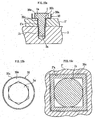
- Figs. 14 and 15 illustrate a ninth embodiment of the present invention.
- Fig. 14 illustrates a condition after completion of tightening and
- Fig. 15 a condition at the time of tightening.
- the trunk 1b of the bolt 1 pierces through a noncircular piercing hole 2'a of a member 2' to be tightened and is screwed into the screw hole 3a of the member 3 to be tightened.
- a washer 30 is interposed between the bearing surface of the head portion 1a of the bolt 1 and an upper surface of the member 2'to be tightened.
- the washer 30 is formed upon stamping, for instance, a metallic plate and comprises a circular flat plate portion 30e, a rising portion 30a rising upward from an edge of the flat plate portion 30e, a noncircular hole 30b formed in the center of the flat plate portion 5e, and a noncircular cylindrical projecting portion 30c projecting downward from an inner edge of the hole 30d.
- all of the piercing hole 2'a of the member 2'to be tightened, the hole 30b and the projecting portion 30c of the washer 30 are formed to be of square shape.
- the projecting portion 30c of the washer 30 is inserted into a clearance formed between the trunk 1b of the bolt 1 and the piercing hole 2'a of the member 2' to be tightened.
- the flat plate portion 30e of the washer 30 is interposed between the bearing surface of the head portion 1a of the bolt 1 and the upper surface of the member 2' to be tightened.
- the projecting portion 30c of the washer 30 is inserted into a clearance formed between the trunk 1b of the bolt 1 and the piercing hole 2'a of the member 2' to be tightened.
- the rising portion 30a of the washer 30 is lower than a height of the head portion 1a of the bolt 1 and is located so as not to interfere the head portion 1a.
- the bolt 1 may still be relatively rotated with respect to the washer 30 in this condition.
- Tightening of the members 2' and 3 to be tightened is performed in the following manner.
- the hole 30b of the washer 30 is first put against the piercing hole 2'a of the member 2' to be tightened (the projecting portion 5c is inserted into the piercing hole 2'a) whereupon the trunk 1b of the bolt 1 is passed through the hole 30b of the washer 30 and the piercing hole 2'a of the member 2' to be tightened to be screwed at the screw hole 3a of the member 3 to be tightened.
- the bolt 1 is then rotated into the tightening direction for screwing a screw portion of the trunk 1b into the screw hole 3a of the member 3 to be tightened and accordingly tightening the members 2' and 3 to be tightened together. Since the bolt 1 and the washer 30 may be relatively rotated in this condition, the bolt 1 rotates without being restrained by the washer 30. Thus, tightening may be performed just like with an ordinary bolt.
- the rising portion 30a of the washer 30 is swaged as shown in Fig. 14 and the swaged portion 30a1 is engaged with an outer periphery of the head portion 1a of the bolt 1.
- the bolt 1 and the washer 5 are integrated such that they cannot be relatively rotated.
- rotation of the washer 30 with respect to the member 2' to be tightened is prevented through the square cylindrical projecting portion 30c of the washer 30 engaging with the square piercing hole 2'a of the member 2' to be tightened in a rotating direction. Loosening of the bolt 1 is accordingly prevented through the washer 30.
- the shape of the projecting portion 30c of the washer 30 and that of the piercing hole 2'a of the member 2' to be tightened is not limited to a square shape but may be of any noncircular shape that may be engaged at least in a direction of loosening the bolt.
- Alternative means for preventing relative rotation between the bolt 1 and the washer 30 may be the structure as illustrated in the third embodiment employing a screw or the structures as illustrated in any one of the fifth to eighth embodiments employing first and second washers.
- the structure for preventing loosening according to the present embodiment is also applicable to the nut side of a screw-threaded fastener as shown in Fig. 4 or 6 (a fastener arranged to tighten members to be tightened together through a set of a bolt and a nut).
Landscapes
- Engineering & Computer Science (AREA)
- General Engineering & Computer Science (AREA)
- Mechanical Engineering (AREA)
- Bolts, Nuts, And Washers (AREA)
Claims (4)
- Konstruktion oder Baugruppe zur Verhinderung des Lockems eines Befestigungselementes mit Gewinde, die aufweist: ein erstes Element (2), das ein Durchgangsloch (2a) umfasst; ein zweites Element (3), das ein Gewindeloch (3a) umfasst; und eine Schraube (1), die einen Kopfabschnitt (1a) und einen Schaft oder Schaftabschnitt (1b) umfasst, wobei das erste Element (2) und das zweite Element (3) miteinander festgezogen werden, indem der Schaft (1b) der Schraube (1) durch das Durchgangsloch (2a) des ersten Elementes (2) eingesetzt, die gleiche in das Gewindeloch (3a) des zweiten Elementes (3) geschraubt und die Schraube (1) angezogen wird;
dadurch gekennzeichnet, dass eine Unterlegscheibe (5) zwischen dem Kopfabschnitt (1a) der Schraube (1) und dem ersten Element (2) angeordnet wird, wobei die Unterlegscheibe (5) einen vorstehenden Abschnitt (5c) umfasst, der in einem Zwischenraum eingesetzt wird, der zwischen dem Schaft (1b) der Schraube (1) und dem Durchgangsloch (2a) des ersten Elementes (2) gebildet wird, wobei eine Höhe (h) des vorstehenden Abschnittes (5c) größer ist als eine Hälfte einer Differenz zwischen dem Durchmesser des Schaftes (1b) der Schraube (1) und dem Durchmesser des Durchgangsloches (2a) des ersten Elementes (2) und kleiner ist als die Differenz, wobei die Schraube (1) und die Unterlegscheibe (5) während des Anziehens der Schraube nicht vereint werden, so dass sie sich relativ drehen können, während die Schraube (1) und die Unterlegscheibe (5) nach dem Festziehen der Schraube (1) vereint sind, so dass sie sich nicht relativ drehen können und daher verhindert wird, dass sich die Schraube (1) lockert. - Konstruktion zur Verhinderung des Lockems eines Befestigungselementes mit Gewinde nach Anspruch 1, die eine zweite Unterlegscheibe (8) aufweist, die zwischen dem Kopfabschnitt (1a) der Schraube (1) und dem ersten Element (2) angeordnet ist, wobei die zweite Unterlegscheibe (8) einen Passabschnitt (8a) umfasst, der zum Kopfabschnitt (1a) der Schraube (1) passt, wobei sich die erste (5) und die zweite Unterlegscheibe (8) während des Anziehens der Schraube (1) relativ drehen, und wobei sich die erste (5) und die zweite Unterlegscheibe (8) nicht in einer Richtung des Lockems der Schraube (1) nach dem Anziehen der Schraube (1) relativ drehen.
- Konstruktion zur Verhinderung des Lockems eines Befestigungselementes mit Gewinde, die aufweist: eine Vielzahl von Elementen (12, 13), die Durchgangslöcher (12a, 13a) umfassen; eine Schraube (1), die einen Kopfabschnitt (1a) und einen Schaft (1b) umfasst; und eine Mutter (6), wobei der Schaft (1b) der Schraube (1) durch die Durchgangslöcher (12a, 13a) der Vielzahl von Elementen (12, 13) vor dem Schrauben der gleichen auf die Mutter (6) für das Anziehen der Mutter (6) geführt wird, um die Vielzahl der Elemente (12, 13) miteinander festzuziehen;
dadurch gekennzeichnet, dass eine Unterlegscheibe (5) zwischen der Mutter (6) und den Elementen (12, 13) angeordnet wird, wobei die Unterlegscheibe (5) einen vorstehenden Abschnitt (5c) umfasst, der in einem Zwischenraum eingesetzt wird, der zwischen dem Schaft (1b) der Schraube (1) und den Durchgangslöchern (12a,13a) der Elemente (12, 13) gebildet wird, wobei eine Höhe (h) des vorstehenden Abschnittes (5c) größer ist als eine Hälfte einer Differenz zwischen dem Durchmesser des Schaftes (1b) der Schraube (1) und dem Durchmesser des Durchgangsloches (12a) des ersten Elementes (12) und kleiner ist als die Differenz, wobei die Mutter (6) und die Unterlegscheibe (5) während des Anziehens der Mutter (6) nicht vereint werden, so dass sie sich relativ drehen können, während die Mutter (6) und die Unterlegscheibe (5) nach dem Festziehen der Mutter (6) vereint sind, so dass sie sich nicht relativ drehen können und daher verhindert wird, dass sich die Mutter (6) lockert. - Konstruktion zur Verhinderung des Lockems eines Befestigungselementes mit Gewinde nach Anspruch 3, die eine zweite Unterlegscheibe (8) aufweist, die zwischen der Mutter (6) und den Durchgangslöcher (12a, 13a) der Elemente (12, 13) angeordnet ist, wobei die zweite Unterlegscheibe (8) einen Passabschnitt (8a) umfasst, der zur Mutter (6) passt, wobei sich die erste (5) und die zweite Unterlegscheibe (8) während des Anziehens der Mutter relativ drehen, und wobei sich die erste (5) und die zweite Unterlegscheibe (8) nicht in einer Richtung des Lockems der Mutter (6) nach dem Anziehen der Mutter (6) relativ drehen.
Applications Claiming Priority (5)
| Application Number | Priority Date | Filing Date | Title |
|---|---|---|---|
| JP2000186970 | 2000-05-19 | ||
| JP2000186970 | 2000-05-19 | ||
| JP2000165447 | 2000-06-02 | ||
| JP2000165447 | 2000-06-02 | ||
| PCT/JP2001/004220 WO2001088391A1 (en) | 2000-05-19 | 2001-05-21 | Structure for preventing loosening of threaded fasteners |
Publications (3)
| Publication Number | Publication Date |
|---|---|
| EP1283373A1 EP1283373A1 (de) | 2003-02-12 |
| EP1283373A4 EP1283373A4 (de) | 2003-07-09 |
| EP1283373B1 true EP1283373B1 (de) | 2007-01-24 |
Family
ID=26593200
Family Applications (1)
| Application Number | Title | Priority Date | Filing Date |
|---|---|---|---|
| EP01932163A Expired - Lifetime EP1283373B1 (de) | 2000-05-19 | 2001-05-21 | Struktur gegen das lösen von befestigungsteilen mit gewinde |
Country Status (7)
| Country | Link |
|---|---|
| US (1) | US6758646B1 (de) |
| EP (1) | EP1283373B1 (de) |
| JP (1) | JP4260398B2 (de) |
| CN (1) | CN1211589C (de) |
| AU (1) | AU5878601A (de) |
| CA (1) | CA2375212A1 (de) |
| WO (1) | WO2001088391A1 (de) |
Families Citing this family (41)
| Publication number | Priority date | Publication date | Assignee | Title |
|---|---|---|---|---|
| US7008158B2 (en) * | 2004-02-05 | 2006-03-07 | Madden Iii James William | Bolt or nut locking fastener and fastening system |
| US20070223994A1 (en) * | 2004-09-13 | 2007-09-27 | Murray Cohen | Integrated locking device |
| US7300237B2 (en) * | 2004-11-22 | 2007-11-27 | Inventio Ag | Self-locking bolted fastener |
| JP4817129B2 (ja) | 2005-06-06 | 2011-11-16 | 日本原子力発電株式会社 | 弁駆動装置 |
| EP1762401B1 (de) * | 2005-09-07 | 2009-04-22 | Aktiebolaget SKF | Verbesserte Bolzenfestlegung für die Lagerung eines Rads auf einer Radnabe |
| CN100368882C (zh) * | 2006-04-14 | 2008-02-13 | 友达光电股份有限公司 | 支撑架与其垫片 |
| JP5060067B2 (ja) * | 2006-06-21 | 2012-10-31 | アーキヤマデ株式会社 | 防水シート固定構造 |
| JP5285899B2 (ja) * | 2007-12-18 | 2013-09-11 | 株式会社不二工機 | 四方切換弁用ピストン装置 |
| WO2010122645A1 (ja) * | 2009-04-22 | 2010-10-28 | Yamada Toru | ボルト用座金 |
| CN102278358A (zh) * | 2011-06-13 | 2011-12-14 | 人和光伏科技有限公司 | 螺纹连接装置 |
| MY181646A (en) * | 2012-09-21 | 2020-12-30 | Mauser Werke Gmbh | Pallet container |
| CN102927111A (zh) * | 2012-11-20 | 2013-02-13 | 无锡创明传动工程有限公司 | 一种螺纹连接副的防松结构 |
| US10336421B2 (en) * | 2012-12-27 | 2019-07-02 | Max Prop S.R.L. | Propeller and relative method for fine adjusting the fluid dynamic pitch of the propeller blades |
| EP2974883B1 (de) * | 2013-03-12 | 2023-07-12 | NTN Corporation | Radlagervorrichtung |
| US9909608B2 (en) * | 2013-08-01 | 2018-03-06 | NejiLaw inc. | Structure for preventing reverse rotation of threaded body |
| WO2015060425A1 (ja) * | 2013-10-25 | 2015-04-30 | 株式会社NejiLaw | ねじ体の逆回転防止構造 |
| CN111075826A (zh) * | 2013-12-17 | 2020-04-28 | 凯特克分部尤尼克斯公司 | 反作用垫圈及其紧固套管 |
| KR101500263B1 (ko) * | 2014-02-27 | 2015-03-06 | 반기수 | 풀림방지용 볼트와 너트의 체결구조 |
| KR101617801B1 (ko) * | 2014-10-16 | 2016-05-03 | 현대모비스 주식회사 | 승객식별장치 |
| DE102015107126A1 (de) * | 2015-05-07 | 2016-11-10 | Knorr-Bremse Systeme für Nutzfahrzeuge GmbH | Vorrichtung und Anordnung zur Verriegelung von schraubbaren Elementen |
| JP2017106603A (ja) * | 2015-12-11 | 2017-06-15 | 有限会社神明山荘 | 締結構造 |
| CN105508390A (zh) * | 2016-01-18 | 2016-04-20 | 杭州斯泰新材料技术有限公司 | 一种紧固机构 |
| DE102016106152A1 (de) * | 2016-04-05 | 2017-10-05 | Elringklinger Ag | Befestigungsvorrichtung für eine Entkopplungsvorrichtung an einem Abschirmteil, Entkopplungsvorrichtung aufweisend die Befestigungsvorrichtung sowie Abschirmteil aufweisend die Entkopplungsvorrichtung |
| CN105952763A (zh) * | 2016-07-20 | 2016-09-21 | 苏州福莱盈电子有限公司 | 一种电路板止转固定组件 |
| CN105952764A (zh) * | 2016-07-20 | 2016-09-21 | 苏州福莱盈电子有限公司 | 一种防脱固定组件 |
| CN106524037A (zh) * | 2016-11-24 | 2017-03-22 | 武汉通畅汽车电子照明有限公司 | 安装孔加强挡圈、车灯安装装置、车灯总成及汽车 |
| JP6934161B2 (ja) * | 2017-02-24 | 2021-09-15 | ボルトエンジニア株式会社 | 締結構造 |
| CN106917809B (zh) * | 2017-04-19 | 2023-11-03 | 贵州轮胎股份有限公司 | 一种防止螺栓松动的装置 |
| KR101973094B1 (ko) * | 2017-05-16 | 2019-04-26 | 삼성중공업 주식회사 | 풀림 방지 너트 및 이를 포함하는 풀림 방지 너트 세트 |
| JP7023493B2 (ja) * | 2017-12-05 | 2022-02-22 | 株式会社不二工機 | ピストン装置及びそれを備えた流路切換弁 |
| FR3082228B1 (fr) * | 2018-06-08 | 2020-09-11 | Safran Aircraft Engines | Piece de turbomachine comprenant une rondelle cooperant avec un lamage |
| KR102184882B1 (ko) * | 2018-11-19 | 2020-12-01 | (주)파인드몰드 | 자력을 이용한 풀림방지 체결장치 |
| CN110397662A (zh) * | 2019-07-25 | 2019-11-01 | 中航光电科技股份有限公司 | 一种螺母防松复合垫圈 |
| CN111005927B (zh) * | 2019-12-27 | 2022-04-15 | 海能达通信股份有限公司 | 紧固组件及防松件 |
| US12000425B2 (en) * | 2020-03-18 | 2024-06-04 | Raytheon Company | Locking threaded fastener assembly |
| CN111692190B (zh) * | 2020-05-15 | 2021-07-16 | 江苏永昊高强度螺栓有限公司 | 一种防松螺栓结构 |
| EP3981230B1 (de) * | 2020-10-07 | 2024-08-21 | Wox Agri Services Ltd | Unterlegscheibe für zinken |
| CN112160970A (zh) * | 2020-10-28 | 2021-01-01 | 中国航发湖南动力机械研究所 | 螺母周向自锁结构及其安装方法 |
| JP7222555B2 (ja) * | 2020-11-12 | 2023-02-15 | 株式会社峰生 | 締結構造体 |
| CN112431843A (zh) * | 2020-12-24 | 2021-03-02 | 申秀云 | 一种螺钉防松装置 |
| CN114810997A (zh) * | 2022-04-20 | 2022-07-29 | 新奥能源动力科技(上海)有限公司 | 一种锁紧装置及旋转机械设备 |
Family Cites Families (14)
| Publication number | Priority date | Publication date | Assignee | Title |
|---|---|---|---|---|
| US1269059A (en) * | 1917-05-11 | 1918-06-11 | William D Arden | Cap-screw lock. |
| FR490445A (fr) * | 1918-06-17 | 1919-04-22 | Earl Herbert Bechberger | Écrou indesserrable |
| US1467688A (en) * | 1922-02-09 | 1923-09-11 | Sartain Louis Martain | Lock nut |
| US2141701A (en) | 1937-04-01 | 1938-12-27 | Julius V Uherkovich | Nut lock |
| US3156281A (en) * | 1960-11-04 | 1964-11-10 | Robertshaw Controls Co | Fastener assembly with resilient locking retainer |
| JPS52113159U (de) * | 1976-02-24 | 1977-08-27 | ||
| WO1989008791A1 (en) | 1988-03-07 | 1989-09-21 | Eisuke Ishida | Fastener |
| JPH02138511A (ja) | 1988-03-26 | 1990-05-28 | Eisuke Ishida | ボルトの固定方法 |
| US4836708A (en) * | 1988-07-05 | 1989-06-06 | Motorola, Inc. | Self-locking, anti-rotational retaining washer for a "D" shaped shaft |
| JPH0716094Y2 (ja) * | 1989-10-12 | 1995-04-12 | 栄助 石田 | ボルト類の共回り防止装置 |
| JPH0792103B2 (ja) | 1991-01-25 | 1995-10-09 | 栄助 石田 | ボルト類の共回り防止装置 |
| US5080545A (en) * | 1991-01-30 | 1992-01-14 | Hong Kong Disc Lock Company Limited | Lock washer assembly having wedge lock action |
| JPH0791427A (ja) * | 1993-09-27 | 1995-04-04 | Toyoji Hashimoto | 緩み止め付き固着具 |
| JPH1182462A (ja) * | 1997-09-16 | 1999-03-26 | Masaaki Naito | 締結具 |
-
2001
- 2001-05-21 CA CA002375212A patent/CA2375212A1/en not_active Abandoned
- 2001-05-21 EP EP01932163A patent/EP1283373B1/de not_active Expired - Lifetime
- 2001-05-21 CN CNB018012175A patent/CN1211589C/zh not_active Expired - Fee Related
- 2001-05-21 WO PCT/JP2001/004220 patent/WO2001088391A1/ja not_active Ceased
- 2001-05-21 AU AU58786/01A patent/AU5878601A/en not_active Abandoned
- 2001-05-21 US US10/018,949 patent/US6758646B1/en not_active Expired - Fee Related
- 2001-05-21 JP JP2001584751A patent/JP4260398B2/ja not_active Expired - Fee Related
Also Published As
| Publication number | Publication date |
|---|---|
| EP1283373A4 (de) | 2003-07-09 |
| JP4260398B2 (ja) | 2009-04-30 |
| EP1283373A1 (de) | 2003-02-12 |
| US6758646B1 (en) | 2004-07-06 |
| CN1372621A (zh) | 2002-10-02 |
| AU5878601A (en) | 2001-11-26 |
| WO2001088391A1 (en) | 2001-11-22 |
| CA2375212A1 (en) | 2001-11-22 |
| CN1211589C (zh) | 2005-07-20 |
Similar Documents
| Publication | Publication Date | Title |
|---|---|---|
| EP1283373B1 (de) | Struktur gegen das lösen von befestigungsteilen mit gewinde | |
| JPWO2001088391A1 (ja) | 螺締具の緩み防止構造 | |
| CN1457401B (zh) | 防松紧固件 | |
| JP5787350B2 (ja) | 締結構造とそれに使用する反力受け用ワッシャ、及び締結用ソケット | |
| EP3587842B1 (de) | Befestigungsstruktur | |
| US6019556A (en) | Locking fastener assembly | |
| US4267870A (en) | Screw fastener with multi-point wrenching head and locking capabilities | |
| US5302066A (en) | Locking fastener | |
| US6779957B2 (en) | Bolt, method of fastening members with the use of the bolt, and method of releasing fastening | |
| US6619161B1 (en) | Anti-tamper nut | |
| CN110799761B (zh) | 紧固装置 | |
| JP2002195236A (ja) | 緩み止めナット | |
| JP2554969Y2 (ja) | カム座金 | |
| US4429600A (en) | Tamper-proof screw assembly | |
| US7246542B2 (en) | Holding socket for a washer nut | |
| JP3354910B2 (ja) | ナットの脱落防止装置 | |
| JP3155204U (ja) | 偏心ロックナット | |
| EP0230453B1 (de) | Sicherungsbolzen | |
| JPH10131976A (ja) | 回転体固定具 | |
| JP3395780B1 (ja) | 悪戯防止締結部品、及び締結構造 | |
| US6918726B1 (en) | Lock nut having ring lock with lug | |
| JP2001050292A (ja) | 緩み止め機能を備えた軸固定具 | |
| US20020164203A1 (en) | Method of fastening panels using blind fasteners with engageable drive nuts | |
| JPH0645691Y2 (ja) | ねじ部品装置 | |
| JP6016652B2 (ja) | 部材の二段接合方法、及び、該方法に用いる部材一段接合用ナット |
Legal Events
| Date | Code | Title | Description |
|---|---|---|---|
| PUAI | Public reference made under article 153(3) epc to a published international application that has entered the european phase |
Free format text: ORIGINAL CODE: 0009012 |
|
| 17P | Request for examination filed |
Effective date: 20020426 |
|
| AK | Designated contracting states |
Designated state(s): AT BE CH CY DE DK ES FI FR GB GR IE IT LI LU MC NL PT SE TR |
|
| AX | Request for extension of the european patent |
Extension state: AL LT LV MK RO SI |
|
| A4 | Supplementary search report drawn up and despatched |
Effective date: 20030526 |
|
| RIC1 | Information provided on ipc code assigned before grant |
Ipc: 7F 16B 39/24 A Ipc: 7F 16B 39/10 B Ipc: 7F 16B 39/32 B |
|
| RBV | Designated contracting states (corrected) |
Designated state(s): DE FR GB |
|
| 17Q | First examination report despatched |
Effective date: 20050314 |
|
| GRAP | Despatch of communication of intention to grant a patent |
Free format text: ORIGINAL CODE: EPIDOSNIGR1 |
|
| GRAS | Grant fee paid |
Free format text: ORIGINAL CODE: EPIDOSNIGR3 |
|
| GRAA | (expected) grant |
Free format text: ORIGINAL CODE: 0009210 |
|
| AK | Designated contracting states |
Kind code of ref document: B1 Designated state(s): DE FR GB |
|
| REG | Reference to a national code |
Ref country code: GB Ref legal event code: FG4D |
|
| REF | Corresponds to: |
Ref document number: 60126267 Country of ref document: DE Date of ref document: 20070315 Kind code of ref document: P |
|
| EN | Fr: translation not filed | ||
| PLBE | No opposition filed within time limit |
Free format text: ORIGINAL CODE: 0009261 |
|
| STAA | Information on the status of an ep patent application or granted ep patent |
Free format text: STATUS: NO OPPOSITION FILED WITHIN TIME LIMIT |
|
| 26N | No opposition filed |
Effective date: 20071025 |
|
| PG25 | Lapsed in a contracting state [announced via postgrant information from national office to epo] |
Ref country code: DE Free format text: LAPSE BECAUSE OF FAILURE TO SUBMIT A TRANSLATION OF THE DESCRIPTION OR TO PAY THE FEE WITHIN THE PRESCRIBED TIME-LIMIT Effective date: 20070425 |
|
| PG25 | Lapsed in a contracting state [announced via postgrant information from national office to epo] |
Ref country code: FR Free format text: LAPSE BECAUSE OF FAILURE TO SUBMIT A TRANSLATION OF THE DESCRIPTION OR TO PAY THE FEE WITHIN THE PRESCRIBED TIME-LIMIT Effective date: 20070914 |
|
| PG25 | Lapsed in a contracting state [announced via postgrant information from national office to epo] |
Ref country code: FR Free format text: LAPSE BECAUSE OF FAILURE TO SUBMIT A TRANSLATION OF THE DESCRIPTION OR TO PAY THE FEE WITHIN THE PRESCRIBED TIME-LIMIT Effective date: 20070124 |
|
| PGFP | Annual fee paid to national office [announced via postgrant information from national office to epo] |
Ref country code: GB Payment date: 20080521 Year of fee payment: 8 |
|
| GBPC | Gb: european patent ceased through non-payment of renewal fee |
Effective date: 20090521 |
|
| PG25 | Lapsed in a contracting state [announced via postgrant information from national office to epo] |
Ref country code: GB Free format text: LAPSE BECAUSE OF NON-PAYMENT OF DUE FEES Effective date: 20090521 |