EP1284195A2 - Sublimationssystem und -verfahren - Google Patents
Sublimationssystem und -verfahren Download PDFInfo
- Publication number
- EP1284195A2 EP1284195A2 EP02016284A EP02016284A EP1284195A2 EP 1284195 A2 EP1284195 A2 EP 1284195A2 EP 02016284 A EP02016284 A EP 02016284A EP 02016284 A EP02016284 A EP 02016284A EP 1284195 A2 EP1284195 A2 EP 1284195A2
- Authority
- EP
- European Patent Office
- Prior art keywords
- web
- heater
- temperature
- sublimation
- dye
- Prior art date
- Legal status (The legal status is an assumption and is not a legal conclusion. Google has not performed a legal analysis and makes no representation as to the accuracy of the status listed.)
- Granted
Links
- 238000000859 sublimation Methods 0.000 title claims abstract description 107
- 230000008022 sublimation Effects 0.000 title claims abstract description 107
- 238000000034 method Methods 0.000 title claims abstract description 32
- 238000010438 heat treatment Methods 0.000 claims abstract description 19
- 238000007639 printing Methods 0.000 claims description 41
- 230000004044 response Effects 0.000 claims description 13
- 239000000463 material Substances 0.000 claims description 7
- 238000005520 cutting process Methods 0.000 claims description 5
- 239000000975 dye Substances 0.000 description 40
- 239000004744 fabric Substances 0.000 description 13
- 230000008569 process Effects 0.000 description 8
- 230000002093 peripheral effect Effects 0.000 description 3
- 239000007787 solid Substances 0.000 description 3
- 238000013459 approach Methods 0.000 description 2
- 230000000694 effects Effects 0.000 description 2
- 230000006870 function Effects 0.000 description 2
- 239000000758 substrate Substances 0.000 description 2
- 238000005406 washing Methods 0.000 description 2
- XUIMIQQOPSSXEZ-UHFFFAOYSA-N Silicon Chemical compound [Si] XUIMIQQOPSSXEZ-UHFFFAOYSA-N 0.000 description 1
- 239000003990 capacitor Substances 0.000 description 1
- 230000008859 change Effects 0.000 description 1
- 238000004140 cleaning Methods 0.000 description 1
- 239000003086 colorant Substances 0.000 description 1
- 238000010276 construction Methods 0.000 description 1
- 238000005034 decoration Methods 0.000 description 1
- 230000007423 decrease Effects 0.000 description 1
- 230000003247 decreasing effect Effects 0.000 description 1
- 238000010586 diagram Methods 0.000 description 1
- 238000005108 dry cleaning Methods 0.000 description 1
- 238000007641 inkjet printing Methods 0.000 description 1
- 238000001459 lithography Methods 0.000 description 1
- 238000004519 manufacturing process Methods 0.000 description 1
- 239000002184 metal Substances 0.000 description 1
- 238000012544 monitoring process Methods 0.000 description 1
- 238000013021 overheating Methods 0.000 description 1
- 229920003023 plastic Polymers 0.000 description 1
- 230000002035 prolonged effect Effects 0.000 description 1
- 230000005855 radiation Effects 0.000 description 1
- 230000000284 resting effect Effects 0.000 description 1
- 238000007650 screen-printing Methods 0.000 description 1
- 229910052710 silicon Inorganic materials 0.000 description 1
- 239000010703 silicon Substances 0.000 description 1
- 229920002994 synthetic fiber Polymers 0.000 description 1
- 238000007651 thermal printing Methods 0.000 description 1
- 238000012546 transfer Methods 0.000 description 1
- 238000011144 upstream manufacturing Methods 0.000 description 1
- 125000000391 vinyl group Chemical group [H]C([*])=C([H])[H] 0.000 description 1
- 229920002554 vinyl polymer Polymers 0.000 description 1
- 229910052724 xenon Inorganic materials 0.000 description 1
- FHNFHKCVQCLJFQ-UHFFFAOYSA-N xenon atom Chemical compound [Xe] FHNFHKCVQCLJFQ-UHFFFAOYSA-N 0.000 description 1
Images








Classifications
-
- B—PERFORMING OPERATIONS; TRANSPORTING
- B41—PRINTING; LINING MACHINES; TYPEWRITERS; STAMPS
- B41J—TYPEWRITERS; SELECTIVE PRINTING MECHANISMS, i.e. MECHANISMS PRINTING OTHERWISE THAN FROM A FORME; CORRECTION OF TYPOGRAPHICAL ERRORS
- B41J2/00—Typewriters or selective printing mechanisms characterised by the printing or marking process for which they are designed
- B41J2/315—Typewriters or selective printing mechanisms characterised by the printing or marking process for which they are designed characterised by selective application of heat to a heat sensitive printing or impression-transfer material
- B41J2/32—Typewriters or selective printing mechanisms characterised by the printing or marking process for which they are designed characterised by selective application of heat to a heat sensitive printing or impression-transfer material using thermal heads
Definitions
- This invention relates to a printing system and, more particularly, the invention relates to a process and apparatus for sublimating at least one sublimable dye on a substrate carrier that may be cut to provide a plurality of labels.
- Sublimation printing basically involves applying a sublimation dye onto a substrate, such as a surface of a fabric.
- a substrate such as a surface of a fabric.
- the fabric is carried through a curing operation in which the fabric is heated to sublime the dye.
- the fabric was typically heated on only one side by feeding the fabric over, for example, an anvil or past a lamp.
- U.S. Patent No. 4,541,340 illustrates another system that uses a Xenon flash lamp to heat a printed side of the web.
- One of the problems with these approaches was that the fabric was not evenly heated.
- Another object of this invention provides a system for sublimating at least one sublimation dye on at least one side of a web, the system comprising a controller for controlling operation of a sublimation station, a heater coupled to the controller and spaced from the web for heating said web to a sublimation temperature to sublimate the at least one sublimation dye, at least one sensor for sensing a web temperature, and the controller energizing the heater in response to the web temperature to maintain the web temperature at substantially the sublimation temperature.
- Still another object of this invention provides a sublimation station comprising a frame, a heater driveably mounted on the frame, the heater comprising a heating area for receiving a web having at least one sublimation dye; the heater being in spaced relation to the web and heating the web to a sublimation temperature to sublimate the at least one sublimation dye, a controller coupled to the heater for controlling operation of the heater, at least one sensor coupled to the controller for sensing a web temperature and generating a web temperature signal in response thereto, and the controller energizing the heater in response to the web temperature signal to maintain the web temperature at substantially the sublimation temperature.
- Yet another object of this invention comprises printing system for printing a plurality of labels, the system comprising a printing station for applying at least one sublimable dye to at least one side of the web, a sublimation station situated downstream of the printing station, the sublimation station comprising a controller for controlling operation of the sublimation station, a heater coupled to the controller and spaced from the web for heating the web to a sublimation temperature to sublimate the at least one sublimable dye on the web, at least one sensor for sensing a web temperature, and the controller energizing the heater in response to the sensed web temperature to maintain the web temperature at substantially the sublimation temperature.
- Still another object of this invention comprises a method for sublimating at least one sublimation dye on a web comprising the steps of moving a heater from a park position to an operating position at which the heater is in spaced relation to the web, sensing a web temperature, and feeding the web through the heater, and energizing the heater to heat the web to a desired sublimation temperature to sublimate the dye.
- Yet another object of this invention comprises a method for printing labels comprising the steps of printing at least one sublimable dye on a web of material as the web moves through a printing station; the sublimable dye defining a plurality of label patterns, sublimating the at least one sublimable dye using a heater in spaced relation to the web of material, the heater being continuously energized to provide sufficient heat to sublimate the at least one sublimable dye, and cutting the web of material to provide a plurality of labels.
- Still another object of this invention comprises a method for printing a plurality of labels comprising at least one sublimation dye, the method comprising the steps of printing at least one sublimation dye on at least one side of a web to define the plurality of labels, driving a heater into operative and spaced relationship with the web, sensing a web temperature with a first sensor and energizing the heater in response to the sensed web temperature in order to maintain the web temperature within a desired sublimation temperature range as the web is fed past the heater.
- Yet another object of this invention comprises a printing system comprising a printer for printing at least one sublimation dye on a web as the web is fed through the printer, a sublimation station for subliming and diffusing the at least one sublimation dye on the web as it moves through the sublimation station, the sublimation station comprising a frame, a heater assembly driveably mounted on the frame and moveable between a park position and an operating position during which the heater assembly is spaced from the web and may heat the web; the heater assembly being energized continuously while in the operating position, a drive motor for driving the heater assembly between the park and operating positions, a sensor for sensing a temperature of the web as the web is being fed through the heater assembly and generating a sensed temperature signal in response thereto, a controller for controlling operation of the printer and the sublimation station, the controller energizing the drive motor to drive the heater assembly between the park position and the operating position and controlling the heater assembly to maintain the web within a sublimation temperature range in response to the sensed temperature as the web
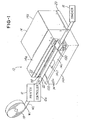
- Fig. 1 is a perspective view of a printing and sublimating system in accordance with one embodiment of the invention, showing a heater in a home or park position;
- Fig. 2 is perspective view, similar to the view shown Fig. 1, showing the heater in an operating or extended position;
- Fig. 3 is a fragmentary view showing various components of the internal components of the sublimation station
- Fig. 4 is an exploded perspective view showing various components of the heater
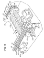
- Fig. 5 is a fragmentary view showing further details of the components shown in Fig. 3 with all heater covers removed;
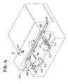
- Fig. 6 is a perspective phantom view illustrating various details of the sensors used in the sublimation station
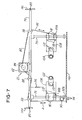
- Fig. 7 is fragmentary plan view illustrating various details of the sensors and drive system
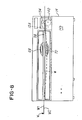
- Fig. 8 is a front view of the sublimation station illustrated in Fig. 3;
- Fig. 9 is an exploded view illustrating the various components of the sensing system shown in Fig. 7;
- Fig. 10 is an exploded perspective view showing details of a feed drive assembly
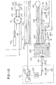
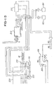
- Fig. 11 is a view showing the layout of the circuit illustrated in Figs. 11A - 11D;
- Figs. 11A - 11D is a circuit diagram of a control system used in the embodiment being described;
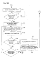
- Figs. 12A - 12D are flow charts of a process or routine for controlling the heater temperature and position
- Fig. 13 is another flow chart view illustrating a process or routine for controlling the heater temperature during operation of the sublimation station
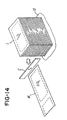
- Fig. 14 is a fragmentary perspective view illustrating a plurality labels made in accordance with the system and methods described herein.
- a label manufacturing system 10 for printing on one or both sides, W1 and W2, of a web W.
- the web W can be composed of fabric, such as is used to make garment labels and the like, or can be composed of paper, synthetic material, such as vinyl or plastic, or other materials.
- the system 10 comprises a printer 12 for printing or applying at least one sublimable dye on one or both sides W1 and W2; a sublimation station 14 for causing at least one dye in the web W to sublime or vaporize and diffuse into the web W; and a stacker 16 for cutting and stacking a plurality of labels L (Fig. 14) after the web W has been printed, sublimed and cut by a cutter C.
- the printer 12 may be a Paxar Model No. 636® printer available from Paxar Corporation of White Plains, NY, the assignee of this application.
- the stacker 16 may be the Paxar SS Finisher, also available from Paxar Corporation of White Plains, NY.
- the printer 12 comprises a control system or controller 12a that is coupled to both the sublimation station 14 and stacker 16.
- the controller 12a controls the operation of the entire system 10, as will be described in detail later herein.
- the printer controller 12a controls the system 10 to cause the web W to be drawn from the supply roll 18 and the printer 12 prints on one or both sides W1 or W2 with at least one sublimable dye determined by the color or colors desired to appear on the finished label.
- the web W is then fed through the sublimation station 14 which sublimates or vaporizes the at least one sublimable dye to fix it into the web W. Thereafter, the web W is cut by the cutter C (Fig. 14) into the plurality of labels L (Fig. 14) and stacked by the stacker 16.
- the sublimation station 14 comprises a housing 20 comprising a heating system or a heater 22 which can be driven from a rest or home position, illustrated in Fig. 1, to an extended or heating position, illustrated in Figs. 2 and 3.
- the heating system or heater 22 comprises at least one first lamp 24 comprising a first pair of lamp bulbs 68 (Fig. 5) and at least one second lamp 26 comprising a second pair of bulbs 70.
- the first and second lamps 24 and 26 are opposed and face sides W1 and W2, respectively, when the web W is being fed through heater 22.
- the first and second lamps 24 and 26 are substantially identical and comprise lamp covers 24a and 26a, respectively.
- a sensor or thermostat 34 (Fig. 4) is mounted to cover 24a with screws 36.
- the sensor 34 is coupled to a sublimation station 14 control circuit or controller 38 (Figs. 3 and 11A) that controls the operation of the sublimation station 14.
- the sensor 34 (Figs. 3 and 4) terminates power to the lamps 24 and 26 if the temperature within the housing 14 generated by the heater 22 exceeds normal operating temperature.
- a plurality of mount guards 40 are secured to covers 24a and 26a with screws 42 and washers 44 as shown.
- the mount guards or mounting blocks 40 maintain the pairs of bulbs 68 and 70 (Fig. 5) spaced from covers 24a and 26a.
- Terminal blocks 48 are mounted to a back panel 25 with screws 50.
- the covers 24a and 26a and back panel 25 are an integral one-piece construction formed of sheet metal.
- the terminal blocks 48 provide terminals for various electrical components mentioned later herein.
- the lamps 24 and 26 of heater 22 provide sufficient energy to heat the web W to the temperature required to sublimate the dyes.
- the heater 22 further comprises bulb covers 52 and 54 (Fig. 4) that are mounted to lamp covers 24a and 26a, respectively, with screws 56 that pass through apertures 58 into mounting blocks 40.
- the lamp cover 24a comprises a sensor bracket 28 mounted to cover 24a with screw 30 that passes through washer 32.
- the bracket 28 comprises a flag in the form of an aperture 28a.
- the aperture 28a cooperates with a heater 22 position sensor 60 (Figs. 2 and 3) that is mounted to a bracket 61 that is in turn mounted to an underside 14a1 of a top surface 14a of the housing 14.
- the sensor 60 senses the presence or absence of the aperture 28a and generates a signal indicating when the heater 22 is in or out of, respectively, the operating or heating position (illustrated in Fig. 2).
- the lamps 24 and 26 comprise front panels or covers 24b and 26b, respectively, that are mounted to the covers 24a and 26a with screws 62 as shown.
- a first pair of lamp bracket mounts 63a and 63b are mounted to cover 52 with screws 64 threadably received in brackets 63a and 63b.
- a pair of second lamp bracket mounts 63c and 63d are mounted to cover 54 with screws 66 that are threadably received in mounts 63c and 63d.
- the lamp bracket mounts 63a and 63b cooperate to receive the lamps bulbs 68
- the lamp bracket mounts 63c and 63d cooperate to receive the lamps bulbs 70, respectively.
- the embodiment being described is shown with two pairs of lamp bulbs 68 and 70, more or fewer bulbs may be used if desired.
- the at least one first and second lamps 24 and 26 are coupled to a silicon controlled rectifier (SCR) controller 204 (Figs. 3 and 11B).
- SCR silicon controlled rectifier
- a programmable pyrometer or controller 104 (Fig. 3) is connected to temperature controller 72 for controlling the actual temperature of the web W (Fig. 3) via its connection to SCR controller 204.
- the control loop from lamps 24 and 26 to web W controls the actual temperature of the web W to permit dye sublimation to occur. If the web W temperature is below the desired temperature, the pyrometer 104 notifies the temperature controller 72 which in turn notifies the SCR controller 204 (Fig. 11B). In response, the SCR controller 204 will increase the energy to the lamps 24 and 26 to increase the temperature of the heater 22. If the web W temperature is too high the opposite occurs.
- Another programmable pyrometer 102 (Fig. 3) is connected to temperature controller 74 for the purpose of monitoring the temperature of the web W to stop the heater 22 if the temperature of the web W falls below a minimum required temperature.
- the sublimation temperature and the desired range at which the sublimation dyes on the web W will be sublimated will vary depending on such things as the type of labels being manufactured and the sublimation dyes being used.
- the heater 22 and lamps 24 and 26 are moved substantially simultaneously in the direction of double-arrow A (Fig. 5) between the park position and the operating position.
- the system 14 comprises heater drive system 23 that will now be described relative to Figs. 5-9.
- the drive system 23 (Fig. 7) comprises a support bracket 76 that is mounted between walls 14c and 14d (Figs. 6 and 7) with screws 85.
- a pair of carriage shafts 78 and 79 (Figs. 6, 7 and 9) are received in linear bearing mounts or blocks 80 and 81.
- the bearing blocks 80 and 81 are mounted to and cover 26a (Fig. 4) with screws 83 that pass through washers 130 and apertures 26a1 of cover 26a.
- the bearing blocks 80 and 81 further comprise a raised shoulder or projection 80a and 81a, respectively. These projections are received in slots 100 (Fig. 1) of surface 14c of housing 14 to permit the mounts 80 and 81 to support the heater 22 and travel in the slots 100 between the park and operating positions mentioned earlier herein.
- Fig. 7 is a top view of the drive assembly with the heater 22 removed from the bearing blocks 80 and 81 for ease of illustration.
- the bearing blocks 80 and 81 (Figs. 7 and 9) are coupled to a drive motor 82 with a drive cable 86 and enable the heater 22 to be driven in the direction of double-arrow A in Fig. 5.
- the drive motor 82 comprises a capstan 84 mounted on a drive shaft (not shown).
- a plurality of pulley wheels 88 are mounted on the bracket 76 as shown.
- a pulley wheel 90 is mounted on a bracket 92 (Fig. 5) that has an end 92a mounted to a front panel 14b (Figs. 1 and 7) of housing 20 with screws 94.
- the ends 86a and 86b of cable 86 are fastened to at least one of the respective bearing mounts 80 as shown.
- the system 14 comprises a spring 96 (Fig. 6), which resiliently biases the bearing blocks 80 and 81 and, consequently, heater 22 in the park or retracted position (illustrated in Fig. 1), such as when power to the drive motor 82 is terminated.
- the heater drive motor 82 is energized to wind the drive cable 86 on capstan 84 which in turn causes the bearing blocks 80 and 81 to move away from bracket 76 (as viewed in Fig. 7) until the heater 22 is in the extended or heating position shown in Figs. 2 and 3.
- the heater 22 defines a generally elongate receiving area or slot 98 (Figs. 1, 2, 3 and 8), which receives the web W when the heater 22 is in the heating position illustrated in Fig. 2.
- the web W is tensioned in the manner described later so that it is situated substantially equidistant between the pairs of bulbs 68 and 70 as illustrated. This facilitates heating both sides W1 and W2 of the web W substantially evenly.
- Fig. 9 illustrates further details of the drive assembly for driving the heater 22.
- Bushings 116 are received on shafts 78 and 79 and positioned between bearing blocks 80 and 81 and bracket 76.
- Pulley wheel 88 is secured to bracket 76 with a cap screw 118 which secures a pulley shaft 122 having a bushing 124 and the pulley wheel 88 mounted thereon.
- a snap ring 126 secures the pulley wheel 88 to the pulley shaft 122.
- the system 10 comprises a sensing system or means for controlling the output of the lamps 24 and 26 and, consequently, the web W temperature.
- the system 10 comprises at least one first sensor 102 coupled to the controller 74 mentioned earlier and at least one second sensor 104 coupled to controller 72, as shown in Figs. 3 - 7 and 9.
- the sensors 102 and 104 are secured to the brackets 106 and 108, respectively, with screws 110 and 112 (Fig. 7), and brackets 106 and 108 are secured to the bearing blocks 80 and 81 with screws 113 and 115 as shown.
- the sensors 102 and 104 are aimed at the aperture 14c1 of surface 14c (Figs. 1 and 2) and aperture 27 (Fig. 3) of lamp cover 26a to capture or sense the temperature of the heater 22 and web W as described later.
- bushings 117 are also situated on shaft 78 to separate the front wall 14b (Fig. 7) of housing 14 from the bearing mounts 80.
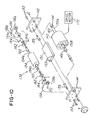
- Figs. 3, 5 and 10 illustrate a feed assembly 138 for feeding web W through the station 14.
- the feed or drive assembly 138 comprises a driven roll 140 situated between a first mounting plate 142 and a second mounting plate 144.
- the driven roll 140 comprises a shaft 150 having a first end 150a and a second end 150b which are received in the bushings 146 and 148, respectively.
- a bracket base plate 151 is mounted between the first and second brackets 142 and 144 and connected to the plate 151 with screws 153 are threadably received in threaded holes, such as holes 155 in the plate 151.
- the feed assembly 138 further comprises a roller 154 that cooperates with driven roll 140 to drive or feed web W through sublimation station 14.
- the roller 154 comprises a first end shaft 154a and a second end shaft 154b that are rotatably received in a first aperture 156a and a second aperture 158a, respectively, of the L-shaped members 156 and 158.
- the L-shaped members 156 and 158 each comprise a bolt 160 that receives a washer 162 and springs 164 that secures the L-shaped members 156 and 158 to the brackets 142 and 144, respectively.
- the springs 164 comprise a bent end 164a received in aperture 156b in arm 156 and an end 164b that engages screw 159.
- the springs 164 resiliently bias the roll 154 against the driven roll 140, as shown in phantom in Fig. 8.
- the feed assembly 138 comprises a jam sensor 168, which senses the presence or absence of the web W, as well as if the web W is jammed. As will be described in detail later herein, if the web W is not present, the sensor 168 generates a signal ultimately received by the printer controller 12a so that the sublimation system 14 will not start, or if it has previously started, the system 10 will respond by retracting the heater 22 to the park position shown in Fig. 1. Also, if the web W should break during operation, the sensor 168 will sense this condition and also cause the heater 22 to be retracted. The process of operating the sensors 34, 60, 102, 104, 108 and 168 will be described in more detail later herein relative to Figs. 11A - 11 D.
- the feed assembly 138 further comprises a feed motor 170 (Figs. 3 and 10) that is operatively coupled by at least one belt and pulley (not shown) to the driven roll 140 to drive the roll 140 to feed the web W from the printer 12, through the sublimation station 14, and to a subsequent operation, such as a cutting and stacking operation.
- a feed motor 170 Figs. 3 and 10
- the driven roll 140 to drive the roll 140 to feed the web W from the printer 12, through the sublimation station 14, and to a subsequent operation, such as a cutting and stacking operation.
- the system 14 comprises an air filter assembly 171 comprising a pair of vent hoses 174 and 175 that open to a pair of brackets 178 and 180, respectively.
- a pair of exhaust fans 182 and 184 exhaust air from the elongate area 98 (Fig. 3) through at least one filter 186 and 188, respectively.
- a pair of filter caps or shrouds 190 and 192 comprise a plurality of detents 190a and 192a for securing the at least one filters 186 and 188 to the exhaust fans 182 and 184 as shown.
- the filter shrouds 190 and 192 are removably secured to the exhaust fans 182 and 184 to permit removal or replacement of the filters 186 and 188, respectively, as needed.
- the exhaust fans 182 and 184 are vented through a pair of apertures (not shown) on a back wall 14d (Figs. 1 and 3) of system 14.
- the controller/control circuit 38 comprises a conventional AC entry terminal 220 which is coupled to a circuit breaker 202 which in turn is coupled to the SCR controller 204 via conventional terminal blocks 206.
- the SCR controller 204 is coupled to bulbs 68 and 70 through terminal blocks 48 and the thermostat 34 mentioned earlier herein.
- the terminal blocks 206 are further coupled to a power supply 210 which provides as its output a 24-volt DC voltage for powering various components, such as the fans 182 and 184.
- the relay 212 is also coupled to a seven-pin conventional microplug 214 which is coupled to stacker 16 as shown.
- the feed motor 170 is powered off lines 216 and 218 and is controlled by a rheostat 220 for controlling and setting the speed at which the motor 170 drives the web W through the sublimation station 14.
- Controller 204 comprises a pair of input terminals 204a and 204b that receive input from controller 72 which in turn is coupled to sensor 104.
- the controller 72 provides control input to controller 204 for controlling the power provided to lamps 68 and 70 during normal sublimation operation.
- the sensor 102 is coupled to solid state relay 226 through controller 74.
- sensor 102 detects the temperature of the web W when the heater 22 is in the heating or operating position (Figs. 2 and 3) and a temperature of the heater 22 when the heater 22 is in the park position (Fig. 1).
- Both sensors 102 and 104 are infrared sensors that sense infrared radiation through aperture 14c1 (Figs. 1 and 2).
- controller 72 transmits a signal via lines 222 and 224 to a normally closed solid state relay 226.
- the relay 226 opens the normally closed gate 227 to generate an "OUT-OF-RANGE" signal on line 228 that is received by printer controller 12a via stacker 16.
- the sublimation station 14 includes the seven-pin receptacle 230 which is coupled to stacker 16.
- the line 228 is coupled to the line (not shown) of stacker 16 so that when relay 226 provides the "OUT-OF-RANGE" signal on line 228, the printer 12 receives the signal and responds in the same manner as when a "STACKER FULL" signal is received. Namely, the printer 12 immediately terminates power to the web feed motor 82 and motor 170. This causes the web W to stop moving through the printer 12. With power to motor 82 terminated, the spring 96 (Fig. 7) retracts the heater 22 to the home position shown in Fig. 1. It should be appreciated that the sublimation station 14 is attached and controlled by the printer controller 12a.
- the printer controller 12a has a standard peripheral interface 240 and is capable of supplying approximately 1.5 amps of current on line 241.
- the "OUT-OF-RANGE" signal is an input from control circuit 38 to printer controller 12a and functions similar to a conventional "STACKER FULL" signal.
- the printer controller 12a receives this signal, the printer 12 will stop printing if it is already printing or will ignore operator requests to start printing if the printer 12 is idle.
- the printer 12 will generate and display an error message as long as the signal is asserted on line 228.
- This line 228 is pulled up to a logic high within the printer 12 and any peripheral attached to the printer 12 can assert an error condition or notice by pulling this line 228 down to a logic low. This allows multiple peripherals such as the sublimation station 14 and the stacker 16, to be attached to and signal the printer controller 12a by asserting or using this line 228.
- the line 228 is connected to printer 12 via receptacle 230.
- the printer controller 12a is coupled to the heater 22 drive motor 82 via a bipolar stepper motor drive channel 46.
- the circuit 38 further comprises a sensor channel comprising a standard optocoupler interface 250.
- the printer 12 comprises a pair of resistors, labeled R1 and R2 in Fig. 11C, which are coupled to lines 241 and 243, as shown.
- Line 241 is also connected to an analog-to-digital converter 252 for converting analog signal on line 241 to a digital signal for use by the printer controller 12a.
- Circuit 38 comprises a resistor R3 that is coupled to a phototransistor 254.
- a light emitting diode (LED) 256 is situated in opposed relation to the transistor 254 to provide the sensor 60 (Fig. 3).
- the sensor 168 (Fig. 11 D) comprises the phototransistor 258 and opposed LED 260.
- the LED 260 is coupled to a fourth resistor R4 (Fig. 11 D) which is coupled to a fifth resistor R5 and a sixth resistor R6 and a power supply 210 as shown.
- the circuit 38 further comprises a resistor R7 and capacitor C1 which are coupled in series and connected to line 245.
- the printer controller 12a may determine the type of sublimation system to which it is coupled by applying a current on line 262 and monitor the change in the voltage state to determine whether the sublimation station 14 which is coupled to the printer 12 is of the type shown and described herein or of a predecessor model, such as Paxar Model No. 636® Lokprint, available from Paxar Corporation of White Plains, NY.
- An electronically erasable programmable read only memory (EEPROM) 262 is also coupled to line 245, but is non-functional in the embodiment being described. Also, a plurality of fuses F1, F2 and F3 may be provided to protect the controller 38 from overload. The operation of the controller 38 and printer controller 12a will now be described.
- EEPROM electronically erasable programmable read only memory
- the sensors 102 and 104 monitor the temperature of the web W or the temperature of the heater 22.
- Sensor 104 operates independent of the sensor 102, which monitors the temperature of the web W at start up and the temperature of the heater 22 when the heater is in the home or park position.
- the heater 22 is driven to the operating position illustrated in Figs. 2 and 3.
- the printer controller 12a terminates power to motor 82, whereupon spring 96 causes the heater 22 to retract to the home position (Fig. 1). This facilitates preventing the heater 22 from overheating or burning the web W.
- the sensor 102 senses the temperature of the heater 22 to determine if the heater 22 temperature is at the desired temperature set in controller 72.
- the output of the sensor 102 is coupled via controller 74 and solid state relay 226 to line 229 of the connector 230 mentioned earlier herein. If the temperature sensed by sensor 102 is outside the desired range, then controller 72 causes the relay 226 to generate the "OUT-OF-RANGE" signal on line 22 that functions like a conventional "STACKER FULL" signal mentioned earlier herein.
- the printer controller 12a receives this signal and stops the printing operation and simultaneously terminates power to motor 170. This causes the web W to cease moving through sublimation station 14. Substantially simultaneously, the printer controller 12a ceases energizing stepper motor 82, and spring 96 (Figs. 6 and 7) causes the heater station 22 to retract to the home or park position illustrated in Fig. 1.
- the system 14 comprises a mechanical switch 280 which senses when the heater 22 is in the fully retracted position illustrated in Fig. 1 or in the extended position illustrated in Fig. 2.
- the switch 280 is used to switch the temperature controller between two predetermined set points depending on the position of the heater 22. If the heater 22 is in the park or home position illustrated in Fig. 1, then switch 280 is inactive and causes the SCR controller 204 to pass current to lamps 68 and 70 until they achieve a resting set point temperature. This enables the lamps 68 and 70 to remain energized while the heater 22 is in the rest or park position to avoid prolonged startup times when the printer 12 is first started. If, on the other hand, the heater 22 is in the operating position illustrated in Figs.
- the switch 280 is activated or closed and SCR controller 204 provides more power to lamps 68 and 70 to increase the temperature output of the heater 22.
- the switch 280 and SCR controller 204 cooperate to control the output of lamps 68 and 70 until the web W temperature reaches the set point temperature.
- the web sensor 168 comprises the photodiode 260 which cooperates with the phototransistor 258 to sense the presence or absence of the web W as it moves through the sublimation station 14.
- the web W will block the light from photodiode 260, thereby indicating the presence of the web W. If the light from the photodiode 260 is received by phototransistor 258, the phototransistor 258 is turned on, thereby indicating that the web W is not in its proper position.
- the output of the sensor 168 is combined with the output of sensor 60 which operates in a similar manner except that the sensor 60 utilizes the arm of sensor bracket 28 and the aperture 28a to sense when the heater 22 is in the operating position (Figs. 2 and 3), in which case the aperture 28a permits the LED 256 to energize the phototransistor 254.
- the bracket 28 blocks the LED 256 light when not in the operating position.
- the output of the sensor 60 is combined with the output of the sensor 168 and this output is provided via line 241 (Fig. 11C) to the analog-to-digital converter 252 (Fig. 11C) which in turn provides three distinct states that are represented by three distinct voltage levels as follows: STATE VOLTAGE LEVEL HEATER 22 POSITION WEB W PRESENT? 1 >4 VOLTS PARK EITHER 2 >2.5 VOLTS, ⁇ 4 VOLTS OPERATING NO 3 ⁇ 2.5 VOLTS OPERATION YES
- the thermostat 34 (Figs. 4 and 11B) is attached as described earlier herein and will interrupt the power provided by SCR controller 204 to the lamps 68 and 70 if the thermostats temperature rating is exceeded.
- the thermostat 34 is selected to have a temperature rating higher than the operating end of the operating sublimation temperature range.
- the web W is supplied from a supply roll 18 (Fig. 1) to printer 12 and an operator threads it to the nip 194 (Fig. 3) between rollers 140 and 154.
- the operator may initially manually rotate the knob 155 (Fig. 3) to tension the web W.
- the operator powers the printer 12 and the sublimation station 14 at which time the web W is brought up to the sublimation temperature and the printer 12 may begin applying the at least one sublimation or sublimable dye is applied to either or both the first side W1 or second side W2 of the web W.
- the feed assembly 138 feeds the web through the nip 194 between driven roll 140 and roller 154. As best illustrated in Fig.
- the printer 12 and station 14 are in the idle state as indicated at Block 300 in Fig. 12A.
- the routine proceeds to decision block 302 where sensor 102 senses the temperature of the heater 22 in the rest position.
- decision block 304 it is determined whether the temperature has achieved the park or home temperature set point programmed by the user into controller 72. If it has not, the printer controller 12a indicates an error on a printer user interface (not shown) at block 306 and thereafter loops back to the printer idle state at block 300.
- any previous error indicator is turned off at block 308. If the operator has not requested to start printing, then the routine loops back to the printer idle state at block 300 as shown. After an operator requests to start printing, the routine proceeds to reset a first step counter (not shown) in printer controller 12a and a second step counter (not shown) in printer controller 12a at block 312. The routine proceeds to block 314 where a temperature timer and web drive timer in printer controller 12a are also reset.
- a web tightening process may be initiated and a web drive timer (block 317 in Fig. 12B) is started. Next, it is determined whether the web drive timer has exceeded two seconds at decision block 318. If it has not, then the routine loops back as shown. If the web drive timer has met or exceeded two seconds, thereby indicating that the web drive motor 170 has been energized for at least two seconds, then the web W is properly tensioned and the routine proceeds to block 319 where the drive motor 170 is de-energized.
- the routine proceeds to block 320 where the printer controller 12a begins energizing the stepper motor 82 (Figs. 7, and 11) to move the heater 22 toward the operating position illustrated in Figs. 2 and 3.
- the first step counter is incremented and the routine determines at decision block 324 whether the counter has exceeded a maximum count, which corresponds to an error condition, such as, if the heater 22 feed motor 82 is jammed. If it has not, then it is determined whether the heater 22 is in the proper position at decision block 326 and if it is not then the routine loops backs to block 320 as shown.
- the routine proceeds to turn the printer error indicator on at block 328. Thereafter, the routine proceeds to block 330 and printer controller 12a removes power from the heater 22 drive motor 82 and the spring 96 (Fig. 7) returns the heater 22 to the rest or home position illustrated in Fig. 1. The routine then returns to the printer idle condition at block 300 in Fig. 12A.
- the routine proceeds to block 332 and printer controller 12a energizes drive motor 82 to step the heater 22 toward the operating position shown in Figs. 2 and 3.
- the second counter is incremented and the routine proceeds to determine whether the second counter equals ten, which corresponds to the number of counts necessary to get the sensor 60 centered in aperture 28a. It should be appreciated that the step count may be higher or lower depending on the characteristics of the aperture 28a or stepper motor 82. If the second counter is not equal to ten, then the heater 22 is not in the proper operating position to heat the web W, and the routine loops back to block 332 as shown.
- bracket 28 should be aligned in sensor 60 to permit the diode 256 (Fig. 11) to energize the phototransistor 254 and the sensor 60 should be relatively insensitive to vibration.
- the printer controller 12a starts the temperature timer TT (not shown) at block 340. It should be appreciated that when the heater 22 is in the operating position illustrated in Fig. 2, the manual switch 280 (Figs. 3 and 11 B) is activated so that the SCR controller 204 (Fig. 11 B) sets the temperature setting to the operating temperature set point. Thereafter, the routine proceeds to block 348 (Fig. 12D) where sensor 102 senses a temperature of the web W within the area 98 of the heater 22. At block 350, it is determined whether the web W is at the proper temperature to sublimate the dye which has been printed on one or even both sides W1 and W2 of printer 12.
- the routine determines (block 352) whether the temperature timer TT is greater than or equal to five seconds, which corresponds to the maximum time required for lamps 68 and 70 to bring the web W up to the proper sublimation temperature mentioned earlier herein. If the temperature timer TT has not achieved at least five seconds, then the routine loops back to block 350. On the other hand, if the temperature timer TT has achieved at least five seconds while the web W is not at the proper temperature to sublimate the at least one sublimation dye, the routine proceeds to block 342 where an error indicator on the printer 12 is again initiated and stepper motor 82 is de-energized and spring 96 returns heater 22 to the home position.
- the routine proceeds to block 354 where the printer 12 begins applying the at least one sublimation dye to at least one or both of the sides W1 and W2 of the web W. Thereafter, the web drive motor 170 (decision block 356) is energized to pull the web W through the printer 12 and sublimation station 14. During this time, the sublimation station 14 continuously monitors the temperature of the web W using sensor 102 to ensure that the web W is at a proper temperature to sublimate the at least one sublimation dye. Thus, if it is determined at decision block 358 (Fig.
- the routine proceeds to indicate an error indicator or message on the printer 12 when it returns to block 342 (Fig. 12C) as shown. If the web W is at the proper sublimation temperature, the web W is present and in the proper position, and the heater 22 is in the print position (illustrated in Figs. 2 and 3), then printing is performed. The web W is passed to the stacker 16 where web W is cut by cutter C (Fig. 14) to provide the plurality of labels L. It is then determined whether printing is complete (decision block 356). If it is not, the routine continues to monitor the web temperature and returns to decision block 358.
- the routine returns to block 344 (Fig. 12C) where the web drive motor 170 is de-energized and power from the heater drive motor 82 is terminated (block 346). As mentioned earlier, this enables spring 96 (Fig. 7) to return heater 22 to the park position. If the web W is at the proper temperature to sublimate the at least one sublimation dye as determined at decision block 358, but the web W is not present or in the proper position in the heater 22 or the heater 22 is not in the print position, then the routine again generates an error indicator or message and returns to block 342 (Fig. 12C).
- Fig. 13 wherein it is determined at decision block 364 whether heater 22 is in the park position illustrated in Fig. 1. If it is not, then SCR controller 204 (Fig. 11D) sets the temperature set point for the desired operating or web temperature (block 362) using controller 74. If the decision at decision block 364 is affirmative, then the SCR controller 204 sets a heater 22 temperature set point for a desired heater 22 temperature (block 368). As mentioned earlier, the heater 22 temperature is the operating temperature of the lamps 68 and 70 while in the park position.
- the sensor 104 senses the temperature of the web W and controller 72 (Fig. 11A) determines (block 372) in Fig. 13 whether the temperature exceeds the desired set point temperature. If it does not, then SCR controller 204 increases the lamp intensity (block 374). If the web temperature equals or exceeds the desired set point temperature, then the controller 204 (Fig. 11B) decreases power to the lamps 68 and 70 to lower the lamp intensity (block 376). After increasing or decreasing the lamp intensity at blocks 374 and 376 the routine loops back to decision block 364 as shown.
- this system and method provides means for controlling the position of the heater 22 and the temperature generated by the heater 22 so that a web temperature of the web W will be maintained at substantially the desired sublimation temperature or within a desired sublimation temperature range.
- This system and method further facilitate bringing the web temperature up to the desired sublimation temperature or within the sublimation temperature range before the web W moves through the sublimation station 14.
- the sublimable dye will be sublimated approximately midway through the heater 22. It has been found that the additional time that the web W is exposed to the lamps 68 and 70 of heater 22 as the web W travels from midway through the lamps to the end 22f facilitates ensuring that the at least one sublimable dye that is printed on one or both sides of web W has been properly sublimated.
Landscapes
- Electronic Switches (AREA)
- Lining Or Joining Of Plastics Or The Like (AREA)
Applications Claiming Priority (2)
| Application Number | Priority Date | Filing Date | Title |
|---|---|---|---|
| US09/927,482 US6698958B2 (en) | 2001-08-10 | 2001-08-10 | Sublimation system and method |
| US927482 | 2001-08-10 |
Publications (3)
| Publication Number | Publication Date |
|---|---|
| EP1284195A2 true EP1284195A2 (de) | 2003-02-19 |
| EP1284195A3 EP1284195A3 (de) | 2003-10-22 |
| EP1284195B1 EP1284195B1 (de) | 2006-11-29 |
Family
ID=25454798
Family Applications (1)
| Application Number | Title | Priority Date | Filing Date |
|---|---|---|---|
| EP02016284A Expired - Lifetime EP1284195B1 (de) | 2001-08-10 | 2002-07-23 | Sublimationssystem und -verfahren |
Country Status (3)
| Country | Link |
|---|---|
| US (1) | US6698958B2 (de) |
| EP (1) | EP1284195B1 (de) |
| DE (1) | DE60216377T2 (de) |
Families Citing this family (9)
| Publication number | Priority date | Publication date | Assignee | Title |
|---|---|---|---|---|
| US7213866B2 (en) * | 2004-06-25 | 2007-05-08 | Metts Iv Carey Gregory | Soft top for vehicles |
| US7431807B2 (en) * | 2005-01-07 | 2008-10-07 | Universal Display Corporation | Evaporation method using infrared guiding heater |
| US8870972B2 (en) * | 2005-03-02 | 2014-10-28 | Airdye Intellectual Property, Llc | Sublimation dying of textiles and other materials |
| US20080050517A1 (en) * | 2006-08-23 | 2008-02-28 | Colorep, Inc. | Pulse Heating Methods and Apparatus for Printing and Dyeing |
| RU2546490C2 (ru) | 2010-01-28 | 2015-04-10 | Авери Деннисон Корпорейшн | Системы и процессы нанесения термотрансферных этикеток |
| BR122014017821A2 (pt) | 2010-01-28 | 2019-07-09 | Avery Dennison Corporation | Sistema para aplicação de rótulos em artigos |
| US20140129184A1 (en) | 2012-11-08 | 2014-05-08 | Avery Dennison Corporation | Systems, Methods, and Media for Labeling Three Dimensional Surfaces |
| US9352588B1 (en) | 2015-04-02 | 2016-05-31 | Ricoh Company, Ltd. | Adjustable energy source within a drum dryer of a print system |
| WO2023049104A1 (en) | 2021-09-27 | 2023-03-30 | Sekisui Kydex, Llc | Systems and methods of pyrometric temperature measurement and control in dye sublimation |
Citations (6)
| Publication number | Priority date | Publication date | Assignee | Title |
|---|---|---|---|---|
| US4541640A (en) | 1982-01-29 | 1985-09-17 | Westinghouse Brake And Signal Co. | Piston sealing arrangement |
| US4640191A (en) | 1985-08-13 | 1987-02-03 | Bradley Gerald R | Sublimation printing apparatus |
| US4776714A (en) | 1986-07-15 | 1988-10-11 | Monarch Marking Systems, Inc. | Ink ribbon cassette with movable guide rolls |
| US5015324A (en) | 1988-06-22 | 1991-05-14 | Monarch Marking Systems, Inc. | Hand-held labeler |
| US5150130A (en) | 1989-12-14 | 1992-09-22 | Kabushiki Kaisha Shinsei Industries | Label printer |
| US5961228A (en) | 1997-08-22 | 1999-10-05 | Paxar Corporation | Modular printer |
Family Cites Families (20)
| Publication number | Priority date | Publication date | Assignee | Title |
|---|---|---|---|---|
| GB1376108A (en) * | 1970-11-12 | 1974-12-04 | Glover R D | Method of sublimatic printing on sheet structures |
| US3966396A (en) * | 1974-12-18 | 1976-06-29 | F P Licensing Co Inc | Textile printing process and transfer medium |
| FR2447819A1 (fr) * | 1979-01-30 | 1980-08-29 | Essilor Int | Procede et dispositif pour la decoration d'un quelconque substrat, en particulier monture de lunettes |
| US4541340A (en) | 1982-07-02 | 1985-09-17 | Markem Corporation | Process for forming permanent images using carrier supported inks containing sublimable dyes |
| JPH0632965B2 (ja) * | 1985-04-25 | 1994-05-02 | ロ−ム株式会社 | 多色転写型プリンタ |
| JPH0232861A (ja) * | 1988-07-22 | 1990-02-02 | Eastman Kodatsuku Japan Kk | 昇華型サーマルプリンタ |
| JP2918118B2 (ja) * | 1989-09-04 | 1999-07-12 | 新日本製鐵株式会社 | 捺染プリント装置 |
| JPH06191102A (ja) * | 1992-12-24 | 1994-07-12 | Tokyo Electric Co Ltd | プリンタ |
| US5721581A (en) * | 1993-11-30 | 1998-02-24 | Canon Kabushiki Kaisha | Recording apparatus |
| JP3252064B2 (ja) * | 1994-10-17 | 2002-01-28 | 富士写真フイルム株式会社 | サーマルプリンタ |
| JP2928137B2 (ja) * | 1995-06-29 | 1999-08-03 | 石川県 | 乾式連続染色方法及び装置 |
| JP3533779B2 (ja) * | 1995-10-04 | 2004-05-31 | カシオ計算機株式会社 | カラー印刷装置 |
| JP3352879B2 (ja) | 1995-11-10 | 2002-12-03 | 松下電器産業株式会社 | 画像記録装置、画像データ記録方法およびレンチキュラーシート |
| US5746521A (en) * | 1996-12-20 | 1998-05-05 | Intermec Corporation | Thermal printhead with integrated printhead position sensor |
| EP0860287B1 (de) * | 1997-02-05 | 2001-07-18 | Fuji Photo Film Co., Ltd. | Direkt thermisch aufzeichender Drucker, direkt thermisch aufzeichendes Druckverfahren und Transportvorrichtung für Aufzeichnungsmaterial |
| US6078344A (en) * | 1997-09-11 | 2000-06-20 | Eastman Kodak Company | Resistive thermal printing apparatus and method having a non-contact heater |
| JP3674824B2 (ja) * | 1997-12-27 | 2005-07-27 | 株式会社リコー | 印字・消去方法 |
| WO1999051442A1 (en) | 1998-04-06 | 1999-10-14 | Fargo Electronics, Inc. | Card printer and laminator with shared power supply |
| US6425926B1 (en) * | 1999-05-04 | 2002-07-30 | Jakobus Hindriks | Thermosol treatment of textiles carrying a dye |
| US6206589B1 (en) * | 1999-09-24 | 2001-03-27 | Fargo Electronics, Inc. | Printer ribbon compensation |
-
2001
- 2001-08-10 US US09/927,482 patent/US6698958B2/en not_active Expired - Lifetime
-
2002
- 2002-07-23 DE DE60216377T patent/DE60216377T2/de not_active Expired - Lifetime
- 2002-07-23 EP EP02016284A patent/EP1284195B1/de not_active Expired - Lifetime
Patent Citations (6)
| Publication number | Priority date | Publication date | Assignee | Title |
|---|---|---|---|---|
| US4541640A (en) | 1982-01-29 | 1985-09-17 | Westinghouse Brake And Signal Co. | Piston sealing arrangement |
| US4640191A (en) | 1985-08-13 | 1987-02-03 | Bradley Gerald R | Sublimation printing apparatus |
| US4776714A (en) | 1986-07-15 | 1988-10-11 | Monarch Marking Systems, Inc. | Ink ribbon cassette with movable guide rolls |
| US5015324A (en) | 1988-06-22 | 1991-05-14 | Monarch Marking Systems, Inc. | Hand-held labeler |
| US5150130A (en) | 1989-12-14 | 1992-09-22 | Kabushiki Kaisha Shinsei Industries | Label printer |
| US5961228A (en) | 1997-08-22 | 1999-10-05 | Paxar Corporation | Modular printer |
Also Published As
| Publication number | Publication date |
|---|---|
| US20030035675A1 (en) | 2003-02-20 |
| US6698958B2 (en) | 2004-03-02 |
| DE60216377D1 (de) | 2007-01-11 |
| DE60216377T2 (de) | 2007-03-15 |
| EP1284195B1 (de) | 2006-11-29 |
| EP1284195A3 (de) | 2003-10-22 |
Similar Documents
| Publication | Publication Date | Title |
|---|---|---|
| EP1284195B1 (de) | Sublimationssystem und -verfahren | |
| CA1213138A (en) | Catalytic fixer-dryer for liquid developed electrophotocopiers | |
| EP0867301B1 (de) | Tintenstrahlaufzeichnungsgerät und Fixier-Heizelement für solch ein Gerät | |
| US6832831B2 (en) | Image forming apparatus | |
| US5249255A (en) | Resin curing apparatus and method utilizing infrared lamp and blower control means | |
| EP1508451B1 (de) | Digitale Textildruckmaschine | |
| EP0710569A1 (de) | Papierendedetektor | |
| JPH07164678A (ja) | バーコードプリンタ用自動プリント速度制御装置 | |
| KR20070104273A (ko) | 주전원의 과부하를 방지하는 가변 속도 인쇄 장치 | |
| WO1993013951A1 (en) | Transfer unit for printing systems | |
| EP1090771B1 (de) | Flüssige Tinte verwendender Drucker mit einer nicht verbrennenden Trockeneinheit | |
| JPH0148149B2 (de) | ||
| JP2006265813A (ja) | 布地への画像形成方法及び装置 | |
| WO1992005031A1 (en) | Method and apparatus for drying liquid media | |
| US7510276B2 (en) | Temperature control system for a sheet support plate of a printer | |
| US4912486A (en) | Sublimation type thermal printer | |
| AU701787B2 (en) | Ink temperature control | |
| JP4070441B2 (ja) | プリンター装置および加熱ユニット | |
| US20060143940A1 (en) | System and method for curing and heat-setting a resin dye in a material | |
| US5851345A (en) | Heat transfer recording sheet producing apparatus and a roll shaft supplying apparatus | |
| JP2673422B2 (ja) | ラべリングマシン | |
| JP2505633Y2 (ja) | 自動スクリ―ン捺染機の加熱装置 | |
| CN207510006U (zh) | 一种在墙纸印刷中用到的自动送料及收卷设备 | |
| JP2010181859A (ja) | 画像形成装置 | |
| JPH07214813A (ja) | サーマルプリンタ |
Legal Events
| Date | Code | Title | Description |
|---|---|---|---|
| PUAI | Public reference made under article 153(3) epc to a published international application that has entered the european phase |
Free format text: ORIGINAL CODE: 0009012 |
|
| AK | Designated contracting states |
Designated state(s): AT BE BG CH CY CZ DE DK EE ES FI FR GB GR IE IT LI LU MC NL PT SE SK TR |
|
| AX | Request for extension of the european patent |
Extension state: AL LT LV MK RO SI |
|
| PUAL | Search report despatched |
Free format text: ORIGINAL CODE: 0009013 |
|
| AK | Designated contracting states |
Kind code of ref document: A3 Designated state(s): AT BE BG CH CY CZ DE DK EE ES FI FR GB GR IE IT LI LU MC NL PT SE SK TR |
|
| AX | Request for extension of the european patent |
Extension state: AL LT LV MK RO SI |
|
| RIC1 | Information provided on ipc code assigned before grant |
Ipc: 7B 41J 3/407 A |
|
| 17P | Request for examination filed |
Effective date: 20040322 |
|
| AKX | Designation fees paid |
Designated state(s): DE FR GB IT NL |
|
| 17Q | First examination report despatched |
Effective date: 20050221 |
|
| GRAP | Despatch of communication of intention to grant a patent |
Free format text: ORIGINAL CODE: EPIDOSNIGR1 |
|
| GRAS | Grant fee paid |
Free format text: ORIGINAL CODE: EPIDOSNIGR3 |
|
| GRAA | (expected) grant |
Free format text: ORIGINAL CODE: 0009210 |
|
| AK | Designated contracting states |
Kind code of ref document: B1 Designated state(s): DE FR GB IT NL |
|
| REG | Reference to a national code |
Ref country code: GB Ref legal event code: FG4D |
|
| REF | Corresponds to: |
Ref document number: 60216377 Country of ref document: DE Date of ref document: 20070111 Kind code of ref document: P |
|
| ET | Fr: translation filed | ||
| PLBE | No opposition filed within time limit |
Free format text: ORIGINAL CODE: 0009261 |
|
| STAA | Information on the status of an ep patent application or granted ep patent |
Free format text: STATUS: NO OPPOSITION FILED WITHIN TIME LIMIT |
|
| 26N | No opposition filed |
Effective date: 20070830 |
|
| REG | Reference to a national code |
Ref country code: FR Ref legal event code: PLFP Year of fee payment: 15 |
|
| REG | Reference to a national code |
Ref country code: FR Ref legal event code: PLFP Year of fee payment: 16 |
|
| REG | Reference to a national code |
Ref country code: FR Ref legal event code: PLFP Year of fee payment: 17 |
|
| PGFP | Annual fee paid to national office [announced via postgrant information from national office to epo] |
Ref country code: NL Payment date: 20180627 Year of fee payment: 17 |
|
| PG25 | Lapsed in a contracting state [announced via postgrant information from national office to epo] |
Ref country code: NL Free format text: LAPSE BECAUSE OF NON-PAYMENT OF DUE FEES Effective date: 20190801 |
|
| REG | Reference to a national code |
Ref country code: NL Ref legal event code: MM Effective date: 20190801 |
|
| PGFP | Annual fee paid to national office [announced via postgrant information from national office to epo] |
Ref country code: FR Payment date: 20210629 Year of fee payment: 20 |
|
| PGFP | Annual fee paid to national office [announced via postgrant information from national office to epo] |
Ref country code: GB Payment date: 20210629 Year of fee payment: 20 |
|
| PGFP | Annual fee paid to national office [announced via postgrant information from national office to epo] |
Ref country code: IT Payment date: 20210719 Year of fee payment: 20 |
|
| PGFP | Annual fee paid to national office [announced via postgrant information from national office to epo] |
Ref country code: DE Payment date: 20210616 Year of fee payment: 20 |
|
| REG | Reference to a national code |
Ref country code: DE Ref legal event code: R071 Ref document number: 60216377 Country of ref document: DE |
|
| REG | Reference to a national code |
Ref country code: DE Ref legal event code: R081 Ref document number: 60216377 Country of ref document: DE Owner name: AVERY DENNISON RETAIL INFORMATION SERVICES LLC, US Free format text: FORMER OWNER: PAXAR CORP., MIAMISBURG, OHIO, US Ref country code: DE Ref legal event code: R082 Ref document number: 60216377 Country of ref document: DE Representative=s name: MUELLER-BORE & PARTNER PATENTANWAELTE PARTG MB, DE |
|
| REG | Reference to a national code |
Ref country code: GB Ref legal event code: PE20 Expiry date: 20220722 |
|
| REG | Reference to a national code |
Ref country code: GB Ref legal event code: 732E Free format text: REGISTERED BETWEEN 20220825 AND 20220831 |
|
| PG25 | Lapsed in a contracting state [announced via postgrant information from national office to epo] |
Ref country code: GB Free format text: LAPSE BECAUSE OF EXPIRATION OF PROTECTION Effective date: 20220722 |