EP1284323B1 - Dispositif de fabrication d'un chemin en béton, ainsi que dispositif associé pour introduire des goujons - Google Patents
Dispositif de fabrication d'un chemin en béton, ainsi que dispositif associé pour introduire des goujons Download PDFInfo
- Publication number
- EP1284323B1 EP1284323B1 EP02078338A EP02078338A EP1284323B1 EP 1284323 B1 EP1284323 B1 EP 1284323B1 EP 02078338 A EP02078338 A EP 02078338A EP 02078338 A EP02078338 A EP 02078338A EP 1284323 B1 EP1284323 B1 EP 1284323B1
- Authority
- EP
- European Patent Office
- Prior art keywords
- concrete
- dowels
- elements
- machine
- insertion elements
- Prior art date
- Legal status (The legal status is an assumption and is not a legal conclusion. Google has not performed a legal analysis and makes no representation as to the accuracy of the status listed.)
- Expired - Lifetime
Links
- 238000003780 insertion Methods 0.000 claims description 65
- 230000037431 insertion Effects 0.000 claims description 65
- 238000007789 sealing Methods 0.000 claims description 18
- 210000003141 lower extremity Anatomy 0.000 claims description 4
- 238000001514 detection method Methods 0.000 claims description 3
- 230000007246 mechanism Effects 0.000 claims description 2
- 210000001364 upper extremity Anatomy 0.000 claims description 2
- 238000000034 method Methods 0.000 abstract description 11
- 238000006073 displacement reaction Methods 0.000 description 4
- 230000008602 contraction Effects 0.000 description 3
- 210000003414 extremity Anatomy 0.000 description 3
- 238000009499 grossing Methods 0.000 description 3
- 230000004913 activation Effects 0.000 description 2
- 238000010276 construction Methods 0.000 description 2
- 230000001105 regulatory effect Effects 0.000 description 2
- 230000002787 reinforcement Effects 0.000 description 2
- 230000000903 blocking effect Effects 0.000 description 1
- 230000000694 effects Effects 0.000 description 1
- 238000002347 injection Methods 0.000 description 1
- 239000007924 injection Substances 0.000 description 1
- 238000005204 segregation Methods 0.000 description 1
Images




Classifications
-
- E—FIXED CONSTRUCTIONS
- E01—CONSTRUCTION OF ROADS, RAILWAYS, OR BRIDGES
- E01C—CONSTRUCTION OF, OR SURFACES FOR, ROADS, SPORTS GROUNDS, OR THE LIKE; MACHINES OR AUXILIARY TOOLS FOR CONSTRUCTION OR REPAIR
- E01C23/00—Auxiliary devices or arrangements for constructing, repairing, reconditioning, or taking-up road or like surfaces
- E01C23/04—Devices for laying inserting or positioning reinforcing elements or dowel bars with or without joint bodies; Removable supports for reinforcing or load transfer elements; Devices, e.g. removable forms, for making essentially horizontal ducts in paving, e.g. for prestressed reinforcements
Definitions
- This invention relates to a machine for forming a concrete path or the like, as well as to a device for inserting dowels which can be applied to this end.
- dowels in concrete paths, usually mostly at the location of joints, more particularly so-called load transfer joints, expansion joints or contraction joints.
- Such dowels are reinforcement bars with a length of approximately 0.5 m, which mostly are provided in the concrete in the longitudinal direction of the path to be formed. Contrary to traditional reinforcement bars, they mostly consist of smooth-surfaced bars used to form a load-transfer joint of expansion or contraction type.
- a whole series of such dowels next to each other is provided at mutual interspaces of, for example, 20 to 50 cm.
- a groove is formed, for example, cut, in the concrete, in order to form the expansion joint.
- the lower part With a possible expansion or contraction, the lower part then forms a breaking zone, whereas the dowels still form a connection between both concrete parts, limiting any vertical movement of the concrete, e.g. caused by load applied by the traffic.
- such dowels are provided in the concrete after having formed the concrete path, when the concrete still is wet.
- a series of dowels is dropped in a controlled manner onto the wet concrete surface, after which these dowels subsequently, by means of vibrating forks, are vibrated into the formed concrete path up to a well-defined depth.
- this is performed by means of a device situated at the paving machine by which the concrete path is realized, which device, during the insertion of the dowels, temporarily is stopped in respect to the concrete path, whereas the actual paving machine travels on, whereby, after the insertion of the dowels, the respective device is drawn forward.
- An important disadvantage consists in that, as the dowels are inserted into the already formed concrete surface, this surface is disturbed, as a result of which an additional finishing operation, mostly by means of a finishing beam also fixed at the paving machine, must be provided for. Even when using such finishing beam, one will note that at the location where the dowels have been inserted, a demixing or so-called segregation of the concrete takes place, resulting in a poor quality of the finally obtained concrete surface.
- Another disadvantage of said known technique consists in that such paving machine is relatively long, as a consequence of which it is difficult to turn and difficult to transport, due to the fact that the device must be able to be stopped temporarily for inserting the dowels, whereas the paving machine travels on, and this device, thus, must be movable in the longitudinal direction of the concrete path, over guide elements, as well as due to the fact that an additional finishing beam is required.
- Another disadvantage of said known technique consists in that one never knows with certainty whether the dowels are situated on the right place in the concrete, as they may come loose from below the vibrating forks during insertion.
- inserting the dowels according to said known technique requires a large power, for commanding and moving the device along the paving machine, as well as for pushing and vibrating the dowels into the concrete.
- the invention aims at a machine and device with which one or more of said disadvantages can be excluded and according to which a concrete path provided with dowels can be realized in a very efficient manner.
- a similar machine is already known from FR 2.164.580 , but the present invention aims at a machine with insertion elements, the first of them serving as a dowel magazine and the second compartment serving as a pressing device that co-operates with the dowel below in the first compartment.
- the invention relates to a machine, more particularly a paving machine, for forming a concrete path, whereby this machine comprises at least one movable frame, at which a form piece for forming the concrete path is attached, as well as a device for inserting dowels, situated in front of and/or at the height of the form piece according to the travel direction of the machine, i.e.
- the device for inserting dowels comprises one or more insertion elements, which are equiped with drive means and which are configured and installed in such a manner that the dowels, during their insertion into the concrete, systematically are enclosed by the concrete according to their longitudinal direction, characterised in that said drive means comprise drive elements situated substantially at the upper side of the insertion elements; and whereby said insertion elements comprise two compartments situated adjacent to each other, the first compartment functioning as a magazine in which the dowels can be stacked horizontally upon each other, and the second compartment offering space for a pressing piece pertaining to the drive means whereby the pressing piece, next to its upper extremity, whether directly or indirectly, is in connection with one or more of the drive elements and which, next to its lower extremity, by means of a passage between the two compartments, can cooperate with a dowel situated below in the first compartment.
- the invention relates also to the device for inserting dowels, which can form a part of and/or can be attached to a paving machine, provided with insertion elements equipped with drive means as in claim 1.
- finishing beam there will be no necessity for using a finishing beam, as a consequence of which the construction of the applied machine can be particularly simple. However, this does not exclude that such finishing beam and/or other finishing elements, such as a smoothing board moving to and fro, can be used.
- the dowels are inserted such into the concrete that, in longitudinal direction, they are systematically enclosed by the concrete, in other words, in respect to the concrete, are inserted or injected in a generally horizontal manner. Due to this manner of insertion, there will be no lateral movement of the dowels through the concrete, which further excludes the occurrence of a certain demixing of the concrete.
- the concrete is vibrated and the dowels are brought into the concrete at the location where the concrete is vibrated.
- the dowels are brought into the concrete at the location where the concrete is vibrated.
- a device with one or more insertion elements for dowels for the insertion of the dowels in the concrete use is made of a device with one or more insertion elements for dowels, and these insertion elements, at least during the periods of time when dowels have to be inserted, are moved, together with the movement of the form piece, through the unhardened concrete which still has to be treated by means of the form piece.
- these insertion elements substantially are situated in front of the form piece, these elements in fact can be permanently pushed through the rather raw concrete without causing any problem, this contrary to the known dowel apparatuses mounted behind the form piece.
- no more means are necessary for blocking the insertion means in the longitudinal direction of the concrete path and to draw them back to the paving machine after an insertion cycle.
- the insertion elements at least at their lower ends, are located at a distance from each other, thereby providing passages for the concrete between these elements.
- An important advantage hereby is that the concrete can be poured in front of the insertion elements, and still better in a traditional manner in front of the complete paving machine. This technique is less critical than in the case that the concrete would be supplied in between the insertion elements and the form piece.
- a device for inserting the dowels which comprises several feeding elements provided next to each other at regular interspaces, in order to bring thereby several dowels next to each other into the concrete, and the concrete is vibrated by means of different vibrating elements which are positioned between the respective insertion elements.
- the dowels for the insertion of the dowels in the concrete, use is made of a device with one or more insertion elements for dowels and are the dowels pushed out of these insertion elements in longitudinal direction and thereby inserted into the concrete. As a consequence thereof, the dowels are put into the concrete in a particularly uniform manner.
- the dowels are inserted by keeping them ready in the insertion elements, in the longitudinal direction of the concrete path, and subsequently, at the moment when they have to be brought into the concrete, releasing them from the insertion elements according to their longitudinal direction. As this takes place according to the longitudinal direction, the surrounding concrete is not disturbed and the risk of demixing is minimized.
- the dowels are kept ready in a centering part and/or sealing part, from where the dowels, through an exit opening, are brought outside one after the other.
- This centering part and/or sealing part preferably is oblong and slim, such that it is easily enclosed by the concrete and subsequently this concrete connects around the released dowels in an efficient manner.
- the dowels are expelled by means of a centering part and/or sealing part; that at a location where a dowel has to be inserted, such dowel is kept ready in the centering part and/or sealing part; that a second dowel is provided behind said dowel, in the prolongation thereof; and that during inserting, the first dowel is pushed outside by the movement of the second, after which the second dowel becomes located in the centering part and/or sealing part, ready for a subsequent cycle.
- This technique offers the advantages that the dowels simply can be brought from the insertion elements to the outside, as well as that no concrete can penetrate into the insertion device, as the place of each inserted dowel immediately is taken by another.
- the dowels are released from the insertion elements by moving them thereoff with a direction of movement in respect to the insertion elements moved through the concrete which is opposed to the direction of movement of the insertion elements, however, with a speed which is equal to, or approximately equal to, the speed of the insertion elements travelling through the concrete.
- a speed which is equal to, or approximately equal to, the speed of the insertion elements travelling through the concrete.
- said preferred characteristic according to which the dowels are inserted at the location where the concrete is vibrated, as well as said preferred characteristic according to which the dowels are inserted such into the concrete that they systematically are surrounded by the concrete in longitudinal direction, form characteristics which minimize the risk of demixing of the concrete, and that they also may be applied apart from the first aspect of the invention, thus, apart from the fact whether the dowels are inserted into the concrete at a location in front of the form piece and/or at the height of the form piece.
- the concrete path is provided with dowels, whereby unhardened concrete, by means of at least one form piece moving over the concrete, is brought into the shape of the concrete path to be realized, whereby the concrete is vibrated and the dowels are inserted into the concrete at the location where the concrete is vibrated.
- dowels are inserted at the location where the concrete is vibrated, in fact a compacting of the concrete around the dowels is created, without having a demixing occurring, regardless whether the insertion now takes places in front, below or behind the form piece.
- the dowels inserted such into the concrete that, in longitudinal direction, they are systematically surrounded by the concrete.
- the machine at least comprises a movable frame, to which a form piece for forming the concrete path is attached, as well as a device for inserting dowels, and, according to the invention, shows the characteristic that the device for inserting dowels is situated, according to the travel direction of the machine, in front of and/or at the height of the form piece.
- the invention also relates to a device for inserting dowels, as well as a paving machine according to the invention.
- a device for inserting dowels as well as a paving machine according to the invention.
- such devices may be constructed as units for separate attachment at a paving machine.
- such device regardless of the fact whether it fixedly belongs to a certain paving machine or not, can be made modular, as a consequence of which it may easily be adapted to different working widths and/or the interspaces between the dowels situated next to each other may easily be adapted. It is also not excluded to realize the device telescopically adjustable according to the working width, for example, by applying a series of insertion units which are suspended at a telescopic frame and which, in function of the span of the telescopic frame, all systematically are suspended farther or less far from each other, whereby possibly certain units, when suspended too close to each other, can be taken out of operation.
- the invention relates to a machine, more particularly a paving machine 1, for forming a concrete path 2 which is provided with dowels 3.
- the paving machine 1 substantially consists of a frame 4, whether or not extensible in width and/or length, and which is movable by means of support elements 5 situated, for example, at the corner points, which elements are provided, for example, with crawler tracks 6 which can be driven by means of motors which are not represented in the figures.
- these tools consist of, respectively, schematically indicated means 7 for spreading concrete 8 poured in front of the paving machine 1, a device 9 for inserting the dowels 3, means 10 for vibrating the concrete, one or more form pieces 11 and a finishing element 12.
- the means 7 may be of different kind and consist, for example, of a plough for spreading the concrete 8 and/or a driven element, such as a worm screw for distributing the concrete 8.
- the means 10 for vibrating the concrete preferably consist of a series of internal vibrators in the shape of a needle, further called vibrating needles 13, which, during the treatment of the concrete 8, reach up into the concrete 8, preferably up to below the form piece 11.
- vibrating needles 13 may consist in a known manner of cylindrical vibration elements in which driven excenter weights are provided, the speed of which preferably can be regulated.
- the form piece 11 substantially consists of a large mould with which the concrete is pressed into a certain shape and simultaneously is given a smooth surface.
- the form piece is made in a straight manner, for example, as a profile with a cross-section, such as represented in figure 1, which extends over the working width. It is clear that it may also have special shapes and may be composed of several parts, for example, for forming a gutter, a standing edge or the like at a concrete path.
- the finishing element 12 consists of a smoothing board which can be moved systematically over the formed surface 14 of the concrete path 2.
- the particularity of the invention consists in that the device 9 for inserting dowels 3, according to the travel direction V of the paving machine 1 during paving, is situated in front of and/or at the height of the form piece 11, contrary to known embodiments whereby the dowel apparatus is mounted behind the form piece.
- the device 9 substantially is composed of, on one hand, a series of insertion elements 15 for dowels 3, positioned adjacent to each other at regular interspaces, and, on the other hand, drive means 16 cooperating therewith.
- the insertion elements 15 are suspended such at the frame 4 that they, during the operation of the machine 1, anyway, at least during the periods of time when dowels 3 have to be brought into the concrete 8, reach up into the concrete 8 situated in front of the form piece 11, more particularly are hanging down into the concrete with their undersides.
- the insertion elements 15 and the vibration elements, more particularly vibrating needles 13, are positioned in an alternating manner adjacent to each other, distributed over the working width, as clearly represented in figure 2.
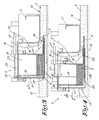
- the insertion elements 15 consist of upwardly directed elements, each with a housing 17 of a small width extending substantially in a vertical plane parallel to the travel direction of the machine 1.
- These insertion elements 15 each comprise two compartments situated adjacent to each other, on one hand, a first compartment 18 functioning as a magazine and in which dowels 3 can be stacked horizontally one upon the other and, on the other hand, a second compartment 19 forming a passage for a pressing mechanism pertaining to the drive means 16, more particularly a pressing piece 20, which pressing piece 20 in fact can be considered as a device for horizontal injection of the dowels.
- the pressing pieces 20 are connected at their uppermost extremity to a transverse profile 22 extending according to the working width of the machine 1, which profile, in its turn, is movable in that it is coupled, as represented in figures 2 to 7, to the piston rods 23, which can be moved in and out, of the pressure cylinders 21.
- the transverse profile 22 can be shifted over guides 24.
- the pressing pieces 20 are provided with a laterally directed cam 25, as a result of which they can cooperate, by means of an open connection, more particularly a passage 26, between the two compartments 18-19, with a dowel 3 situated below in the first compartment 18.
- a centering and sealing part 28 is connected which consists of a relatively slim element, with a through-channel 29 which, on one hand, gives out in the magazine for the dowels 3 and, on the other hand, at its free extremity, forms an outlet opening 30 for the dowels 3.
- This centering and sealing part 28 extends parallel to the movement direction of the paving machine 1 and usually is situated such that the outlet opening 20, viewed according to the thickness of the concrete path 2 to be realized, is situated approximately in the middle thereof, as well as it is situated below the front half of the form piece 11, and still more particularly, at the height of the extremities of the vibrating needles 13.
- the centering and sealing part 28 preferably consists of an exchangeable sleeve in which two support points for the centered holding of the dowels 3, in the form of sealing rings 31-32, are provided. Due to the exchangeability, it is possible to provide sleeves for dowels 3 of different diameters and/or lengths.
- the centering and sealing part 28 preferably extends with such a length behind the rear wall 27 that, during the presence of one dowel 3 in this part 28, still a second dowel 3 from of compartment 18 can be positioned therebehind.
- the device 9 is equipped with a detection device 33 which can cooperate with elements 34, erected next to the paving path, for example, small posts provided especially to this aim, and thereby it can activate the drive means 16.
- each pressing piece 20 is situated with its cam 25 behind the lowermost dowel 3 present in the pertaining magazine.
- the pressing elements 20 then are moved once to and fro, by having the piston rods 23 once go in and back out.
- a condition ready for an operation cycle is created, as illustrated in figure 3, whereby at the bottom, two dowels 3 are situated axially one behind the other, one of which is situated in the centering and sealing part 21, in readiness for being applied.
- concrete 8 is poured in front of the paving machine 1. This concrete 8 first is roughly spread by said means 7, after which, by means of the form piece 11, the actual concrete path 2 is formed. An additional smoothing movement may be performed by means of the finishing element 12.
- the insertion elements 15 are sliding through the concrete 8.
- the pressing elements 20, which originally are in the starting position of figure 3, are subjected to a backward displacement S by having the piston rods 23 go in.
- the activation of the piston rods 23 hereby is, for example, the consequence of a signal delivered by said detection device 33.
- such activation also can be commanded manually by applying an appropriate control signal to the pressure cylinders 21.
- the drawing in of the piston rod 23, and more particularly the displacement of the pressing pieces 20, is performed at a speed which is equal to the travelling speed of the paving machine 1.
- the direction of displacement of the pressing pieces 20 in respect to the insertion elements 15, however, is opposed to the travel direction of the paving machine 1, this results in the fact that the dowels 3 which leave the insertion elements 15 are kept at a standstill in respect to the surroundings, whereas the insertion elements 15 move forward and thereby release the respective dowels 3.
- This speed can be regulated by means of appropriate, not-represented control means.
- the dowels 3, being released and inserted into the concrete 8 are, according to their longitudinal direction, systematically surrounded by the concrete, whereby, also as a result of the effect of the vibrating needles 13, a good compacting of the concrete 8 around the dowels 3 is obtained.
- different parts may be made adjustable, exchangeable and/or modular. So, for example, is it possible to apply adaptable side walls in the compartments 18, as a result of which the length and diameter of the compartments 18 can be adjusted in function of the length of the applied dowels 3. Also the depth at which the insertion elements 15 are hanging in the concrete 8, as well as the location where these insertion elements 15 are attached in the width of machine 1, can be adjustable.
- the dowels preferably are inserted parallel to the travel direction of the paving machine, it is not excluded to realize this at a slight angle of, for example, 15 degrees. To this end, the insertion elements 15 can be adjusted at an angle.
- the magazines can be located quite close to the form piece, which offers several advantages, such as a more stable construction. In a preferred embodiment, this distance is less than the maximum length of the dowel bars for which the magazines have been designed.
Landscapes
- Engineering & Computer Science (AREA)
- Architecture (AREA)
- Civil Engineering (AREA)
- Structural Engineering (AREA)
- Road Paving Machines (AREA)
- On-Site Construction Work That Accompanies The Preparation And Application Of Concrete (AREA)
- Road Paving Structures (AREA)
- Bulkheads Adapted To Foundation Construction (AREA)
- Joining Of Building Structures In Genera (AREA)
Claims (10)
- Machine, plus particulièrement bétonnière, pour réaliser une chaussée en béton (2), ladite machine comprenant au moins un bâti mobile (4) auquel est fixée une pièce de façonnement (11) pour le façonnement de la chaussée en béton (2), ainsi qu'un dispositif pour insérer des goujons (3) situés à l'avant et/ou à hauteur de la pièce de façonnement (11) dans la direction de déplacement de la machine, c'est-à-dire dans la direction de déplacement lors du bétonnage, le dispositif pour insérer des goujons (3) comprenant un ou plusieurs éléments d'insertion (15) qui sont équipés de moyens d'entraînement (16), qui sont configurés et qui sont montés de telle sorte que les goujons (3), lors de leur insertion dans le béton (8), de manière systématique sont enrobés par le béton (8) dans leur direction longitudinale, caractérisée en ce que lesdits moyens d'entraînement (16) comprennent des éléments d'entraînement (21) disposés essentiellement sur le côté supérieur des éléments d'insertion (15) et lesdits éléments d'insertion (15) comprennent deux compartiments (18, 19) situés en position réciproquement adjacente, le premier compartiment (18) faisant office de magasin dans lequel des goujons (3) peuvent être empilés à l'horizontale les uns sur les autres, et le deuxième compartiment (19) procurant un espace pour une pièce de compression (20) faisant partie du dispositif d'entraînement (16), la pièce de compression, à proximité de son extrémité supérieure, que ce soit de manière directe ou indirecte, étant mise en connexion avec un ou plusieurs des éléments d'entraînement (21) et, à proximité de son extrémité inférieure, au moyen d'un passage (26) entre les deux compartiments (18, 19) étant à même de coopérer avec un goujon (3) disposé en dessous dans le premier compartiment (18).
- Machine selon la revendication 1, caractérisée en ce que lesdits un ou plusieurs éléments d'insertion (15) pour des goujons (3) équipés de moyens d'entraînement (16) sont suspendus au bâti (4) de telle sorte que, en état de marche de la machine, et au moins lorsque des goujons (3) doivent être amenés dans le béton (8), s'étendent jusque dans le béton (8) à l'avant de la pièce de façonnement (11) et se déplacent de cette manière à travers le béton (8) qui est déversé à l'avant des éléments d'insertion (15), devant le dispositif, respectivement de manière simultanée avec le mouvement de la machine.
- Machine selon la revendication 1 ou 2, caractérisée en ce que le dispositif comprend plusieurs éléments d'insertion (15) prévus à des espaces intermédiaires réciproques, et comprend également différents éléments vibreurs (13), ces éléments d'insertion (15) et ces éléments vibreurs (13) étant montés en position réciproquement adjacente pour être distribués en alternance sur la largeur de travail.
- Machine selon l'une quelconque des revendications 1 à 3, caractérisée en ce que les éléments d'insertion (15) sont munis d'une partie de centrage et/ou d'une partie d'étanchéité (28) à travers laquelle les goujons (3) peuvent être expulsés à partir des éléments d'insertion (15).
- Machine selon la revendication 4, caractérisée en ce que ladite partie de centrage et/ou ladite partie d'étanchéité manifestent une configuration telle que le goujon peut y être maintenu à l'état prêt ; en ce qu'à l'avant de la partie de centrage et/ou de la partie d'étanchéité (28), dans leur prolongement, un espace est présent dans lequel on peut prévoir un deuxième goujon ; et en ce que les moyens d'entraînement (16) sont réalisés de telle sorte qu'ils peuvent pousser le deuxième goujon en direction axiale dans la partie de centrage et/ou dans la partie d'étanchéité (28), si bien que le premier goujon est expulsé de l'élément d'insertion respectif (15).
- Machine selon l'une quelconque des revendications 1 à 5, caractérisée en ce que lesdits éléments d'insertion (15) sont munis pour les goujons (3) d'une ouverture de sortie (30) orientée vers l'arrière et en ce que les moyens d'entraînement 16 sont munis de moyens de commande qui font en sorte d'amener les goujons (3) hors des ouvertures de sortie (30) vers l'extérieur à une vitesse qui est égale ou approximativement égale à la vitesse du mouvement vers l'avant des éléments d'insertion (15) à travers le béton (8).
- Machine selon l'une quelconque des revendications 1 à 6, caractérisée en ce que les moyens d'entraînement (16) sont constitués essentiellement par un ou plusieurs mécanismes de compression avec lesquels les goujons (3) sont expulsés des éléments d'insertion (15).
- Machine selon l'une quelconque des revendications 1 à 7, caractérisée en ce que les éléments d'insertion (15), y compris les magasins qui en font partie, sont orientés vers le haut et s'étendent essentiellement dans la direction de déplacement de la machine.
- Machine selon l'une quelconque des revendications 1 à 8, caractérisée en ce qu'elle est munie d'un dispositif de détection (33) qui est en mesure de coopérer avec des éléments (34) montés à proximité de la chaussée et par conséquent qui est en mesure d'activer les moyens d'entraînement (16).
- Dispositif pour insérer des goujons, qui peut faire partie d'une bétonnière et/ou qui peut être fixé à une bétonnière, caractérisé en ce qu'il est muni d'éléments d'insertion (15) équipés de moyens d'entraînement (16), ledit dispositif étant tel que défini dans l'une quelconque des revendications 1 à 9.
Applications Claiming Priority (2)
| Application Number | Priority Date | Filing Date | Title |
|---|---|---|---|
| BE2001/0543A BE1014342A3 (nl) | 2001-08-13 | 2001-08-13 | Werkwijze en machine voor het vormen van een betonbaan of dergelijke, alsmede inrichting voor het inbrengen van deuvels hierbij aangewend. |
| BE200100543 | 2001-08-13 |
Publications (2)
| Publication Number | Publication Date |
|---|---|
| EP1284323A1 EP1284323A1 (fr) | 2003-02-19 |
| EP1284323B1 true EP1284323B1 (fr) | 2007-12-05 |
Family
ID=3897080
Family Applications (1)
| Application Number | Title | Priority Date | Filing Date |
|---|---|---|---|
| EP02078338A Expired - Lifetime EP1284323B1 (fr) | 2001-08-13 | 2002-08-12 | Dispositif de fabrication d'un chemin en béton, ainsi que dispositif associé pour introduire des goujons |
Country Status (6)
| Country | Link |
|---|---|
| US (4) | US7037035B2 (fr) |
| EP (1) | EP1284323B1 (fr) |
| AT (1) | ATE380270T1 (fr) |
| BE (1) | BE1014342A3 (fr) |
| DE (1) | DE60223878T2 (fr) |
| ES (1) | ES2296873T3 (fr) |
Families Citing this family (14)
| Publication number | Priority date | Publication date | Assignee | Title |
|---|---|---|---|---|
| BE1016562A3 (nl) | 2005-04-08 | 2007-01-09 | Drion Constructie Bv Met Beper | Verbeterd deuvelapparaat voor betonneermachine en betonneermachine die met zulk deuvelapparaat is uitgerust. |
| US20070239724A1 (en) * | 2005-09-14 | 2007-10-11 | Jorey Ramer | Mobile search services related to direct identifiers |
| US20100086352A1 (en) * | 2008-10-03 | 2010-04-08 | Donny Guilbault | Dowel bar loader |
| CN102392410B (zh) * | 2011-10-17 | 2013-07-03 | 哈尔滨工业大学 | 水泥混凝土路面振动式压填缝一体机 |
| US10648139B2 (en) | 2014-02-13 | 2020-05-12 | Ronald A. Knapp | Carriage suspended concrete drill gang assembly |
| US9873992B1 (en) * | 2014-02-13 | 2018-01-23 | Ronald A. Knapp | Truck mounted concrete drill gang assembly |
| WO2019133915A1 (fr) * | 2017-12-29 | 2019-07-04 | Guntert & Zimmerman Const. Div., Inc. | Dispositif d'insertion de barre de cheville à largeur étendue |
| US11873608B2 (en) * | 2020-06-23 | 2024-01-16 | Power Curbers Companies, LLC | Slipform concrete paving machine having dowel bar inserter mechanism with continuous floor |
| US12203226B2 (en) | 2021-12-20 | 2025-01-21 | Wirtgen Gmbh | Dowel bar inserter |
| US12553196B2 (en) | 2022-12-14 | 2026-02-17 | Wirtgen Gmbh | Measuring paving thickness during slip form paving |
| US12601122B2 (en) | 2022-12-14 | 2026-04-14 | Wirtgen Gmbh | Adjustable string line sensors for slip form paving |
| US12473698B2 (en) | 2022-12-14 | 2025-11-18 | Wirtgen Gmbh | Roll control during slip form paving |
| US12590423B2 (en) | 2023-08-04 | 2026-03-31 | Wirtgen Gmbh | Edge slump control |
| US12584277B2 (en) | 2023-08-04 | 2026-03-24 | Wirtgen Gmbh | Constant surface patterns during slip form paving |
Family Cites Families (15)
| Publication number | Priority date | Publication date | Assignee | Title |
|---|---|---|---|---|
| US3274906A (en) * | 1963-12-09 | 1966-09-27 | Edoco Technical Products | Joint installation apparatus |
| BE793214A (fr) * | 1971-12-23 | 1973-04-16 | Robert Mcgregor & Sons Ltd | Dispositif pour introduire des tiges, des goujons, ou analogues, dans les chaussees a revetement de beton |
| GB1415308A (en) * | 1972-10-11 | 1975-11-26 | Laing & Son Ltd John | Slipform paver |
| US4312602A (en) * | 1979-11-19 | 1982-01-26 | Pav-Saver Mfg. Co. | Wet concrete pavement spreading machine and reinforcing rod layer |
| US4493584A (en) * | 1981-12-17 | 1985-01-15 | Guntert & Zimmerman Const. Div., Inc. | Apparatus and process for dowel insertions |
| FR2570723B2 (fr) * | 1983-11-17 | 1986-12-12 | Gtm Ets Sa | Machine a coffrage glissant a deux plaques d'extrusion pour la confection de chaussees en beton |
| US4688963A (en) * | 1986-04-21 | 1987-08-25 | Rexworks Inc. | Dowel bar placing |
| US5405242A (en) * | 1990-07-09 | 1995-04-11 | United Technologies Corporation | Cooled vane |
| US5135333A (en) * | 1991-01-09 | 1992-08-04 | Guntert & Zimmerman Const. Div. Inc. | Band reinforcement inserting apparatus and process |
| US5209602A (en) * | 1991-06-10 | 1993-05-11 | Gomaco Corporation | Method and apparatus for inserting dowel bars for a concrete slip forming machine |
| US5405212A (en) | 1992-06-18 | 1995-04-11 | Cmi Corporation | Paving machine with drop-then-stop dowel bar insertion |
| AU1832795A (en) * | 1994-01-21 | 1995-08-08 | George W. Swisher Jr. | Paving material machine having a tunnel with automatic gate control |
| US5654227A (en) * | 1996-01-23 | 1997-08-05 | Micron Technology, Inc. | Method for local oxidation of silicon (LOCOS) field isolation |
| BE1011289A3 (nl) * | 1997-07-23 | 1999-07-06 | Casters Francois | Betonneermachine. |
| US6390726B1 (en) * | 1999-10-01 | 2002-05-21 | Guntert & Zimmerman Const. Div. | Dowel bar inserter kit having chain feeder |
-
2001
- 2001-08-13 BE BE2001/0543A patent/BE1014342A3/nl not_active IP Right Cessation
-
2002
- 2002-08-12 EP EP02078338A patent/EP1284323B1/fr not_active Expired - Lifetime
- 2002-08-12 ES ES02078338T patent/ES2296873T3/es not_active Expired - Lifetime
- 2002-08-12 AT AT02078338T patent/ATE380270T1/de active
- 2002-08-12 DE DE60223878T patent/DE60223878T2/de not_active Expired - Lifetime
- 2002-08-13 US US10/216,848 patent/US7037035B2/en not_active Expired - Fee Related
-
2005
- 2005-04-21 US US11/078,315 patent/US7214001B2/en not_active Expired - Fee Related
-
2007
- 2007-03-20 US US11/723,448 patent/US7303355B2/en not_active Expired - Fee Related
- 2007-03-20 US US11/723,451 patent/US20070196172A1/en not_active Abandoned
Also Published As
| Publication number | Publication date |
|---|---|
| DE60223878T2 (de) | 2008-11-13 |
| BE1014342A3 (nl) | 2003-09-02 |
| DE60223878D1 (de) | 2008-01-17 |
| US20070160422A1 (en) | 2007-07-12 |
| ES2296873T3 (es) | 2008-05-01 |
| ATE380270T1 (de) | 2007-12-15 |
| US7214001B2 (en) | 2007-05-08 |
| US20030041556A1 (en) | 2003-03-06 |
| EP1284323A1 (fr) | 2003-02-19 |
| US20070196172A1 (en) | 2007-08-23 |
| US20060104717A1 (en) | 2006-05-18 |
| US7303355B2 (en) | 2007-12-04 |
| US7037035B2 (en) | 2006-05-02 |
Similar Documents
| Publication | Publication Date | Title |
|---|---|---|
| US7303355B2 (en) | Method and machine for forming a concrete path | |
| DE19904797C1 (de) | Vorrichtung zum Einbringen von Dübeln in frisch verlegte Fahrbahndecken | |
| CA1106698A (fr) | Machine et methode de resurfacage des rails | |
| US6390728B1 (en) | Concrete paving machine and dowel apparatus therewith applied | |
| EP0379148B1 (fr) | Procédé et dispositif pour la construction d'une superstructure de la voie sans ballast | |
| EP2022348B1 (fr) | Procédé et dispositif d'approvisionnement contrôlé d'un flux de cigarettes | |
| DE922718C (de) | Strassenbaumaschine | |
| DE1534894A1 (de) | Mauermaschine | |
| CH669232A5 (de) | Vorrichtung zum einbringen von bewehrungsstaeben in eine fahrbahndecke aus beton. | |
| DE4328668C1 (de) | Verfahren und Vorrichtung zur kontinuierlichen Herstellung eines schotterlosen Gleisoberbaus | |
| DE3501845C2 (fr) | ||
| DE3932810C2 (de) | Vorrichtung zum Einbringen einer Bewehrung in eine Palette mit Facheinteilung | |
| EP0634525B1 (fr) | Machine à coffrage glissant | |
| DE2446768A1 (de) | Vorrichtung zum einruetteln von duebeln in strassendecken aus beton | |
| EP0234048B1 (fr) | Méthode et machine pour fabriquer des éléments de maçonnerie | |
| DE10337066B4 (de) | Straßenrüttelfertiger zur Ausbreitung von Konglomerat | |
| EP0154761B1 (fr) | Vibrofinisseuse comportant un dispositif d'insertion des barres d'armatures dans un revêtement routier fraîchement posé | |
| DE10200852B4 (de) | Vorrichtung zum Vorsehen einer Reihe nebeneinander angeordneter Einbauelemente in einer nicht ausgehärteten Betonlage | |
| DE4014098A1 (de) | Duebelsetzer | |
| DE19921394A1 (de) | Verfahren zur Herstellung einer Betonfahrbahndecke, Dübelsetzvorrichtung, Dübel und Abstandhalter für Dübel für Betonfahrbahndecken sowie mit Dübeln verstärkte Betonfahrbahndecke | |
| DE7312577U (de) | Vorrichtung zur vertikalen einstellung von mehreren innenruettlern fuer beton oder dergleichen in einer aufrechtstehenden verschalung | |
| DE2334323B2 (de) | Verfahren und Vorrichtung zum schichtweisen vertikalen Mauern eines Wandteils aus Ziegeln o.dgl | |
| HK1023796A (en) | Concrete paving machine and dowel apparatus therewith applied | |
| DE29921629U1 (de) | Dübelsetzvorrichtung, Dübel und Abstandhalter für Dübel für Betonfahrbahndecken sowie mit Dübeln verstärkte Betonfahrbahndecke | |
| AT245788B (de) | Maschine zum Errichten einer Ziegelmauer |
Legal Events
| Date | Code | Title | Description |
|---|---|---|---|
| PUAI | Public reference made under article 153(3) epc to a published international application that has entered the european phase |
Free format text: ORIGINAL CODE: 0009012 |
|
| AK | Designated contracting states |
Designated state(s): AT BE BG CH CY CZ DE DK EE ES FI FR GB GR IE IT LI LU MC NL PT SE SK TR |
|
| AX | Request for extension of the european patent |
Extension state: AL LT LV MK RO SI |
|
| 17P | Request for examination filed |
Effective date: 20030813 |
|
| AKX | Designation fees paid |
Designated state(s): AT BE BG CH CY CZ DE DK EE ES FI FR GB GR IE IT LI LU MC NL PT SE SK TR |
|
| 17Q | First examination report despatched |
Effective date: 20061024 |
|
| GRAP | Despatch of communication of intention to grant a patent |
Free format text: ORIGINAL CODE: EPIDOSNIGR1 |
|
| RTI1 | Title (correction) |
Free format text: MACHINE FOR FORMING A CONCRETE PATH OR THE LIKE, AS WELL AS DEVICE FOR INSERTING DOWELS APPLIED HEREWITH |
|
| GRAS | Grant fee paid |
Free format text: ORIGINAL CODE: EPIDOSNIGR3 |
|
| GRAA | (expected) grant |
Free format text: ORIGINAL CODE: 0009210 |
|
| AK | Designated contracting states |
Kind code of ref document: B1 Designated state(s): AT BE BG CH CY CZ DE DK EE ES FI FR GB GR IE IT LI LU MC NL PT SE SK TR |
|
| REG | Reference to a national code |
Ref country code: GB Ref legal event code: FG4D |
|
| REG | Reference to a national code |
Ref country code: IE Ref legal event code: FG4D |
|
| REG | Reference to a national code |
Ref country code: CH Ref legal event code: EP |
|
| REF | Corresponds to: |
Ref document number: 60223878 Country of ref document: DE Date of ref document: 20080117 Kind code of ref document: P |
|
| PG25 | Lapsed in a contracting state [announced via postgrant information from national office to epo] |
Ref country code: CH Free format text: LAPSE BECAUSE OF FAILURE TO SUBMIT A TRANSLATION OF THE DESCRIPTION OR TO PAY THE FEE WITHIN THE PRESCRIBED TIME-LIMIT Effective date: 20071205 Ref country code: NL Free format text: LAPSE BECAUSE OF FAILURE TO SUBMIT A TRANSLATION OF THE DESCRIPTION OR TO PAY THE FEE WITHIN THE PRESCRIBED TIME-LIMIT Effective date: 20071205 Ref country code: SE Free format text: LAPSE BECAUSE OF FAILURE TO SUBMIT A TRANSLATION OF THE DESCRIPTION OR TO PAY THE FEE WITHIN THE PRESCRIBED TIME-LIMIT Effective date: 20080305 Ref country code: LI Free format text: LAPSE BECAUSE OF FAILURE TO SUBMIT A TRANSLATION OF THE DESCRIPTION OR TO PAY THE FEE WITHIN THE PRESCRIBED TIME-LIMIT Effective date: 20071205 |
|
| REG | Reference to a national code |
Ref country code: ES Ref legal event code: FG2A Ref document number: 2296873 Country of ref document: ES Kind code of ref document: T3 |
|
| PG25 | Lapsed in a contracting state [announced via postgrant information from national office to epo] |
Ref country code: FI Free format text: LAPSE BECAUSE OF FAILURE TO SUBMIT A TRANSLATION OF THE DESCRIPTION OR TO PAY THE FEE WITHIN THE PRESCRIBED TIME-LIMIT Effective date: 20071205 |
|
| NLV1 | Nl: lapsed or annulled due to failure to fulfill the requirements of art. 29p and 29m of the patents act | ||
| REG | Reference to a national code |
Ref country code: CH Ref legal event code: PL |
|
| ET | Fr: translation filed | ||
| PG25 | Lapsed in a contracting state [announced via postgrant information from national office to epo] |
Ref country code: CZ Free format text: LAPSE BECAUSE OF FAILURE TO SUBMIT A TRANSLATION OF THE DESCRIPTION OR TO PAY THE FEE WITHIN THE PRESCRIBED TIME-LIMIT Effective date: 20071205 |
|
| PG25 | Lapsed in a contracting state [announced via postgrant information from national office to epo] |
Ref country code: BE Free format text: LAPSE BECAUSE OF FAILURE TO SUBMIT A TRANSLATION OF THE DESCRIPTION OR TO PAY THE FEE WITHIN THE PRESCRIBED TIME-LIMIT Effective date: 20071205 Ref country code: SK Free format text: LAPSE BECAUSE OF FAILURE TO SUBMIT A TRANSLATION OF THE DESCRIPTION OR TO PAY THE FEE WITHIN THE PRESCRIBED TIME-LIMIT Effective date: 20071205 |
|
| PG25 | Lapsed in a contracting state [announced via postgrant information from national office to epo] |
Ref country code: PT Free format text: LAPSE BECAUSE OF FAILURE TO SUBMIT A TRANSLATION OF THE DESCRIPTION OR TO PAY THE FEE WITHIN THE PRESCRIBED TIME-LIMIT Effective date: 20080505 |
|
| PLBE | No opposition filed within time limit |
Free format text: ORIGINAL CODE: 0009261 |
|
| STAA | Information on the status of an ep patent application or granted ep patent |
Free format text: STATUS: NO OPPOSITION FILED WITHIN TIME LIMIT |
|
| PG25 | Lapsed in a contracting state [announced via postgrant information from national office to epo] |
Ref country code: DK Free format text: LAPSE BECAUSE OF FAILURE TO SUBMIT A TRANSLATION OF THE DESCRIPTION OR TO PAY THE FEE WITHIN THE PRESCRIBED TIME-LIMIT Effective date: 20071205 |
|
| 26N | No opposition filed |
Effective date: 20080908 |
|
| PG25 | Lapsed in a contracting state [announced via postgrant information from national office to epo] |
Ref country code: GR Free format text: LAPSE BECAUSE OF FAILURE TO SUBMIT A TRANSLATION OF THE DESCRIPTION OR TO PAY THE FEE WITHIN THE PRESCRIBED TIME-LIMIT Effective date: 20080306 |
|
| PG25 | Lapsed in a contracting state [announced via postgrant information from national office to epo] |
Ref country code: MC Free format text: LAPSE BECAUSE OF NON-PAYMENT OF DUE FEES Effective date: 20080831 |
|
| PG25 | Lapsed in a contracting state [announced via postgrant information from national office to epo] |
Ref country code: EE Free format text: LAPSE BECAUSE OF FAILURE TO SUBMIT A TRANSLATION OF THE DESCRIPTION OR TO PAY THE FEE WITHIN THE PRESCRIBED TIME-LIMIT Effective date: 20071205 Ref country code: BG Free format text: LAPSE BECAUSE OF FAILURE TO SUBMIT A TRANSLATION OF THE DESCRIPTION OR TO PAY THE FEE WITHIN THE PRESCRIBED TIME-LIMIT Effective date: 20080305 |
|
| PG25 | Lapsed in a contracting state [announced via postgrant information from national office to epo] |
Ref country code: IE Free format text: LAPSE BECAUSE OF NON-PAYMENT OF DUE FEES Effective date: 20080812 Ref country code: CY Free format text: LAPSE BECAUSE OF FAILURE TO SUBMIT A TRANSLATION OF THE DESCRIPTION OR TO PAY THE FEE WITHIN THE PRESCRIBED TIME-LIMIT Effective date: 20071205 |
|
| PG25 | Lapsed in a contracting state [announced via postgrant information from national office to epo] |
Ref country code: LU Free format text: LAPSE BECAUSE OF NON-PAYMENT OF DUE FEES Effective date: 20080812 |
|
| PG25 | Lapsed in a contracting state [announced via postgrant information from national office to epo] |
Ref country code: TR Free format text: LAPSE BECAUSE OF FAILURE TO SUBMIT A TRANSLATION OF THE DESCRIPTION OR TO PAY THE FEE WITHIN THE PRESCRIBED TIME-LIMIT Effective date: 20071205 |
|
| PG25 | Lapsed in a contracting state [announced via postgrant information from national office to epo] |
Ref country code: IT Free format text: LAPSE BECAUSE OF NON-PAYMENT OF DUE FEES Effective date: 20080831 |
|
| REG | Reference to a national code |
Ref country code: FR Ref legal event code: PLFP Year of fee payment: 15 |
|
| REG | Reference to a national code |
Ref country code: FR Ref legal event code: PLFP Year of fee payment: 16 |
|
| PGFP | Annual fee paid to national office [announced via postgrant information from national office to epo] |
Ref country code: FR Payment date: 20170829 Year of fee payment: 16 Ref country code: GB Payment date: 20170809 Year of fee payment: 16 Ref country code: ES Payment date: 20170901 Year of fee payment: 16 Ref country code: DE Payment date: 20170815 Year of fee payment: 16 |
|
| PGFP | Annual fee paid to national office [announced via postgrant information from national office to epo] |
Ref country code: AT Payment date: 20170809 Year of fee payment: 16 |
|
| REG | Reference to a national code |
Ref country code: DE Ref legal event code: R119 Ref document number: 60223878 Country of ref document: DE |
|
| REG | Reference to a national code |
Ref country code: AT Ref legal event code: MM01 Ref document number: 380270 Country of ref document: AT Kind code of ref document: T Effective date: 20180812 |
|
| GBPC | Gb: european patent ceased through non-payment of renewal fee |
Effective date: 20180812 |
|
| PG25 | Lapsed in a contracting state [announced via postgrant information from national office to epo] |
Ref country code: AT Free format text: LAPSE BECAUSE OF NON-PAYMENT OF DUE FEES Effective date: 20180812 |
|
| PG25 | Lapsed in a contracting state [announced via postgrant information from national office to epo] |
Ref country code: DE Free format text: LAPSE BECAUSE OF NON-PAYMENT OF DUE FEES Effective date: 20190301 |
|
| PG25 | Lapsed in a contracting state [announced via postgrant information from national office to epo] |
Ref country code: FR Free format text: LAPSE BECAUSE OF NON-PAYMENT OF DUE FEES Effective date: 20180831 |
|
| REG | Reference to a national code |
Ref country code: ES Ref legal event code: FD2A Effective date: 20190918 |
|
| PG25 | Lapsed in a contracting state [announced via postgrant information from national office to epo] |
Ref country code: GB Free format text: LAPSE BECAUSE OF NON-PAYMENT OF DUE FEES Effective date: 20180812 Ref country code: ES Free format text: LAPSE BECAUSE OF NON-PAYMENT OF DUE FEES Effective date: 20180813 |