EP1285771A1 - Thermisches Übertragungsdruckverfahren und Druckersystem - Google Patents
Thermisches Übertragungsdruckverfahren und Druckersystem Download PDFInfo
- Publication number
- EP1285771A1 EP1285771A1 EP02255339A EP02255339A EP1285771A1 EP 1285771 A1 EP1285771 A1 EP 1285771A1 EP 02255339 A EP02255339 A EP 02255339A EP 02255339 A EP02255339 A EP 02255339A EP 1285771 A1 EP1285771 A1 EP 1285771A1
- Authority
- EP
- European Patent Office
- Prior art keywords
- ink
- thermal transfer
- thermal
- printing
- print head
- Prior art date
- Legal status (The legal status is an assumption and is not a legal conclusion. Google has not performed a legal analysis and makes no representation as to the accuracy of the status listed.)
- Granted
Links
- 238000000034 method Methods 0.000 title claims abstract description 42
- 238000010023 transfer printing Methods 0.000 title claims abstract description 32
- 238000012546 transfer Methods 0.000 claims abstract description 111
- 238000010438 heat treatment Methods 0.000 claims abstract description 92
- 229920001971 elastomer Polymers 0.000 claims abstract description 8
- 239000000976 ink Substances 0.000 claims description 126
- 238000007639 printing Methods 0.000 claims description 81
- 239000011347 resin Substances 0.000 claims description 11
- 229920005989 resin Polymers 0.000 claims description 11
- 239000011230 binding agent Substances 0.000 claims description 9
- 238000004891 communication Methods 0.000 claims description 5
- 239000003086 colorant Substances 0.000 claims description 4
- 239000013013 elastic material Substances 0.000 claims description 4
- 239000010410 layer Substances 0.000 description 59
- 239000000975 dye Substances 0.000 description 12
- 238000010586 diagram Methods 0.000 description 11
- 238000000859 sublimation Methods 0.000 description 11
- 230000008022 sublimation Effects 0.000 description 11
- 239000011241 protective layer Substances 0.000 description 7
- 239000000758 substrate Substances 0.000 description 7
- 239000006185 dispersion Substances 0.000 description 6
- 229920000139 polyethylene terephthalate Polymers 0.000 description 5
- 239000005020 polyethylene terephthalate Substances 0.000 description 5
- PPBRXRYQALVLMV-UHFFFAOYSA-N Styrene Chemical compound C=CC1=CC=CC=C1 PPBRXRYQALVLMV-UHFFFAOYSA-N 0.000 description 4
- 239000000049 pigment Substances 0.000 description 4
- 230000004075 alteration Effects 0.000 description 3
- 239000003822 epoxy resin Substances 0.000 description 3
- 229920000647 polyepoxide Polymers 0.000 description 3
- 238000000926 separation method Methods 0.000 description 3
- 239000004925 Acrylic resin Substances 0.000 description 2
- 229920000178 Acrylic resin Polymers 0.000 description 2
- VYPSYNLAJGMNEJ-UHFFFAOYSA-N Silicium dioxide Chemical compound O=[Si]=O VYPSYNLAJGMNEJ-UHFFFAOYSA-N 0.000 description 2
- 239000001023 inorganic pigment Substances 0.000 description 2
- 239000000463 material Substances 0.000 description 2
- 239000012860 organic pigment Substances 0.000 description 2
- 229920003207 poly(ethylene-2,6-naphthalate) Polymers 0.000 description 2
- 229920001225 polyester resin Polymers 0.000 description 2
- 239000004645 polyester resin Substances 0.000 description 2
- 239000011112 polyethylene naphthalate Substances 0.000 description 2
- -1 polyethylene terephthalate Polymers 0.000 description 2
- 238000012545 processing Methods 0.000 description 2
- 239000007787 solid Substances 0.000 description 2
- 239000002904 solvent Substances 0.000 description 2
- 229920003002 synthetic resin Polymers 0.000 description 2
- 239000000057 synthetic resin Substances 0.000 description 2
- 229920002803 thermoplastic polyurethane Polymers 0.000 description 2
- 230000009471 action Effects 0.000 description 1
- 239000000853 adhesive Substances 0.000 description 1
- 230000001070 adhesive effect Effects 0.000 description 1
- 230000008901 benefit Effects 0.000 description 1
- 230000008859 change Effects 0.000 description 1
- 238000006243 chemical reaction Methods 0.000 description 1
- 239000003795 chemical substances by application Substances 0.000 description 1
- 238000004040 coloring Methods 0.000 description 1
- 230000006835 compression Effects 0.000 description 1
- 238000007906 compression Methods 0.000 description 1
- 229920001577 copolymer Polymers 0.000 description 1
- 230000007423 decrease Effects 0.000 description 1
- 230000007547 defect Effects 0.000 description 1
- 230000002950 deficient Effects 0.000 description 1
- 238000011161 development Methods 0.000 description 1
- 230000000694 effects Effects 0.000 description 1
- HDERJYVLTPVNRI-UHFFFAOYSA-N ethene;ethenyl acetate Chemical group C=C.CC(=O)OC=C HDERJYVLTPVNRI-UHFFFAOYSA-N 0.000 description 1
- 229920001038 ethylene copolymer Polymers 0.000 description 1
- 239000010419 fine particle Substances 0.000 description 1
- 239000007850 fluorescent dye Substances 0.000 description 1
- 238000010030 laminating Methods 0.000 description 1
- 238000002844 melting Methods 0.000 description 1
- 230000008018 melting Effects 0.000 description 1
- 230000005012 migration Effects 0.000 description 1
- 238000013508 migration Methods 0.000 description 1
- 239000000203 mixture Substances 0.000 description 1
- 230000002265 prevention Effects 0.000 description 1
- 230000003449 preventive effect Effects 0.000 description 1
- 230000008569 process Effects 0.000 description 1
- 230000001012 protector Effects 0.000 description 1
- 229920006395 saturated elastomer Polymers 0.000 description 1
- 239000000377 silicon dioxide Substances 0.000 description 1
- 238000004513 sizing Methods 0.000 description 1
- 238000007651 thermal printing Methods 0.000 description 1
Images


Classifications
-
- B—PERFORMING OPERATIONS; TRANSPORTING
- B41—PRINTING; LINING MACHINES; TYPEWRITERS; STAMPS
- B41F—PRINTING MACHINES OR PRESSES
- B41F16/00—Transfer printing apparatus
-
- B—PERFORMING OPERATIONS; TRANSPORTING
- B41—PRINTING; LINING MACHINES; TYPEWRITERS; STAMPS
- B41M—PRINTING, DUPLICATING, MARKING, OR COPYING PROCESSES; COLOUR PRINTING
- B41M5/00—Duplicating or marking methods; Sheet materials for use therein
- B41M5/26—Thermography ; Marking by high energetic means, e.g. laser otherwise than by burning, and characterised by the material used
- B41M5/382—Contact thermal transfer or sublimation processes
- B41M5/38207—Contact thermal transfer or sublimation processes characterised by aspects not provided for in groups B41M5/385 - B41M5/395
-
- B—PERFORMING OPERATIONS; TRANSPORTING
- B41—PRINTING; LINING MACHINES; TYPEWRITERS; STAMPS
- B41J—TYPEWRITERS; SELECTIVE PRINTING MECHANISMS, i.e. MECHANISMS PRINTING OTHERWISE THAN FROM A FORME; CORRECTION OF TYPOGRAPHICAL ERRORS
- B41J2/00—Typewriters or selective printing mechanisms characterised by the printing or marking process for which they are designed
- B41J2/315—Typewriters or selective printing mechanisms characterised by the printing or marking process for which they are designed characterised by selective application of heat to a heat sensitive printing or impression-transfer material
- B41J2/32—Typewriters or selective printing mechanisms characterised by the printing or marking process for which they are designed characterised by selective application of heat to a heat sensitive printing or impression-transfer material using thermal heads
- B41J2/325—Typewriters or selective printing mechanisms characterised by the printing or marking process for which they are designed characterised by selective application of heat to a heat sensitive printing or impression-transfer material using thermal heads by selective transfer of ink from ink carrier, e.g. from ink ribbon or sheet
-
- B—PERFORMING OPERATIONS; TRANSPORTING
- B41—PRINTING; LINING MACHINES; TYPEWRITERS; STAMPS
- B41M—PRINTING, DUPLICATING, MARKING, OR COPYING PROCESSES; COLOUR PRINTING
- B41M5/00—Duplicating or marking methods; Sheet materials for use therein
- B41M5/025—Duplicating or marking methods; Sheet materials for use therein by transferring ink from the master sheet
- B41M5/03—Duplicating or marking methods; Sheet materials for use therein by transferring ink from the master sheet by pressure
-
- B—PERFORMING OPERATIONS; TRANSPORTING
- B41—PRINTING; LINING MACHINES; TYPEWRITERS; STAMPS
- B41M—PRINTING, DUPLICATING, MARKING, OR COPYING PROCESSES; COLOUR PRINTING
- B41M5/00—Duplicating or marking methods; Sheet materials for use therein
- B41M5/025—Duplicating or marking methods; Sheet materials for use therein by transferring ink from the master sheet
- B41M5/035—Duplicating or marking methods; Sheet materials for use therein by transferring ink from the master sheet by sublimation or volatilisation of pre-printed design, e.g. sublistatic
-
- B—PERFORMING OPERATIONS; TRANSPORTING
- B41—PRINTING; LINING MACHINES; TYPEWRITERS; STAMPS
- B41M—PRINTING, DUPLICATING, MARKING, OR COPYING PROCESSES; COLOUR PRINTING
- B41M5/00—Duplicating or marking methods; Sheet materials for use therein
- B41M5/26—Thermography ; Marking by high energetic means, e.g. laser otherwise than by burning, and characterised by the material used
- B41M5/382—Contact thermal transfer or sublimation processes
- B41M5/38257—Contact thermal transfer or sublimation processes characterised by the use of an intermediate receptor
-
- B—PERFORMING OPERATIONS; TRANSPORTING
- B41—PRINTING; LINING MACHINES; TYPEWRITERS; STAMPS
- B41M—PRINTING, DUPLICATING, MARKING, OR COPYING PROCESSES; COLOUR PRINTING
- B41M7/00—After-treatment of prints, e.g. heating, irradiating, setting of the ink, protection of the printed stock
- B41M7/0027—After-treatment of prints, e.g. heating, irradiating, setting of the ink, protection of the printed stock using protective coatings or layers by lamination or by fusion of the coatings or layers
-
- B—PERFORMING OPERATIONS; TRANSPORTING
- B41—PRINTING; LINING MACHINES; TYPEWRITERS; STAMPS
- B41J—TYPEWRITERS; SELECTIVE PRINTING MECHANISMS, i.e. MECHANISMS PRINTING OTHERWISE THAN FROM A FORME; CORRECTION OF TYPOGRAPHICAL ERRORS
- B41J2202/00—Embodiments of or processes related to ink-jet or thermal heads
- B41J2202/30—Embodiments of or processes related to thermal heads
- B41J2202/33—Thermal printer with pre-coating or post-coating ribbon system
-
- B—PERFORMING OPERATIONS; TRANSPORTING
- B41—PRINTING; LINING MACHINES; TYPEWRITERS; STAMPS
- B41M—PRINTING, DUPLICATING, MARKING, OR COPYING PROCESSES; COLOUR PRINTING
- B41M5/00—Duplicating or marking methods; Sheet materials for use therein
- B41M5/26—Thermography ; Marking by high energetic means, e.g. laser otherwise than by burning, and characterised by the material used
- B41M5/34—Multicolour thermography
- B41M5/345—Multicolour thermography by thermal transfer of dyes or pigments
Definitions
- This invention relates to a thermal transfer printing method and a printer system particulary suitable for printing face images for recognizing individuals and character images such as individual information on recording media.
- a sublimation dye transfer printing method is available as a main stream of methods for printing face images on image display media containing face images for recognizing individuals such as, for example, driver's licenses, passports, credit cards, membership cards and so forth.
- This sublimation dye transfer printing method is to make the sublimation transfer printing of desired images on printing media by superimposing a thermal transfer ribbon having sublimation (or heat migration) dyes coated on a film-shaped support member on a printing medium having a receptor layers capable of receiving sublimation dyes, and heating the thermal transfer ribbon selectively according to image data.
- sublimation dye transfer printing method It is widely well known that a highly gradient color image can be printed easily according to this sublimation dye transfer printing method.
- sublimation materials that are usable for dying by the sublimation dye are limited. Therefore, this method has such a defect that the method is applicable only to limited printing media.
- sublimation dyes are generally inferior in such image durability as light fastness, solvent resistance, etc.
- ultraviolet rays exciting type fluorescent dyes excellent in light fastness are not available, as sublimation dyes and therefore, forgery preventive measures must be provided separately.
- thermofusible transfer printing method is for printing a desired image on a printing medium by selectively heating thermal transfer ribbons coated with colored pigments or dyes dispersed in a binder such as resin or wax on a film-shaped support member and transferring colored pigments or dyes on printing media together with a binder.
- a binder such as resin or wax
- thermofusible transfer printing method inorganic or organic pigments that are generally said to have a good light fatness are selectable for coloring materials. Further, resin and wax that are used as a binder are selectable and therefore, solvent resistance can be improved. Basically, any printing media is usable provided that it is adhesive to a binder and printing media in the wide range are selectable and this thermofusible transfer printing method has merits against the sublimation dye transfer printing method.
- thermofusible transfer printing method uses a dot area gradation method for the gradation printing by changing transferred dot sizes and therefore, various devises become necessary for multiple gradation printing by accurately controlling dot sizes.
- this method is referred to as an alternate driving method.
- this alternate driving method the heat interference between adjacent heating elements of the thermal print head can be reduced and it can be free from the influence of adjacent pixels. Accordingly, the satisfactory multiple gradation printing becomes possible as dot sizes are accurately controlled.
- thermofusible transfer printing method that is able to select printing media in a wide range is impeded.
- an indirect transfer printing method is devised to transfer a receptor layer of an intermediate transfer medium on a printing medium after printing multiple gradations on an intermediate transfer medium having a receptor layer of the satisfactory surface.
- this method when an intermediate transfer medium is adjusted so that it can be transferred on a printing medium, it is not required to select a printing medium and therefore, the multiple gradations can be printed for any printing medium.
- thermofusible transfer printing method when the tonal printing is made according to the thermal transfer printing method, especially, by the thermofusible transfer printing method, if the surface smoothness of the platen roller for press fitting the thermal print head, the ink ribbon and a printing medium is low, there is such a problem that the ink layers and the receptor layer of a printing medium are not satisfactorily for the uneven surface of the platen roller and the image quality is deteriorated.
- the heating elements should be driven alternately and when printing
- Binary images such as character images it must be set so as to drive the heating elements similarly to the array of pixels.
- this setting was made by an image processor provided to a printer and there is such a problem that the image processor are complicated and a price becomes high.
- black ink for printing binary images such as character images and fluorescent ink for forgery prevention are prepared in the composition differing from color inks that are used for printing multi-gradation images such as face images.
- the printing was made by an artificial gradation method such as dither or achieved by superimposing color inks. Therefore, there is such problems that the image quality is deteriorated and cost is increased as color ink consumption increase.
- a thermal transfer printing method in a thermal transfer printing apparatus including: a tnermal transfer ink ribbon having a 0.4-1 ⁇ m thick color thermofusible ink layers formed on a film-shaped substrate member; an intermediate transfer medium having a receptor layer on which ink in the multiple thermofusible color ink layers are transferred from the thermal transfer ink ribbon formed on a film-shaped substrate member; a thermal print head having multiple heating elements arranged in a line so as to form one pixel using at least two heating elements; and a platen roller formed by an elastic material having a rubber hardness more than 80° contacting the thermal print head, the thermal transfer ink ribbon and the intermediate transfer medium in the overlapped state, the thermal transfer printing method comprising: forming an image on the receptor layer of the intermediate transfer medium by selectively applying and driving the heating elements of the thermal print head according to image data so as to thermally transfer inks of thermofusible ink layers from the thermal transfer ink ribbon on the intermediate transfer medium; and transferring the receptor
- a printer system comprising: a printer including: a thermal transfer ink ribbon having a 0.4-1 ⁇ m thick color thermofusible ink layers formed on a film-shaped substrate member; an intermediate transfer medium having a receptor layer on which inks in the multiple thermofusible color ink layers are transferred from the thermal transfer ink ribbon formed on a film-shaped substrate member; a thermal print head having multiple heating elements arranged in a line so as to form one pixel using at least two heating elements; and a platen roller formed by an elastic material having a rubber hardness more than 80° contacting the thermal print head, the thermal transfer ink ribbon and the intermediate transfer medium in the overlapped state, and a print controller to control the image printing by selectively powering and driving the heating elements of the thermal print head according to image data, form an image on the receptor layer of the intermediate transfer medium by thermally transferring inks of the thermofusible ink layers of the thermal transfer ink ribbon on the receptor layer of the intermediate transfer medium, and
- the alternate driving of the heating elements of the thermal print head is a method to drive the odd-numbered heating elements of the odd-numbered lines and the even-numbered heating elements of the even-numbered lines for each printing line.
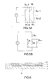
- the heating elements are driven in this way, the printed dots are arranged in zigzags and form an image as shown in FIG. 1.
- the main scanning direction is the direction in which the heating elements of the thermal print head are arranged
- the sub-scanning direction is the direction that is orthogonal to the main scanning direction.
- FIG. 2 shows the heating elements of the thermal print head and the temperature distribution in the ink layer of the thermal transfer ink ribbon.
- Reference Numeral 2 in the figure shows the heating elements of the thermal print head.
- the alternate driving is able to surely form isolated dots. Further, the dot size can be surely demodulated without being affected by adjoining dots and the multiple gradient printing utilizing the area gradation is enabled.
- FIG. 3A and 3B show the rough structure of the thermal print head heating elements and the corresponding temperature distribution in the ink layers.
- FIG. 4A and 4B show the rough structure of the thermal print head.
- the thermal print head is an edge-type thermal print head 3 as shown in FIG. 4A, wherein the heating elements 2 are formed near the edge of the thermal print head 3.
- the edge-type thermal print head 3 can be installed by inclining in the tangent direction of the pushing portion of the platen as shown in FIG. 11 that is shown later, printing media are easily supplied. Further, it has a merit in the down sizing of a system because a required space is less than a plane thermal print head.
- one pixel is formed with two heating elements 2a and 2b in one set as shown in FIG. 3A.
- Current applied to heat the heating elements passes through two heating elements 2a and 2b in series and returns back to a power source through a driving circuit (not shown) as shown by an arrow c in FIG. 3a. That is, a current circuit is not common with heating elements of other sets except the wiring to the power source.
- an normal plane type thermal print head 4 is in the structure to form one pixel by one heating element 2 as shown in FIG. 4B.
- Current applied to heat the heating element passes through the heating elements 2 and returns back to a power source via a common electrode 5 connected with all heating elements 2 as shown by an arrow d in FIG. 4B.
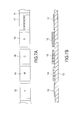
- FIG. 5A and 5B are electrical equivalent circuits expressed this flow of current.
- FIG. 5A is the circuit for the edge-type thermal print head 3 and
- FIG. 5B is the circuit for the plane-type thermal print head 4.
- Ri1 and Ri2 in FIG. 5A are electric resistances of the heating elements 2a and 2b.
- R1 in FIG. 5B shows electric resistance of the heating element 2 and Rc indicates electric resistance of the common electrode 5.
- the heating element 2 of the plane-type thermal print head 4 can be expressed as a parallel resistance group connected to the common electrode 5 in series as shown in FIG. 5B. As the resistance Rc is smaller than Ri, if the heating elements to be driven are less, the voltage drop can be ignored.
- the edge-type thermal print head 3 does not require the control according to the number of heating elements to be driven like in the plane-type thermal print head 4 and it has a merit that the driving control is simplified.
- the heating elements 2a and 2b are made one set and the temperature distribution in the ink layers is high at the central portion of the heating elements and somewhat low between two heating elements 2a and 2b but the temperature at the central portion of pixels does not become high.
- one heating element 2 is heated and the temperature distribution in the ink layer is high at the central portion of the heating element 1 as shown by f in FIG. 3B.
- the edge-type thermal print head 3 wherein the high temperature portions are close to adjacent heating elements and the central portions of pixels do not rise to a high temperature has a merit not to break the ink ribbons even when the heating elements are drive alternately.
- FIG. 6 schematically shows the structure of the intermediate transfer medium involved in this embodiment.
- the intermediate transfer medium 6 is formed on one surface of long film-shaped substrate member 7 by laminating a separatable layer 8 comprising a wax, a protective layer 9 comprising a resin 9 and a receptor layer 10 in this order.
- a separatable layer 8 comprising a wax
- a protective layer 9 comprising a resin 9 and a receptor layer 10
- film-shaped synthetic resins such as polyethylene terephthalate (hereinafter, simply referred to as PET) or polyethylene naphthalate (hereinafter, simply referred to as PEN).
- PET polyethylene terephthalate
- PEN polyethylene naphthalate
- the receptor 10 is demanded to be compatible with the ink layer of the ink ribbon that is described later and have a smooth receptor surface, and urethane resin, epoxy resin, acrylic resin, styrene resin or mixed resin of these resins are best suited.
- a mixed resin mainly comprising urethane resin and epoxy resin was coated on the protective layer 9 in the 5 thickness.
- the protective layer 9 is applied with a forgery or alteration preventing measure such as a hologram in many cases.
- the protective layer 9 applied with the hologram was also used.
- the thickness of the protective layer 9 in this embodiment was 10 m.
- FIG. 7 schematically shows the structure of a thermal transfer ink ribbon involved in this embodiment.
- a thermal transfer ink ribbon 11 comprises an yellow ink layer 13, a magenta ink layer 14, a cyan ink layer 15, a black ink layer 16, and a fluorescent ink layer 17.
- These ink layers are thermofusible multiple color ink layers arranged in a line on a long film-shaped support member 12 in the order shown above.
- the ink layers 13-17 are not necessarily arranged in the order described above but they can be arranged in the order that is decided according to the transparency of the ink layer.
- the fluorescent ink layer 17 is in the structure where a fluorescent pigment or dye that becomes visibly luminous when ultra-violet rays are applied is dispersed in a binder.
- the support member 12 is a 2-6 ⁇ m thick synthetic resin film, for example, a PET. In this embodiment, a 4.5 ⁇ m thick PET was used.
- the ink layers 13-17 have inorganic and organic pigments and fine grains dispersed in the resin made binders.
- thermofusible, colorless transparent or light color transparent resins having a melting point about 60 to 100°C, for example, a vinyl acetate-vinyl chloride copolymer, a vinyl acetate-ethylene copolymer, saturate polyester resin, epoxy resin, acrylic resin or styrene resin are suitably used.
- the binder comprising saturated polyester resin as a main component was used.
- fine particles are dispersion agents of pigments. Silica was used in this embodiment.
- desired colors are expressed in color ink dots by placing one upon another in order and therefore, if an ink layer transferred preceding was thick, the transferred dots were strongly affected by the uneven state of dots and defective transfer or broken dots could be produced. So, the ink layers 13-17 are desired thin as could as possible.
- the thin ink layers are desirable.
- a desirable thickness of the ink layers 13-17 is 0.4 to 1 ⁇ m.
- the thickness of the ink layers was made at 0.4 ⁇ m.
- the ink layer thickness of respective colors was changed from the relation with the superposing order and printing density of ink dots, all ink layers were adjusted to the thickness falling in the range of 0.4 to 1 ⁇ m.
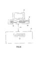
- FIG. 8 is a schematic diagram showing the structure of a printer system in this embodiment.
- This printer system is in the structure with a personal computer (hereinafter, simply referred to as PC) equipped with a display 42 connected to a printer 43 by a two-way communication means 44.
- the PC 41 is provided with an image processor 45 as an image processing means and an image developing processor 46 as an image developing processing means.
- the printer 43 is provided with a print control circuit 47 as a print control means.
- image data for printing by the printer 43 for example, face image data, character image data and other multi-valued image data are input from a scanner or a digital camera (not shown).
- image processes as color conversion, edge enhancement, etc. are applied to the input face image data and other multi-valued image data in the image processor 45.
- character image data are converted from a desired font into bit-mapped data.
- the multi-image data and the character image data converted into the bit-mapped data processed in the image processor 45 are subject to the image development in the image developing processor 46. That is, in the image developing processor 46, the input data are judged whether they are character image or multi-valued image. When the result of judgment is character image data, bit-mapped image data are sent to the print control circuit 47 of the printer 43 as image data to be printed.
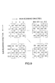
- FIG. 9 shows the pixel arrangement of the image data sent to the image developing processor 46 from the image processor 45.
- the numerals in the figure are the number of lines of pixels in the main scanning direction and the sub-scanning direction.
- the pixels of one line in the sub-scanning direction (for example, Sub-Scanning Line No. 1 to Main Scanning Line No. 1-512) are printed by driving the thermal print head after they are developed into data for driving the thermal print head and then, transferred to a driving circuit in the thermal print head (not shown).
- the odd numbered heating elements of the odd numbered lines in the sub-scanning direction and the even-numbered heating elements of the even-numbered lines in sub-scanning direction are alternately driven for each printing line by the thermal print head. Therefore, the image data that are not printed (the heating elements are not driven); that is, " ⁇ " data in this example are arranged in zigzags and pixel data that are printed according to the image data are arranged in the portion of not " ⁇ " data as shown in FIG. 10.
- the image array shown in FIG. 9 is converted into the image array as shown in FIG. 10 and sent to the print control circuit 47 of the printer 43 as image data to be printed.
- the print control circuit 47 and the PC 41 are connected with a two-way communication means 44 like a SCSI (Small Computer System Interface) or a USB (Universal Serial Bus), and image data to be printed and a printing start signal are sent from the PC 41 to the print control circuit 47 of the printer 43.
- a two-way communication means 44 like a SCSI (Small Computer System Interface) or a USB (Universal Serial Bus)
- image data to be printed and a printing start signal are sent from the PC 41 to the print control circuit 47 of the printer 43.
- the print control circuit 47 of the printer 43 receives image data from the PC 41 through the two-way communication means 44, converts the data into a thermal print head driving signal or controls the entire printing operation.
- the pixel array for the alternate driving is arranged by the image developing processor 46 of the PC 41 as described above and the print control circuit 47 of the printer 43 is required only to convert the pixel array into the thermal print head driving signal and the circuit is not complicated. Therefore, the print control circuit 47 can be made more simple and cheaper.
- FIG. 11 is a diagram schematically showing the structure of the printer 43.
- a thermal print head 22 that is a thermal printing means is provided on a platen roller 21.
- the thermal print head 22 is an edge type thermal print head as described above and is provided detachably on the platen roller 21 through the above-mentioned thermal transfer ink ribbon 11 and the intermediate transfer medium 6.
- the thermal transfer ink ribbon 11 is supplied between the platen roller 21 and the thermal print head 22 by a supply core 23 and taken up by a take-up core 24.
- a clamp roller 25 is provided to receive and convey the intermediate transfer medium 6.
- a clamp 26 is provided for clamping the intermediate transfer medium 6.
- a conveying roller 27 is provided for conveying the take-out intermediate transfer medium 6.
- a heating roller 28 that is a transfer means and a facing roller 29 facing to the heating roller 28 are provided.
- the heating roller 28 puts the intermediate transfer medium 6 supplied by the conveying roller 27 over a printing medium 30 (not shown) that is separately supplied and presses them jointly with the facing roller 29, and transfers an image printed on the intermediate transfer medium 6 on the printing medium 30 by heating the intermediate transfer medium 6 while rotating them.
- the intermediate transfer medium 6 is supplied between the platen roller 21 and the thermal print head 22 from the supply core 31 and then, supplied to the hear roller 29 via the clamp roller 25 and the conveying roller 27. After an image and the protector layer 9 on the intermediate transfer medium 6 are transferred on the printing medium 30, the intermediate transfer medium 6 is taken up by the take-up core (not shown) via a separation roller 32.
- the thermal transfer ink ribbon 11 is rolled up by the take-up core 24 to the print start position. Then, when the intermediate transfer medium 6 is clamped by both the clamp 26 and the clamp roller 25, the thermal print head 22, the thermal transfer ink ribbon 11 and the intermediate transfer medium 6 are pushed against the platen roller 21 under a desired pressure and the printing operation is started.
- the thermal print head 22 is driven by the thermal print head driving signal corresponding to the image data sent from the print control circuit 47, the clamp roller 25 is rotated at a rotational speed corresponding to the printing speed while clamping the intermediate transfer medium by both the claim and clamp roller 25 as shown in FIG. 12A, and the printing operation is thus carried out. At this time, the platen roller 21 is not forced to rotate for the problem of positional accuracy.
- the thermal print head 22 and the thermal transfer ink ribbon 11 are separated from the intermediate transfer medium 6.
- the supply core 31 and the clamp roller 25 are rotated in the direction opposite to that at the time of printing operation and the intermediate transfer medium 6 is rolled back to the supply core 31 side till the print starting position. Then, the printing operation is repeated again and the printing of an image in 3 colors is carried out.
- the intermediate transfer medium 6 is rolled back to the supply core 31 side to the printing start position by the supply core 31 and he clamp roller 25, and the intermediate transfer medium 6 is released from the clamp 27.
- the intermediate transfer medium 6 released from the clamp 26 is supplied to a heating roller 28 by the conveying roller 27 as shown in FIG. 12B.
- another printing medium is supplied from a printing medium supply tray (not shown).
- the leading edge of the image area of the intermediate transfer medium 6 is adapted to that of the printing medium 30 and the intermediate transfer medium 6 is press fit to the printing medium 30 by the heating roller 28 and the facing roller 29.
- the receptor layer 10 and the protective layer 9 on the intermediate transfer medium 6 are transferred on the printing medium 30 and the printing medium 30 is discharged to the separation roller 32 side.
- the separation roller 32 separates the substrate member 7 from the separable layer 8 of the intermediate transfer medium 6 and transfers the protective layer 9 and the receptor layer 10 on the printing medium 30.
- the transfer operation of the intermediate transfer medium 6 is completed.
- the intermediate transfer medium 6 is rolled back by the supply core 31 up to the print start position of the intermediate transfer medium 6, and the printing operation similar to the above is started again.
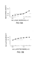
- FIG. 13A and FIG. 13B show representative reflection densities of a multi-valued image when the thickness of the black ink layer was changed.
- FIG. 13A shows the minimum density that can be reproduced while FIG. 13B shows the maximum density.
- the densities shown in FIG. 13A and FIG. 13B are mean densities by printing gradation patterns by the printer 43 and the minimum and maximum densities at 10 points were measured using a Macbeth densitometer. Although a required minimum density varies depending upon images, a desirable density is below 0.2 because the purpose of this embodiment is mainly for printing face images.
- the thickness of the ink layer for the reflection density below 0.2 is 1.0 ⁇ m or below.
- the thickness of the ink layer for the maximum density 1.5 or above is 0.4 ⁇ m or above. That is, it is seen that for the minimum density 0.2 or below and the maximum density 1.5 or above, the thickness of the ink layer is required to be 0.4-1.0 ⁇ m.
- all of the ink layers are set at 1 ⁇ m or below and therefore, even when any ink layer is used, it is possible not only to print multi-valued images but also to provide even binary images in sufficient density and achieve high quality images.
- FIG. 14 shows dispersion in reflection density of a black ink of multi-valued image when a rubber hardness of the platen 21 was changed.
- the distances of two horizontal lines (the lengths of the vertical lines) in FIG. 14 indicate standard deviations. Shown in FIG. 14 are standard deviations when halftone solid patterns of reflection density 1.0 were printed and densities at 10 points were measured using a Macbeth densitometer.
- the reproducibility of the halftone areas is especially satisfactory and the range of dispersion is desirable at ⁇ 1% or below.
- the rubber hardness of the platen becomes 80° or above as in FIG. 14, the range of dispersion (the standard deviation) can be made to below ⁇ 1%. In other words, it is seen that the rubber hardness of the platen 21 is required to be above 80°.
- FIG. 15 shows the dispersion of reflection density of multi-valued images when the press contacting force between the thermal print head 22 and the platen 21 was changed.
- the two horizontal line distances (the lengths of the vertical lines) in FIG. 15 indicate standard deviations. What are shown in FIG. 15 are standard deviations when halftone solid patterns of reflection density 1.0 were printed and densities at 10 points were measured using a Macbeth densitometer. Dispersion of reflection density can be lowered to ⁇ 1% or below when the pressure contact force is 3.0 N/cm or above.
- thermo transfer printing method a thermal transfer ink ribbon and a printer system capable of printing multi-valued images such as highly gradient color images, binary images like character images and fluorescent images preventing forgery/alteration.
Landscapes
- Physics & Mathematics (AREA)
- Optics & Photonics (AREA)
- Electronic Switches (AREA)
- Engineering & Computer Science (AREA)
- Mechanical Engineering (AREA)
- Thermal Transfer Or Thermal Recording In General (AREA)
Applications Claiming Priority (2)
| Application Number | Priority Date | Filing Date | Title |
|---|---|---|---|
| JP2001248096A JP4828739B2 (ja) | 2001-08-17 | 2001-08-17 | 熱転写記録方法、プリンタシステムおよび熱転写記録装置 |
| JP2001248096 | 2001-08-17 |
Publications (2)
| Publication Number | Publication Date |
|---|---|
| EP1285771A1 true EP1285771A1 (de) | 2003-02-26 |
| EP1285771B1 EP1285771B1 (de) | 2007-11-28 |
Family
ID=19077317
Family Applications (1)
| Application Number | Title | Priority Date | Filing Date |
|---|---|---|---|
| EP02255339A Expired - Lifetime EP1285771B1 (de) | 2001-08-17 | 2002-07-31 | Thermisches Übertragungsdruckverfahren und Druckersystem |
Country Status (6)
| Country | Link |
|---|---|
| US (1) | US6642948B2 (de) |
| EP (1) | EP1285771B1 (de) |
| JP (1) | JP4828739B2 (de) |
| KR (1) | KR100494006B1 (de) |
| DE (1) | DE60223763T2 (de) |
| TW (1) | TW542796B (de) |
Families Citing this family (21)
| Publication number | Priority date | Publication date | Assignee | Title |
|---|---|---|---|---|
| JP4495824B2 (ja) | 2000-03-21 | 2010-07-07 | 株式会社東芝 | 情報処理方法 |
| TW577814B (en) * | 2001-09-27 | 2004-03-01 | Toshiba Corp | Printing device and printing method |
| JP3665035B2 (ja) * | 2002-04-04 | 2005-06-29 | ニスカ株式会社 | 印刷装置及び印刷方法 |
| CA2435659A1 (en) * | 2002-07-23 | 2004-01-23 | Kabushiki Kaisha Toshiba | Image processing method |
| US20060056897A1 (en) * | 2003-01-29 | 2006-03-16 | C & I Systems Co., Ltd. | Thermal transfer ribbon for forgery-prevention |
| JP4227048B2 (ja) * | 2003-04-25 | 2009-02-18 | 株式会社東芝 | 画像処理システム |
| JP4788218B2 (ja) * | 2005-07-26 | 2011-10-05 | 凸版印刷株式会社 | 偽造防止効果のある画像記録体の製造方法 |
| JP5134822B2 (ja) * | 2006-01-31 | 2013-01-30 | 株式会社東芝 | 画像形成方法、画像形成装置および印刷物 |
| TWI291412B (en) * | 2006-08-17 | 2007-12-21 | Hi Touch Imaging Tech Co Ltd | Method for controlling printing of a printer |
| JP5119822B2 (ja) * | 2007-09-19 | 2013-01-16 | 株式会社Jvcケンウッド | 再転写方式の印刷装置及び再転写方式の印刷方法 |
| JP5127727B2 (ja) | 2008-04-23 | 2013-01-23 | 株式会社東芝 | ローラのクリ−ニング装置及びこのクリ−ニング装置を用いた印刷装置 |
| JP2010125714A (ja) * | 2008-11-27 | 2010-06-10 | Fujifilm Corp | 感熱転写方式による画像形成方法 |
| TW201204566A (en) * | 2010-07-19 | 2012-02-01 | Hiti Digital Inc | Method of increasing coloring stability of a ribbon and printing device thereof |
| JP5433626B2 (ja) * | 2011-05-02 | 2014-03-05 | 株式会社東芝 | 熱転写記録方法および熱転写記録装置 |
| CN102941740A (zh) * | 2012-11-29 | 2013-02-27 | 天津市赢事达办公用品厂 | 防伪荧光红条码色带 |
| CN104589814A (zh) * | 2013-10-30 | 2015-05-06 | 诚研科技股份有限公司 | 色带以及相片打印方法 |
| CN103660600B (zh) * | 2013-12-05 | 2015-12-02 | 北京亿赫伟信科技发展有限公司 | 热转印标识打印机 |
| JP2019081280A (ja) * | 2017-10-30 | 2019-05-30 | 凸版印刷株式会社 | 熱転写装置 |
| JP7307894B2 (ja) * | 2019-09-26 | 2023-07-13 | 大日本印刷株式会社 | 熱転写システムおよび熱転写方法 |
| US20240075751A1 (en) * | 2022-09-01 | 2024-03-07 | Entrust Corporation | Personalized identification document processing systems and methods |
| CN117416149B (zh) * | 2023-11-02 | 2025-03-07 | 珠海趣印科技有限公司 | 热转印打印方法、打印机和计算机可读存储介质 |
Citations (5)
| Publication number | Priority date | Publication date | Assignee | Title |
|---|---|---|---|---|
| EP0280241A2 (de) * | 1987-02-23 | 1988-08-31 | Canon Kabushiki Kaisha | Schreibwalze |
| US4780729A (en) * | 1986-10-31 | 1988-10-25 | Mitsubishi Denki Kabushiki Kaisha | Platen for use in thermal printer |
| DE19519956A1 (de) * | 1995-06-06 | 1996-12-12 | Phoenix Ag | Verwendung einer Kautschukmischung zur Herstellung von Walzen, insbesondere Schreibwalzen |
| JP2000135810A (ja) * | 1998-08-26 | 2000-05-16 | Toppan Printing Co Ltd | 画像形成装置および画像形成方法並びに画像形成体 |
| US6243121B1 (en) * | 1999-02-22 | 2001-06-05 | Fuji Photo Film Co., Ltd. | Thermal printer having thermal head which presses thermal recording material on platen roller at predetermined pressure |
Family Cites Families (5)
| Publication number | Priority date | Publication date | Assignee | Title |
|---|---|---|---|---|
| JPH0659739B2 (ja) | 1986-11-11 | 1994-08-10 | 日本ビクター株式会社 | 熱転写型印刷装置 |
| DE3806935A1 (de) * | 1988-03-03 | 1989-09-14 | Standard Elektrik Lorenz Ag | Drucker |
| JPH0659739A (ja) | 1992-08-07 | 1994-03-04 | Sumitomo Heavy Ind Ltd | 二重テーブル旋回装置 |
| JP2000225774A (ja) | 1999-02-05 | 2000-08-15 | Toshiba Corp | 熱転写インクリボン、画像形成方法、画像形成装置および認証用画像形成物 |
| JP4392972B2 (ja) | 2000-09-06 | 2010-01-06 | 株式会社東芝 | 熱転写記録媒体および画像形成装置 |
-
2001
- 2001-08-17 JP JP2001248096A patent/JP4828739B2/ja not_active Expired - Lifetime
-
2002
- 2002-07-12 US US10/193,166 patent/US6642948B2/en not_active Expired - Lifetime
- 2002-07-12 TW TW091115578A patent/TW542796B/zh not_active IP Right Cessation
- 2002-07-31 DE DE60223763T patent/DE60223763T2/de not_active Expired - Lifetime
- 2002-07-31 EP EP02255339A patent/EP1285771B1/de not_active Expired - Lifetime
- 2002-08-16 KR KR10-2002-0048331A patent/KR100494006B1/ko not_active Expired - Fee Related
Patent Citations (5)
| Publication number | Priority date | Publication date | Assignee | Title |
|---|---|---|---|---|
| US4780729A (en) * | 1986-10-31 | 1988-10-25 | Mitsubishi Denki Kabushiki Kaisha | Platen for use in thermal printer |
| EP0280241A2 (de) * | 1987-02-23 | 1988-08-31 | Canon Kabushiki Kaisha | Schreibwalze |
| DE19519956A1 (de) * | 1995-06-06 | 1996-12-12 | Phoenix Ag | Verwendung einer Kautschukmischung zur Herstellung von Walzen, insbesondere Schreibwalzen |
| JP2000135810A (ja) * | 1998-08-26 | 2000-05-16 | Toppan Printing Co Ltd | 画像形成装置および画像形成方法並びに画像形成体 |
| US6243121B1 (en) * | 1999-02-22 | 2001-06-05 | Fuji Photo Film Co., Ltd. | Thermal printer having thermal head which presses thermal recording material on platen roller at predetermined pressure |
Non-Patent Citations (1)
| Title |
|---|
| PATENT ABSTRACTS OF JAPAN vol. 2000, no. 08 6 October 2000 (2000-10-06) * |
Also Published As
| Publication number | Publication date |
|---|---|
| KR100494006B1 (ko) | 2005-06-13 |
| EP1285771B1 (de) | 2007-11-28 |
| KR20030015874A (ko) | 2003-02-25 |
| TW542796B (en) | 2003-07-21 |
| JP2003054144A (ja) | 2003-02-26 |
| DE60223763D1 (de) | 2008-01-10 |
| US20030035045A1 (en) | 2003-02-20 |
| JP4828739B2 (ja) | 2011-11-30 |
| DE60223763T2 (de) | 2008-11-20 |
| US6642948B2 (en) | 2003-11-04 |
Similar Documents
| Publication | Publication Date | Title |
|---|---|---|
| EP1285771B1 (de) | Thermisches Übertragungsdruckverfahren und Druckersystem | |
| EP1136276B1 (de) | Thermisches Übertragungsverfahren und Vorrichtung für dieses Verfahren | |
| EP1013463B1 (de) | Aufzeichnungsmaterial und Vorrichtung zum Aufzeichnen von Informationen | |
| US5982404A (en) | Thermal transfer type color printer | |
| EP2409841B1 (de) | Tintenstrahldrucker und tintenstrahldruckverfahren | |
| JPH0120992B2 (de) | ||
| EP0881073A1 (de) | Vorrichtung und Verfahren zur Herstellung eines Übertragungslaminats | |
| JP2002079765A (ja) | 熱転写記録媒体および画像形成装置 | |
| US6493015B2 (en) | Thermal recording system | |
| JP5433626B2 (ja) | 熱転写記録方法および熱転写記録装置 | |
| JP2003154694A (ja) | 中間転写印刷装置 | |
| US6121991A (en) | Forming authenticated images in a receiver | |
| JP4483748B2 (ja) | 画像形成体 | |
| JP2003025728A (ja) | 熱転写記録方法および熱転写インクリボン | |
| US20030048347A1 (en) | Thermal transfer printer | |
| JP2000085171A (ja) | 溶融型熱転写記録装置および溶融型熱転写記録方法 | |
| JPH01262177A (ja) | 印写装置 | |
| JPS59165694A (ja) | カラー熱転写方法 | |
| EP0584807A2 (de) | Thermisches Übertragungsaufzeichnungssystem | |
| JP2000225773A (ja) | 画像受理体及びこの形成方法 | |
| JPS6114990A (ja) | 感熱印刷方法 | |
| JPH01257083A (ja) | 印写装置 | |
| JPH01262161A (ja) | 印写装置 | |
| JPH04347691A (ja) | カラー記録媒体および記録方法 | |
| JPH07112542A (ja) | 熱転写プリンタ |
Legal Events
| Date | Code | Title | Description |
|---|---|---|---|
| PUAI | Public reference made under article 153(3) epc to a published international application that has entered the european phase |
Free format text: ORIGINAL CODE: 0009012 |
|
| 17P | Request for examination filed |
Effective date: 20020813 |
|
| AK | Designated contracting states |
Kind code of ref document: A1 Designated state(s): AT BE BG CH CY CZ DE DK EE ES FI FR GB GR IE IT LI LU MC NL PT SE SK TR Designated state(s): AT BE BG CH CY CZ DE DK EE ES FI FR GB GR IE IT LI LU MC NL PT SE SK TR |
|
| AX | Request for extension of the european patent |
Extension state: AL LT LV MK RO SI |
|
| AKX | Designation fees paid |
Designated state(s): AT BE BG CH CY CZ DE DK EE ES FI FR GB GR IE IT LI LU MC NL PT SE SK TR |
|
| 17Q | First examination report despatched |
Effective date: 20050701 |
|
| GRAP | Despatch of communication of intention to grant a patent |
Free format text: ORIGINAL CODE: EPIDOSNIGR1 |
|
| GRAS | Grant fee paid |
Free format text: ORIGINAL CODE: EPIDOSNIGR3 |
|
| GRAA | (expected) grant |
Free format text: ORIGINAL CODE: 0009210 |
|
| AK | Designated contracting states |
Kind code of ref document: B1 Designated state(s): AT BE BG CH CY CZ DE DK EE ES FI FR GB GR IE IT LI LU MC NL PT SE SK TR |
|
| REG | Reference to a national code |
Ref country code: IE Ref legal event code: FG4D |
|
| REG | Reference to a national code |
Ref country code: CH Ref legal event code: EP |
|
| REF | Corresponds to: |
Ref document number: 60223763 Country of ref document: DE Date of ref document: 20080110 Kind code of ref document: P |
|
| PG25 | Lapsed in a contracting state [announced via postgrant information from national office to epo] |
Ref country code: SE Free format text: LAPSE BECAUSE OF FAILURE TO SUBMIT A TRANSLATION OF THE DESCRIPTION OR TO PAY THE FEE WITHIN THE PRESCRIBED TIME-LIMIT Effective date: 20080228 Ref country code: NL Free format text: LAPSE BECAUSE OF FAILURE TO SUBMIT A TRANSLATION OF THE DESCRIPTION OR TO PAY THE FEE WITHIN THE PRESCRIBED TIME-LIMIT Effective date: 20071128 Ref country code: CH Free format text: LAPSE BECAUSE OF FAILURE TO SUBMIT A TRANSLATION OF THE DESCRIPTION OR TO PAY THE FEE WITHIN THE PRESCRIBED TIME-LIMIT Effective date: 20071128 Ref country code: LI Free format text: LAPSE BECAUSE OF FAILURE TO SUBMIT A TRANSLATION OF THE DESCRIPTION OR TO PAY THE FEE WITHIN THE PRESCRIBED TIME-LIMIT Effective date: 20071128 Ref country code: ES Free format text: LAPSE BECAUSE OF FAILURE TO SUBMIT A TRANSLATION OF THE DESCRIPTION OR TO PAY THE FEE WITHIN THE PRESCRIBED TIME-LIMIT Effective date: 20080311 |
|
| NLV1 | Nl: lapsed or annulled due to failure to fulfill the requirements of art. 29p and 29m of the patents act | ||
| PG25 | Lapsed in a contracting state [announced via postgrant information from national office to epo] |
Ref country code: BG Free format text: LAPSE BECAUSE OF FAILURE TO SUBMIT A TRANSLATION OF THE DESCRIPTION OR TO PAY THE FEE WITHIN THE PRESCRIBED TIME-LIMIT Effective date: 20080228 Ref country code: FI Free format text: LAPSE BECAUSE OF FAILURE TO SUBMIT A TRANSLATION OF THE DESCRIPTION OR TO PAY THE FEE WITHIN THE PRESCRIBED TIME-LIMIT Effective date: 20071128 |
|
| REG | Reference to a national code |
Ref country code: CH Ref legal event code: PL |
|
| PG25 | Lapsed in a contracting state [announced via postgrant information from national office to epo] |
Ref country code: AT Free format text: LAPSE BECAUSE OF FAILURE TO SUBMIT A TRANSLATION OF THE DESCRIPTION OR TO PAY THE FEE WITHIN THE PRESCRIBED TIME-LIMIT Effective date: 20071128 |
|
| ET | Fr: translation filed | ||
| PG25 | Lapsed in a contracting state [announced via postgrant information from national office to epo] |
Ref country code: DK Free format text: LAPSE BECAUSE OF FAILURE TO SUBMIT A TRANSLATION OF THE DESCRIPTION OR TO PAY THE FEE WITHIN THE PRESCRIBED TIME-LIMIT Effective date: 20071128 Ref country code: CZ Free format text: LAPSE BECAUSE OF FAILURE TO SUBMIT A TRANSLATION OF THE DESCRIPTION OR TO PAY THE FEE WITHIN THE PRESCRIBED TIME-LIMIT Effective date: 20071128 |
|
| PG25 | Lapsed in a contracting state [announced via postgrant information from national office to epo] |
Ref country code: BE Free format text: LAPSE BECAUSE OF FAILURE TO SUBMIT A TRANSLATION OF THE DESCRIPTION OR TO PAY THE FEE WITHIN THE PRESCRIBED TIME-LIMIT Effective date: 20071128 Ref country code: SK Free format text: LAPSE BECAUSE OF FAILURE TO SUBMIT A TRANSLATION OF THE DESCRIPTION OR TO PAY THE FEE WITHIN THE PRESCRIBED TIME-LIMIT Effective date: 20071128 |
|
| PG25 | Lapsed in a contracting state [announced via postgrant information from national office to epo] |
Ref country code: PT Free format text: LAPSE BECAUSE OF FAILURE TO SUBMIT A TRANSLATION OF THE DESCRIPTION OR TO PAY THE FEE WITHIN THE PRESCRIBED TIME-LIMIT Effective date: 20080428 |
|
| PLBE | No opposition filed within time limit |
Free format text: ORIGINAL CODE: 0009261 |
|
| STAA | Information on the status of an ep patent application or granted ep patent |
Free format text: STATUS: NO OPPOSITION FILED WITHIN TIME LIMIT |
|
| 26N | No opposition filed |
Effective date: 20080829 |
|
| PG25 | Lapsed in a contracting state [announced via postgrant information from national office to epo] |
Ref country code: GR Free format text: LAPSE BECAUSE OF FAILURE TO SUBMIT A TRANSLATION OF THE DESCRIPTION OR TO PAY THE FEE WITHIN THE PRESCRIBED TIME-LIMIT Effective date: 20080229 |
|
| GBPC | Gb: european patent ceased through non-payment of renewal fee |
Effective date: 20080731 |
|
| PG25 | Lapsed in a contracting state [announced via postgrant information from national office to epo] |
Ref country code: MC Free format text: LAPSE BECAUSE OF NON-PAYMENT OF DUE FEES Effective date: 20080731 |
|
| PG25 | Lapsed in a contracting state [announced via postgrant information from national office to epo] |
Ref country code: EE Free format text: LAPSE BECAUSE OF FAILURE TO SUBMIT A TRANSLATION OF THE DESCRIPTION OR TO PAY THE FEE WITHIN THE PRESCRIBED TIME-LIMIT Effective date: 20071128 |
|
| PG25 | Lapsed in a contracting state [announced via postgrant information from national office to epo] |
Ref country code: GB Free format text: LAPSE BECAUSE OF NON-PAYMENT OF DUE FEES Effective date: 20080731 |
|
| PG25 | Lapsed in a contracting state [announced via postgrant information from national office to epo] |
Ref country code: CY Free format text: LAPSE BECAUSE OF FAILURE TO SUBMIT A TRANSLATION OF THE DESCRIPTION OR TO PAY THE FEE WITHIN THE PRESCRIBED TIME-LIMIT Effective date: 20071128 Ref country code: IE Free format text: LAPSE BECAUSE OF NON-PAYMENT OF DUE FEES Effective date: 20080731 |
|
| PG25 | Lapsed in a contracting state [announced via postgrant information from national office to epo] |
Ref country code: LU Free format text: LAPSE BECAUSE OF NON-PAYMENT OF DUE FEES Effective date: 20080731 |
|
| PG25 | Lapsed in a contracting state [announced via postgrant information from national office to epo] |
Ref country code: TR Free format text: LAPSE BECAUSE OF FAILURE TO SUBMIT A TRANSLATION OF THE DESCRIPTION OR TO PAY THE FEE WITHIN THE PRESCRIBED TIME-LIMIT Effective date: 20071128 |
|
| PG25 | Lapsed in a contracting state [announced via postgrant information from national office to epo] |
Ref country code: IT Free format text: LAPSE BECAUSE OF NON-PAYMENT OF DUE FEES Effective date: 20080731 |
|
| REG | Reference to a national code |
Ref country code: FR Ref legal event code: PLFP Year of fee payment: 15 |
|
| REG | Reference to a national code |
Ref country code: FR Ref legal event code: PLFP Year of fee payment: 16 |
|
| REG | Reference to a national code |
Ref country code: FR Ref legal event code: PLFP Year of fee payment: 17 |
|
| PGFP | Annual fee paid to national office [announced via postgrant information from national office to epo] |
Ref country code: FR Payment date: 20210611 Year of fee payment: 20 |
|
| PGFP | Annual fee paid to national office [announced via postgrant information from national office to epo] |
Ref country code: DE Payment date: 20210630 Year of fee payment: 20 |
|
| REG | Reference to a national code |
Ref country code: DE Ref legal event code: R071 Ref document number: 60223763 Country of ref document: DE |