EP0584807A2 - Thermisches Übertragungsaufzeichnungssystem - Google Patents
Thermisches Übertragungsaufzeichnungssystem Download PDFInfo
- Publication number
- EP0584807A2 EP0584807A2 EP93113579A EP93113579A EP0584807A2 EP 0584807 A2 EP0584807 A2 EP 0584807A2 EP 93113579 A EP93113579 A EP 93113579A EP 93113579 A EP93113579 A EP 93113579A EP 0584807 A2 EP0584807 A2 EP 0584807A2
- Authority
- EP
- European Patent Office
- Prior art keywords
- ink
- sheet
- layer
- thermal
- ink sheet
- Prior art date
- Legal status (The legal status is an assumption and is not a legal conclusion. Google has not performed a legal analysis and makes no representation as to the accuracy of the status listed.)
- Withdrawn
Links
Images


Classifications
-
- B—PERFORMING OPERATIONS; TRANSPORTING
- B41—PRINTING; LINING MACHINES; TYPEWRITERS; STAMPS
- B41M—PRINTING, DUPLICATING, MARKING, OR COPYING PROCESSES; COLOUR PRINTING
- B41M5/00—Duplicating or marking methods; Sheet materials for use therein
- B41M5/26—Thermography ; Marking by high energetic means, e.g. laser otherwise than by burning, and characterised by the material used
- B41M5/382—Contact thermal transfer or sublimation processes
- B41M5/38207—Contact thermal transfer or sublimation processes characterised by aspects not provided for in groups B41M5/385 - B41M5/395
- B41M5/38221—Apparatus features
Definitions
- the present invention relates to a thermal transfer type recording device suitable for use in printers, facsimile machines and so on and particularly to such a recording device for printing a colored or half-tone image on a sheet of paper having low smoothness.
- Fig. 5 shows the printing section of a typical thermal-transfer type recording device constructed in accordance with the prior art.
- the printing section comprises a thermal head for heating an ink sheet 4.
- the thermal head includes a convex part glaze 2 formed therein at the tip end and a recessed heating resistor 3 formed in the apex of the part glaze 2.
- the ink sheet 4 consists of a base film 5 and an ink layer 6.
- Reference numeral 7 denotes a recording sheet of paper.
- Reference numeral 8 designates a platen roller for pinching the ink and recording sheets 4, 7 between the platen roller 8 and the thermal head 1 under pressure.
- the ink layer 6 is formed of a mixture consisting of a coloring agent (e.g. pigment or dye) and a binder (e.g. wax).
- the ink layer 6 is partially heated so as to adhere to the recording sheet 7 by the thermal head 1. Since the adhered ink immediately solidifies, only the solidified ink parts in a desired pattern to be transferred remain on the recording sheet 7 when the ink sheet 4 is separated from the recording sheet 7.
- the prior art has two proposed approaches: One of these approaches is to use a high-viscosity ink containing a resin-based binder. Before the ink solidifies, the ink sheet 4 is separated from the recording sheet 7 to transfer the ink to the recording sheet 7 in the form of a bridge over a recess in the recording sheet surface.
- the first approach can be realized only in a serial printer with the thermal head 1 being very rapidly moved, rather than a line printer.
- the second approach is described in "NIKKEI ELECTRONICS", No. 535, September 2, 1991, pp.163.
- the second approach utilizes a thick-film thermal head including a protruding heating resistor with a convex part glaze which would be used only in the thin-film thermal head.
- the convex part glaze of the heating resistor is formed with two steps and the ink in the ink sheet has a reduced melting viscosity.
- the ink can easily enter the recesses in the low-smoothness surface of any recording sheet.
- the second approach can sufficiently perform its function only in the monochrome printer.
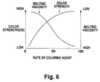
- Fig. 6 is a graph showing variations in color strength and melting viscosity (easy transfer) relative to rate of coloring agent in the ink. It will be apparent from Fig. 6 that as the color strength increases, the melting viscosity increases or the transfer becomes more difficult. The color printing requires a reduction in the melting viscosity to facilitate the transfer since it is difficult to transfer the ink to the ordinary paper, as described. However, the color strength will then be reduced.
- the present invention provides a thermal-transfer type recording device using ink sheet, which is carrying an ink of higher viscosity at a position adjacent to the base film and is also carrying an ink of lower viscosity at another position remote from the base film, this recording device further comprising a thermal head including a part glaze with a convex heating resistor.
- the thermal-transfer type recording device of the present invention can facilitate causing the ink to enter the low-smoothness surface of the recording sheet. Therefore, the recesses in the low-smoothness surface of the recording sheet can be filled with the ink to facilitate the transfer of ink.
- Fig. 1 is a view showing the printing part of a thermal-transfer type recording device which is one embodiment of the present invention.
- Fig. 2 is a graph illustrating the improved quality of print in the first embodiment of the present invention.
- Fig. 3 is a fragmentary cross-section of an ink sheet constructed in accordance with the second embodiment of the present invention.
- Fig. 4 is a schematic view showing a printing part constructed in accordance with the third embodiment of the present invention.
- Fig. 5 is a schematic cross-section of a printing part constructed in accordance with the prior art.
- Fig. 6 is a graph showing the characteristics of the conventional inks.
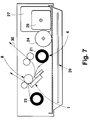
- Fig. 7 is a schematic view showing the entire arrangement of a thermal-transfer type recording device.
- a thermal head 1 comprising a part glaze 2 and a heating resistor 3 of ruthenium tetroxide having a width of 0.12 mm and a height of 5 ⁇ m.
- Fig. 1 also shows an ink sheet 4 comprising a base film of polyethylene having a thickness of 4.5 ⁇ , a coloring agent layer consisting of a binder and a coloring agent of 40% by weight mixed with the binder, the coloring agent layer having a thickness of 2 ⁇ m, and a wax layer 10 mostly formed by a wax of low melting viscosity and having a thickness of 1 ⁇ m.
- An ink layer 6 is formed by the layers 9 and 10.
- the ink sheet 4 comprises the ink layer 6 formed on the base film 5 by the coloring agent layer 9 and wax layer 10.
- the coloring agent used in this embodiment contains phthalocyanine blue as cyan, rhodamine lake T as magenta and benzine yellow G as yellow.
- the wax comprises carnauba wax and microcrystalline wax.
- the ink sheet 4 is moved to the thermal head 1 by a feed means 11 which is mounted in the recording device.
- the feed means 11 may be of any suitable form well known in the art, for example, roller means.
- the heating resistor 3 is first energized in respone to print data supplied from any suitable means (not shown).
- the heating value of the heating resistor 3 is 0.3 mJ/dot. Heat is transmitted from the heating resistor 3 through the base film 5 to the ink layer 6 in which the coloring agent and wax layers 9 and 10 will be fused.
- the molten wax easily enters and fills recesses in the recording sheet 7 since the melting viscosity of the wax is low.
- a force urging the wax layer 10 against the recording sheet 7 is locally increased to facilitate the filling of the recesses in the recording sheet 7 with the molten wax.
- the ink sheet 4 is separated from the recording sheet 7 while leaving the wax layer 10 with the coloring agent layer 9 on the surface of the recording sheet 7 in the desired pattern. The portion thus transferred is maintained increased in color tone to provide a color printed material.
- Fig. 2 shows the improved quality of print. It will be apparent from Fig. 2 that the rate of transfer as well as the rate of dot reproducibility become maximum when the thermal head of the present invention having the thick-film part glaze (with the convex heating resistor) is used with the aforementioned composition of ink as in the first embodiment.
- Fig. 3 shows an ink sheet 4 which is another embodiment of the present invention.
- the ink sheet 4 includes an ink layer 6 which functions in a combination of a coloring agent layer 9 with a wax layer 10 as in the first embodiment.
- the graph on the right side of Fig. 3 shows the proportion of the coloring agent to the wax component in the ink layer 6 by weight.
- the coloring agent increases more than the wax toward the base film 5 while the wax gradually increases more than the coloring agent in the opposite direction.
- the printing can be carried out substantially in the same manner as in the first embodiment. More particularly, the side of the ink layer 6 adjacent to the recording sheet functions to fill the recesses in the surface of the recording sheet while the other side of the ink layer 6 adjacent to the base film 5 functions to maintain the color tone.
- Fig. 4 shows a further ink sheet 4 which comprises a coloring agent layer 9 consisting of a binder of polyester resin and a coloring agent dispersed in the binder.
- a coloring agent layer 9 consisting of a binder of polyester resin and a coloring agent dispersed in the binder.
- the ink sheet 4 also comprises a wax layer 10 that can easily be fused by heat from the thermal head.
- the ink sheet 6 of Fig. 4 can be used substantially with such an advantage as in the first embodiment. More particularly, the molten wax layer 10 penetrates into the recesses in the recording sheet and functions as an adhesive layer between the coloring agent layer 9 and the surface of a recording sheet (not shown) after the molten wax has solidified. At this time, the coloring agent layer 9 will almost be not fused and will be transferred onto the recording sheet by the block-like parts of the coloring agent layer 9 being drawn by the wax layer 10.
- the size of each dot to be transferred is determined by the range of fusion in the wax layer 10, rather than that of the coloring agent layer 9. As shown in Fig. 4, accordingly, a dot 11 smaller than the heating resistor 3 can be formed on the recording sheet. Fig. 4 also shows a heating range by a broken line.
- the third embodiment has such an advantage that the size of dots to be transferred can be varied by changing the degree of heating. This means that a half-tone print can be performed according to the third embodiment of the present invention.
- the wax layer 10 of the present invention may contain any other suitable component such as adhesive, in addition to the wax component, without reducing the advantages thereof.
- the wax layer 10 may be mixed with an undercooling substance such as ricinoleic amide.
- an undercooling substance such as ricinoleic amide.
- the wax layer 6 is maintained in a molten state for a prolonged time period without solidifying. This provides the same effect as the melting viscosity being decreased.
- Fig. 7 shows a thermal-transfer type recording device to which the present invention can be applied.
- an ink sheet 4 is unwound from a roller 21 and then moved to a roller 23 while passing between a thermal head 1 and a platen roller 8.
- the ink sheet 4 is then wound about the roller 23.
- the two rollers 21 and 23 are driven by a motor 24 while the thermal head 11 is driven by a motor 25.
- the motors 24 and 25 are powered by a power source 27 under control of a controller 29.
- a supply means 11 will be defined by the rollers 21 and 23, motor 24, power source 27 and controller 29.
- the thermal head 1 includes a part glaze layer as described.
- the ink sheet 4 may be any one of the ink sheets described in the previously described embodiments of the present invention. Consequently, the thermal-transfer type recording device can clearly print a recording sheet having a surface of low smoothness.
- the present invention uses an ink sheet having different functions separated in the direction of thickness of the ink sheet, that is, including a coloring component contained in the ink sheet on the side adjacent to the base film and a wax component of low melting viscosity mainly contained in the ink sheet on the opposite side adjacent to the recording sheet.
- the present invention also uses a thermal head having a part glaze for increasing a force urging the ink layer against the recording sheet. Therefore, the present invention can provide a thermal-transfer type color recording device which can print a recording sheet of low smoothness and maintain the color tone constant.
Landscapes
- Physics & Mathematics (AREA)
- Optics & Photonics (AREA)
- Thermal Transfer Or Thermal Recording In General (AREA)
- Electronic Switches (AREA)
Applications Claiming Priority (2)
| Application Number | Priority Date | Filing Date | Title |
|---|---|---|---|
| JP229870/92 | 1992-08-28 | ||
| JP4229870A JPH0671920A (ja) | 1992-08-28 | 1992-08-28 | 熱転写記録装置 |
Publications (2)
| Publication Number | Publication Date |
|---|---|
| EP0584807A2 true EP0584807A2 (de) | 1994-03-02 |
| EP0584807A3 EP0584807A3 (de) | 1995-03-29 |
Family
ID=16898999
Family Applications (1)
| Application Number | Title | Priority Date | Filing Date |
|---|---|---|---|
| EP93113579A Withdrawn EP0584807A3 (de) | 1992-08-28 | 1993-08-25 | Thermisches Übertragungsaufzeichnungssystem. |
Country Status (2)
| Country | Link |
|---|---|
| EP (1) | EP0584807A3 (de) |
| JP (1) | JPH0671920A (de) |
Families Citing this family (1)
| Publication number | Priority date | Publication date | Assignee | Title |
|---|---|---|---|---|
| JP6209019B2 (ja) * | 2013-08-20 | 2017-10-04 | ローム株式会社 | サーマルプリントヘッド、サーマルプリンタ |
Family Cites Families (3)
| Publication number | Priority date | Publication date | Assignee | Title |
|---|---|---|---|---|
| JPS63246281A (ja) * | 1986-11-01 | 1988-10-13 | Ricoh Co Ltd | 転写記録媒体 |
| JPS6453867A (en) * | 1987-08-26 | 1989-03-01 | Hitachi Ltd | Thermal transfer printer |
| JPH023337A (ja) * | 1988-06-17 | 1990-01-08 | Canon Inc | 感熱転写記録方法 |
-
1992
- 1992-08-28 JP JP4229870A patent/JPH0671920A/ja active Pending
-
1993
- 1993-08-25 EP EP93113579A patent/EP0584807A3/de not_active Withdrawn
Also Published As
| Publication number | Publication date |
|---|---|
| EP0584807A3 (de) | 1995-03-29 |
| JPH0671920A (ja) | 1994-03-15 |
Similar Documents
| Publication | Publication Date | Title |
|---|---|---|
| USRE37726E1 (en) | Method for transferring hot melt ink to a recording medium | |
| JP3523724B2 (ja) | 熱転写式カラープリンタ | |
| JP2850930B2 (ja) | 溶融型熱転写プリントシステム | |
| EP0850776B1 (de) | Tintenstrahlaufzeichnungsdruckverfahren, das eine Phasenaustauschtinte verwendet | |
| JPH10337912A (ja) | 2色プリンタおよび2色ラベル | |
| EP0584807A2 (de) | Thermisches Übertragungsaufzeichnungssystem | |
| JPS58138685A (ja) | カラ−熱転写用記録媒体 | |
| US6133929A (en) | Melting type thermal transfer recording device and melting type thermal transfer recording method | |
| JPH1086463A (ja) | 抵抗式熱プリンタ | |
| JP3447140B2 (ja) | サーマルプリンタの印刷制御方法 | |
| JP3412447B2 (ja) | 記録装置 | |
| JPH06270441A (ja) | フルカラー画像形成方法およびその装置 | |
| JPH06206364A (ja) | プリンタ | |
| JP2000225773A (ja) | 画像受理体及びこの形成方法 | |
| JPH06143634A (ja) | 改良された熱転写プリンタ及びそれを用いた印字方法 | |
| JPH08216540A (ja) | 多色インクシート、熱転写多色記録装置及び熱転写多色記録方法 | |
| JPH0361583A (ja) | 感熱転写材 | |
| JPH06218966A (ja) | 熱転写記録装置 | |
| JPS61188187A (ja) | 画像形成方法 | |
| JPH0761011A (ja) | 溶融型熱転写記録装置及び溶融型熱転写色剤シート | |
| JPS6394885A (ja) | 感熱転写記録媒体 | |
| JPH04224987A (ja) | 熱転写プリント方法 | |
| JPH07148963A (ja) | 熱転写プリンタの印刷方法 | |
| JPH03288666A (ja) | 熱転写画像形成装置及び画像形成方法 | |
| JP2002331756A (ja) | 印刷用紙、印刷物及び印刷システム |
Legal Events
| Date | Code | Title | Description |
|---|---|---|---|
| PUAI | Public reference made under article 153(3) epc to a published international application that has entered the european phase |
Free format text: ORIGINAL CODE: 0009012 |
|
| AK | Designated contracting states |
Kind code of ref document: A2 Designated state(s): DE FR GB |
|
| PUAL | Search report despatched |
Free format text: ORIGINAL CODE: 0009013 |
|
| AK | Designated contracting states |
Kind code of ref document: A3 Designated state(s): DE FR GB |
|
| 17P | Request for examination filed |
Effective date: 19950711 |
|
| 17Q | First examination report despatched |
Effective date: 19950816 |
|
| 18D | Application deemed to be withdrawn |
Effective date: 19951227 |