EP1286850B1 - Procede et dispositif de gestion de fonctions specifiques a l'interieur d'un vehicule de transport de charge lors du dechargement et/ou du chargement de la plateforme de transport de charge du vehicule - Google Patents
Procede et dispositif de gestion de fonctions specifiques a l'interieur d'un vehicule de transport de charge lors du dechargement et/ou du chargement de la plateforme de transport de charge du vehicule Download PDFInfo
- Publication number
- EP1286850B1 EP1286850B1 EP01937103A EP01937103A EP1286850B1 EP 1286850 B1 EP1286850 B1 EP 1286850B1 EP 01937103 A EP01937103 A EP 01937103A EP 01937103 A EP01937103 A EP 01937103A EP 1286850 B1 EP1286850 B1 EP 1286850B1
- Authority
- EP
- European Patent Office
- Prior art keywords
- vehicle
- load
- organ
- carrying
- brakes
- Prior art date
- Legal status (The legal status is an assumption and is not a legal conclusion. Google has not performed a legal analysis and makes no representation as to the accuracy of the status listed.)
- Expired - Lifetime
Links
- 238000000034 method Methods 0.000 title claims abstract description 11
- 210000000056 organ Anatomy 0.000 claims abstract description 55
- 230000007935 neutral effect Effects 0.000 claims abstract description 20
- 230000004913 activation Effects 0.000 claims description 11
- 230000033001 locomotion Effects 0.000 claims description 6
- 230000003213 activating effect Effects 0.000 description 4
- 238000005516 engineering process Methods 0.000 description 4
- 230000005540 biological transmission Effects 0.000 description 2
- 230000000881 depressing effect Effects 0.000 description 2
- 230000015556 catabolic process Effects 0.000 description 1
- 238000010276 construction Methods 0.000 description 1
- 230000008878 coupling Effects 0.000 description 1
- 238000010168 coupling process Methods 0.000 description 1
- 238000005859 coupling reaction Methods 0.000 description 1
- 230000001419 dependent effect Effects 0.000 description 1
- 238000001514 detection method Methods 0.000 description 1
- 210000004247 hand Anatomy 0.000 description 1
- 210000003813 thumb Anatomy 0.000 description 1
Images

Classifications
-
- B—PERFORMING OPERATIONS; TRANSPORTING
- B60—VEHICLES IN GENERAL
- B60T—VEHICLE BRAKE CONTROL SYSTEMS OR PARTS THEREOF; BRAKE CONTROL SYSTEMS OR PARTS THEREOF, IN GENERAL; ARRANGEMENT OF BRAKING ELEMENTS ON VEHICLES IN GENERAL; PORTABLE DEVICES FOR PREVENTING UNWANTED MOVEMENT OF VEHICLES; VEHICLE MODIFICATIONS TO FACILITATE COOLING OF BRAKES
- B60T7/00—Brake-action initiating means
- B60T7/02—Brake-action initiating means for personal initiation
- B60T7/08—Brake-action initiating means for personal initiation hand actuated
- B60T7/10—Disposition of hand control
- B60T7/107—Disposition of hand control with electrical power assistance
-
- B—PERFORMING OPERATIONS; TRANSPORTING
- B60—VEHICLES IN GENERAL
- B60P—VEHICLES ADAPTED FOR LOAD TRANSPORTATION OR TO TRANSPORT, TO CARRY, OR TO COMPRISE SPECIAL LOADS OR OBJECTS
- B60P1/00—Vehicles predominantly for transporting loads and modified to facilitate loading, consolidating the load, or unloading
- B60P1/04—Vehicles predominantly for transporting loads and modified to facilitate loading, consolidating the load, or unloading with a tipping movement of load-transporting element
-
- B—PERFORMING OPERATIONS; TRANSPORTING
- B60—VEHICLES IN GENERAL
- B60P—VEHICLES ADAPTED FOR LOAD TRANSPORTATION OR TO TRANSPORT, TO CARRY, OR TO COMPRISE SPECIAL LOADS OR OBJECTS
- B60P1/00—Vehicles predominantly for transporting loads and modified to facilitate loading, consolidating the load, or unloading
- B60P1/04—Vehicles predominantly for transporting loads and modified to facilitate loading, consolidating the load, or unloading with a tipping movement of load-transporting element
- B60P1/16—Vehicles predominantly for transporting loads and modified to facilitate loading, consolidating the load, or unloading with a tipping movement of load-transporting element actuated by fluid-operated mechanisms
- B60P1/162—Vehicles predominantly for transporting loads and modified to facilitate loading, consolidating the load, or unloading with a tipping movement of load-transporting element actuated by fluid-operated mechanisms the hydraulic system itself
-
- B—PERFORMING OPERATIONS; TRANSPORTING
- B60—VEHICLES IN GENERAL
- B60W—CONJOINT CONTROL OF VEHICLE SUB-UNITS OF DIFFERENT TYPE OR DIFFERENT FUNCTION; CONTROL SYSTEMS SPECIALLY ADAPTED FOR HYBRID VEHICLES; ROAD VEHICLE DRIVE CONTROL SYSTEMS FOR PURPOSES NOT RELATED TO THE CONTROL OF A PARTICULAR SUB-UNIT
- B60W10/00—Conjoint control of vehicle sub-units of different type or different function
- B60W10/10—Conjoint control of vehicle sub-units of different type or different function including control of change-speed gearings
-
- B—PERFORMING OPERATIONS; TRANSPORTING
- B60—VEHICLES IN GENERAL
- B60W—CONJOINT CONTROL OF VEHICLE SUB-UNITS OF DIFFERENT TYPE OR DIFFERENT FUNCTION; CONTROL SYSTEMS SPECIALLY ADAPTED FOR HYBRID VEHICLES; ROAD VEHICLE DRIVE CONTROL SYSTEMS FOR PURPOSES NOT RELATED TO THE CONTROL OF A PARTICULAR SUB-UNIT
- B60W10/00—Conjoint control of vehicle sub-units of different type or different function
- B60W10/18—Conjoint control of vehicle sub-units of different type or different function including control of braking systems
-
- B—PERFORMING OPERATIONS; TRANSPORTING
- B60—VEHICLES IN GENERAL
- B60W—CONJOINT CONTROL OF VEHICLE SUB-UNITS OF DIFFERENT TYPE OR DIFFERENT FUNCTION; CONTROL SYSTEMS SPECIALLY ADAPTED FOR HYBRID VEHICLES; ROAD VEHICLE DRIVE CONTROL SYSTEMS FOR PURPOSES NOT RELATED TO THE CONTROL OF A PARTICULAR SUB-UNIT
- B60W30/00—Purposes of road vehicle drive control systems not related to the control of a particular sub-unit, e.g. of systems using conjoint control of vehicle sub-units
- B60W30/18—Propelling the vehicle
- B60W30/1819—Propulsion control with control means using analogue circuits, relays or mechanical links
-
- B—PERFORMING OPERATIONS; TRANSPORTING
- B60—VEHICLES IN GENERAL
- B60Y—INDEXING SCHEME RELATING TO ASPECTS CROSS-CUTTING VEHICLE TECHNOLOGY
- B60Y2200/00—Type of vehicle
- B60Y2200/10—Road Vehicles
- B60Y2200/14—Trucks; Load vehicles, Busses
-
- B—PERFORMING OPERATIONS; TRANSPORTING
- B60—VEHICLES IN GENERAL
- B60Y—INDEXING SCHEME RELATING TO ASPECTS CROSS-CUTTING VEHICLE TECHNOLOGY
- B60Y2200/00—Type of vehicle
- B60Y2200/10—Road Vehicles
- B60Y2200/14—Trucks; Load vehicles, Busses
- B60Y2200/145—Haulage vehicles, trailing trucks
-
- F—MECHANICAL ENGINEERING; LIGHTING; HEATING; WEAPONS; BLASTING
- F16—ENGINEERING ELEMENTS AND UNITS; GENERAL MEASURES FOR PRODUCING AND MAINTAINING EFFECTIVE FUNCTIONING OF MACHINES OR INSTALLATIONS; THERMAL INSULATION IN GENERAL
- F16H—GEARING
- F16H61/00—Control functions within control units of change-speed- or reversing-gearings for conveying rotary motion ; Control of exclusively fluid gearing, friction gearing, gearings with endless flexible members or other particular types of gearing
- F16H61/16—Inhibiting or initiating shift during unfavourable conditions , e.g. preventing forward-reverse shift at high vehicle speed, preventing engine overspeed
- F16H2061/168—Forced shifts into neutral for safety reasons, e.g. in case of transmission failure or emergency braking
-
- F—MECHANICAL ENGINEERING; LIGHTING; HEATING; WEAPONS; BLASTING
- F16—ENGINEERING ELEMENTS AND UNITS; GENERAL MEASURES FOR PRODUCING AND MAINTAINING EFFECTIVE FUNCTIONING OF MACHINES OR INSTALLATIONS; THERMAL INSULATION IN GENERAL
- F16H—GEARING
- F16H61/00—Control functions within control units of change-speed- or reversing-gearings for conveying rotary motion ; Control of exclusively fluid gearing, friction gearing, gearings with endless flexible members or other particular types of gearing
- F16H61/20—Preventing gear creeping ; Transmission control during standstill, e.g. hill hold control
Definitions
- the present invention relates to a device for controlling specific functions of a load-carrying vehicle when dumping and/or loading the load-carrying platform of the vehicle.
- the load-carrying vehicle is preferably a construction machine.
- the invention will in the following be described in the context of a waist controlled dumper. This is to be seen as a preferred, but in no way limiting application of the invention.
- the invention can, for example, also be used in a truck.
- the invention also relates to a method for said control.
- a waist controlled dumper also known as a basket
- a number of operations are necessary on the part of the driver of the vehicle. These operations will be described below.
- the vehicle is backed up against an intended dumping position, and the platform is tilted, allowing the driver to see the ground below and behind the platform.
- the position of the platform is controlled by means of a tilting lever arranged in the cabin.
- the tilting lever is usually arranged to the right of the driver, for manoeuvring with his right hand.
- the gas pedal is released, and instead the brake pedal is activated.
- a gear lever coupled to the gear box is brought to the neutral position.
- the brakes are either activated by means of the brake pedal, or the parking brake of the vehicle is utilized. Following the dumping and the return of the platform to the initial position, a gear is engaged, the activated brake is released and the vehicle is driven away.
- Loading of a waist controlled dumper according to previous technology can for example be done in the following manner.
- the dumper is backed up against an intended loading position, and is braked.
- the brake is then kept activated, and/or the parking brake is activated, and the gear box is brought to the neutral position.
- a gear is engaged and the vehicle is driven away.
- the brakes are subjected to large forces.
- the parking brake is usually too weak to withstand these forces, leading to the driver instead utilizing the brakes of the vehicle.
- this is tiresome for the driver since he must keep the brake pedal pressed down.
- a load-carrying vehicle having the features of the preamble of claim 1 is known from JP-A-62258829.
- a purpose of the invention is to obtain a device which simplifies and facilitates the manoeuvring of a load-carrying vehicle when dumping and/or loading.
- a device is achieved which contributes to improved safety during said manoeuvring relative to previously known technology.
- a device is desired which secures the parking brake function of the vehicle with reduced risk of unnecessary wear.
- the manoeuvring organ is arranged in such a way that it is within reach of the driver while the driver at the same time is manoeuvring the steering wheel and the tilting lever. This means that the driver can bring about the neutral position of the gear box without moving his hands from the steering wheel or the tilting lever respectively, which leads to improved safety.
- the manoeuvring organ is arranged on a panel in the cabin, in the immediate vicinity of a tilting lever in such a way that it can be reached by the driver while simultaneously manoeuvring the tilting lever with the same hand.
- the driver can bring the gear box to the neutral position by manoeuvring the manoeuvring organ with the same hand, preferably the right hand, that he is using to manoeuvre the tilting lever with.
- the driver does not need to use his left hand to manoeuvre the gear lever, but has his left hand free to control the steering wheel of the vehicle.
- an organ is connected to the control unit for detecting a manual movement of a gear lever connected to the gear box.
- said brakes can be released only after the gear box has been brought to a gear position separate from the neutral position, which means that the transmission is in a tractive position. This reduces the risk that the vehicle will start to move before the tractive position is reached, which is risky especially when the vehicle is on a slope.
- an organ is connected to the control unit for detecting the speed of the vehicle with the purpose of maintaining said brakes in a non-active position and the current gear of the gear box in spite of an activation of the manoeuvring organ when the speed of the vehicle exceeds a predetermined speed. This eliminates the risk that the brakes will be activated when the manoeuvring organ by mistake has been manoeuvred during motion of the vehicle.
- an organ is coupled to the control unit for detecting the pressure in said brakes, and the control unit is coupled to the parking brake of the vehicle for activation of it when the brake pressure falls below a certain value. This reduces the risk of an undesired movement of the vehicle during dumping/loading with a faulty brake.
- An additional purpose of the invention is to obtain a method which simplifies and facilitates the manoeuvring of a load-carrying vehicle when dumping and/or loading.
- a method is desired which contributes to improved safety during said manoeuvring relative to previously known technology.
- a method is desired which secures the parking brake function of the vehicle with a reduced risk of unnecessary wear.
- the invention relates to a device for controlling specific functions of a load-carrying vehicle when dumping and/or loading the load-carrying platform of the vehicle.
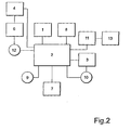
- the device comprises a manoeuvring organ 1 arranged on a panel 14 in the cabin of the vehicle, said manoeuvring organ being in the form of a button which is intended to be hand manoeuvred by a driver of the vehicle.
- panel here refers to an inner wall section of the cabin, more precisely to the instrument panel of the vehicle.
- the manoeuvring organ 1 is via a control unit 2 coupled to at least one of, and preferably all of, the brakes 3 of the vehicle, and to the gear box 4 of the vehicle. When activating the manoeuvring organ 1 (depressing the button), the brakes 3 are activated and the gear box 4 is brought to its neutral position.
- the brakes 3 are more precisely activated by means of a brake pressure determined in advance. Preferably, the pressure is activated successively until the predetermined brake pressure has been reached.
- Said gear box is preferably automatic and connected to a converter.
- An engaged gear would bring about energy losses in the form of so-called "dragging" in a non-moving vehicle. This means that said neutral position should be obtained in the gear box during dumping or loading respectively.
- the manoeuvring organ 1 is arranged in the immediate vicinity of the tilting lever 5 of the vehicle in such a way that the driver can manoeuvre the tilting lever 5 and the manoeuvring organ 1 at the same time, and with the same hand.
- the tilting lever 5 is connected to the load-carrying platform of the vehicle via hydraulic circuits (not shown) with the purpose of raising/lowering it.
- the tilting lever 5 is according to the preferred embodiment arranged on the right side of the driver so that it may be manoeuvred with the right hand.
- the manoeuvring organ 1 is arranged to be manoeuvred by the thumb of the driver while the driver has the rest of his hand available for manoeuvring the tilting lever 5.
- the manoeuvring organ 1 is a button, its activation can take place quickly by means of depressing the button, and with a relatively small diversion of attention from controlling the rest of the vehicle and the load-carrying platform, which simplifies the dumping for the driver and contributes to an improved safety.
- the device comprises an organ 12 connected to the control unit 2 for detecting manual movement of the gear lever 6.
- the organ 12 for detecting the gear lever can, for example, be a breaker.
- the device additionally comprises an organ 8 coupled to the control unit 2 for indicating that the manoeuvring organ 1 is activated, and that the brake 3 thus is activated, and that the gear box 4 is in its neutral position.
- the indication organ 8 is preferably a lamp arranged on the instrument panel. The lamp is lit when the manoeuvring organ 1 is activated, and is shut off when the brakes 3 are released.
- the device additionally comprises an organ 9 coupled to the control unit 2 for detecting the speed of the vehicle, with the purpose of maintaining said brake 3 in a non-active position and the current gear of the gear box 4, in spite of an activation of the manoeuvring organ 1 when the speed of the vehicle exceeds a predetermined speed.
- This predetermined speed is preferably in the range of 0-7 km/h.
- the speed sensing organ 9 can, for example, be a conventional speedometer.
- the device also comprises an organ 10 coupled to the control unit 2 for sensing the pressure in said brake 3.
- the control unit 2 is coupled to the parking brake 11 of the vehicle for activating it when the brake pressure falls below a predetermined value.
- a control device 13 is illustrated which is coupled to the parking brake 11 for manual control of it.
- the control unit 2 is also coupled to the engine 7 of the vehicle.
- the control unit 2 is arranged to activate the parking brake 11 if the engine is turned off or if the engine is stalled with the brakes activated and the gear box is in the neutral position.
- the control unit 2 is preferably a computer unit and comprises software for controlling said parts and functions of the device.
- the manoeuvring organ is arranged directly on the tilting lever.
- the manoeuvring organ is arranged on the steering wheel of the vehicle.
- the manoeuvring organ 1 can, as an alternative to said button, be a lever or another control means.
- manoeuvring organ 1 is arranged in a vehicle, with the instrument panel including, among other things, the tilting lever on the left side of the driver.
- the manoeuvring organ 1 is also in this case preferably arranged on the left side of the driver in connection to the tilting lever.
Landscapes
- Engineering & Computer Science (AREA)
- Transportation (AREA)
- Mechanical Engineering (AREA)
- Combustion & Propulsion (AREA)
- Chemical & Material Sciences (AREA)
- Automation & Control Theory (AREA)
- Control Of Transmission Device (AREA)
- Regulating Braking Force (AREA)
- Braking Elements And Transmission Devices (AREA)
- Vehicle Body Suspensions (AREA)
- Arrangement Or Mounting Of Control Devices For Change-Speed Gearing (AREA)
- Forklifts And Lifting Vehicles (AREA)
- Control Of Driving Devices And Active Controlling Of Vehicle (AREA)
Claims (11)
- Véhicule porteur de charge comportant une plate-forme pour porter une charge, la plate-forme pouvant être inclinée pour déverser la charge, le véhicule comportant en outre une cabine, des freins de véhicule (3), une boîte de vitesses (4), un organe de manoeuvre (1) qui est agencé dans la cabine pour une manoeuvre manuelle par un conducteur, et une unité de commande (2) qui est couplée audit organe de manoeuvre (1), à au moins un des freins (3) et à la boîte de vitesses (4)
caractérisé en ce que
ledit organe de manoeuvre (1) est agencé pour être actionné par le conducteur pour- actionner ledit frein (3), et- obtenir une position neutre dans la boîte de vitesses (4) lorsqu un déversement ou un déchargement de la plate-forme est nécessaire, et en ce que 1 unité de commande (2) est programmée pour actionner au moins un desdits freins (3) et obtenir la position neutre dans la boîte de vitesses (4) lorsque ledit organe de manoeuvre (1) est actionné par le conducteur. - Véhicule porteur de charge selon la revendication 1, caractérisé en ce que 1 organe de manoeuvre (1) est agencé d une manière telle qu il est à la portée du conducteur tandis que le conducteur manoeuvre simultanément le volant et le levier de déversement (5) du véhicule.
- Véhicule porteur de charge selon la revendication 1 ou 2, caractérisé en ce que 1 organe de manoeuvre (1) est agencé sur un panneau (14) dans la cabine, à la proximité immédiate du levier de déversement (5) du véhicule, d une manière telle qu il est à la portée du conducteur tout en manoeuvrant simultanément le levier de déversement avec la même main.
- Véhicule porteur de charge selon l'une quelconque des revendications précédentes, caractérisé en ce qu un organe (12) est connecté à 1 unité de commande (2) pour détecter un déplacement manuel d un levier de changement de vitesse (4) relié à la boîte de vitesses (6).
- Véhicule porteur de charge selon l'une quelconque des revendications précédentes, caractérisé en ce qu un organe (9) est connecté à 1 unité de commande (2) pour détecter la vitesse du véhicule, le but étant de maintenir lesdits freins (3) dans une position inactive et la présente vitesse dans la boîte de vitesses (4), en dépit d un actionnement de 1 organe de manoeuvre (1) lorsque la vitesse du véhicule dépasse une vitesse prédéterminée.
- Véhicule porteur de charge selon 1 une quelconque des revendications précédentes, caractérisé en ce qu un organe (10) est couplé à 1 unité de commande pour détecter la pression dans lesdits freins (3), et en ce que 1 unité de commande (2) est couplée à un frein de stationnement (11) du véhicule pour son actionnement lorsque la pression de frein tombe en dessous d une valeur prédéterminée.
- Véhicule porteur de charge selon l'une quelconque des revendications précédentes, caractérisé en ce que c est un tombereau commandé à la taille.
- Procédé pour manoeuvrer un véhicule porteur de charge lors d un déversement ou d un déchargement dune plate-forme porteuse de charge du véhicule, dans lequel un actionnement d un organe de manoeuvre manuelle (1) agencé dans une cabine du véhicule porteur de charge est détecté,
caractérisé en ce que- au moins un frein de véhicule (3) est actionné, et- une boîte de vitesses de véhicule (4) est amenée à prendre une position neutre lorsque 1actionnement de 1organe de manoeuvre (1) est détecté. - Procédé selon la revendication 8, caractérisé en ce qu un déplacement manuel d un levier de sélection de vitesse (6) relié à la boîte de vitesses (4) à partir de la position neutre vers une position de vitesse est détecté lorsque 1 organe de manoeuvre (1) est actionné, et en ce que lesdits freins sont ensuite libérés.
- Procédé selon la revendication 8 ou 9, caractérisé en ce que la pression dans lesdits freins (3) est détectée, et en ce quun frein de stationnement (11) du véhicule est actionné lorsque la pression de frein tombe en dessous d une valeur prédéterminée.
- Procédé selon la revendication 10, caractérisé en ce que le frein de stationnement (11) du véhicule est actionné lorsque le moteur du véhicule est arrêté ou lorsque le moteur cale si les freins (3) ont été préalablement actionnés, et la boîte de vitesses (4) a été amenée dans la position neutre via un actionnement de 1 organe de manoeuvre (1).
Applications Claiming Priority (3)
| Application Number | Priority Date | Filing Date | Title |
|---|---|---|---|
| SE0002087A SE515446C2 (sv) | 2000-06-05 | 2000-06-05 | Anordning och förfarande för styrning av specifika funktioner hos ett lastfordon vid tippning och/eller lastning av fordonets flak |
| SE0002087 | 2000-06-05 | ||
| PCT/SE2001/001231 WO2001094147A1 (fr) | 2000-06-05 | 2001-06-01 | Procede et dispositif de gestion de fonctions specifiques a l'interieur d'un vehicule de transport de charge lors du dechargement et/ou du chargement de la plateforme de transport de charge du vehicule |
Publications (2)
| Publication Number | Publication Date |
|---|---|
| EP1286850A1 EP1286850A1 (fr) | 2003-03-05 |
| EP1286850B1 true EP1286850B1 (fr) | 2006-05-17 |
Family
ID=20279964
Family Applications (1)
| Application Number | Title | Priority Date | Filing Date |
|---|---|---|---|
| EP01937103A Expired - Lifetime EP1286850B1 (fr) | 2000-06-05 | 2001-06-01 | Procede et dispositif de gestion de fonctions specifiques a l'interieur d'un vehicule de transport de charge lors du dechargement et/ou du chargement de la plateforme de transport de charge du vehicule |
Country Status (9)
| Country | Link |
|---|---|
| US (2) | US7281602B2 (fr) |
| EP (1) | EP1286850B1 (fr) |
| JP (1) | JP2003535746A (fr) |
| AT (1) | ATE326375T1 (fr) |
| AU (1) | AU6286801A (fr) |
| DE (1) | DE60119726T2 (fr) |
| SE (1) | SE515446C2 (fr) |
| WO (1) | WO2001094147A1 (fr) |
| ZA (1) | ZA200209572B (fr) |
Cited By (1)
| Publication number | Priority date | Publication date | Assignee | Title |
|---|---|---|---|---|
| WO2009008785A1 (fr) | 2007-07-11 | 2009-01-15 | Volvo Construction Equipment Ab | Procédé et dispositif de commande d'un véhicule comprenant un corps de benne basculante |
Families Citing this family (12)
| Publication number | Priority date | Publication date | Assignee | Title |
|---|---|---|---|---|
| DE20201957U1 (de) * | 2002-02-08 | 2003-06-12 | Franz Xaver Meiller Fahrzeug- und Maschinenfabrik - GmbH & Co KG, 80997 München | Kipper, insbesondere Absetzkipper |
| JP2007022135A (ja) * | 2005-07-12 | 2007-02-01 | Toyota Motor Corp | 車両の自動制動装置 |
| DE102008030656A1 (de) | 2008-07-01 | 2010-01-07 | Wabco Gmbh | Fertigerbremse |
| DE102013007955B4 (de) | 2013-05-08 | 2024-02-29 | Caterpillar Inc. | Vorrichtung zum Betätigen einer Betriebsbremse und Verriegeln einer Pendelachse eines Mobilbaggers |
| US20150323069A1 (en) * | 2014-05-09 | 2015-11-12 | Caterpillar Sarl | Braking System |
| US9625036B2 (en) | 2014-05-09 | 2017-04-18 | Caterpillar Sarl | Braking system |
| US20150323070A1 (en) * | 2014-05-09 | 2015-11-12 | Caterpillar Sarl | Braking system |
| EP2949507A1 (fr) * | 2014-05-29 | 2015-12-02 | Caterpillar SARL | Véhicule et procédé de commande d'un véhicule |
| CN104842980A (zh) * | 2015-04-29 | 2015-08-19 | 常州坤茂机械有限公司 | 一种车用手刹消毒灭菌装置 |
| US9845039B2 (en) * | 2015-09-14 | 2017-12-19 | Caterpillar Inc. | System and method of automatically operating a hoist system for a machine |
| US10196063B2 (en) * | 2017-06-19 | 2019-02-05 | GM Global Technology Operations LLC | Vehicles, systems, and methods for shifting manual transmissions into neutral during autonomous braking |
| JP7382185B2 (ja) * | 2019-09-10 | 2023-11-16 | 株式会社小松製作所 | 操作装置及び作業車両 |
Family Cites Families (18)
| Publication number | Priority date | Publication date | Assignee | Title |
|---|---|---|---|---|
| US3858696A (en) * | 1967-12-11 | 1975-01-07 | Int Harvester Co | Forward reverse drive control providing automatic braking |
| US3939937A (en) * | 1974-11-01 | 1976-02-24 | Browning-Ferris Industries, Inc. | Safety apparatus for service vehicle |
| US4088208A (en) * | 1976-10-26 | 1978-05-09 | International Harvester Company | Transmission disconnect system |
| JPS53138091U (fr) * | 1977-04-06 | 1978-11-01 | ||
| US4560148A (en) * | 1982-03-22 | 1985-12-24 | Caterpillar Tractor Co. | Log skidder vehicle brake system |
| JPS58214424A (ja) * | 1982-06-08 | 1983-12-13 | Nitsutsuu Fukuyama Tekko Unyu Kk | ダンプ車のベツセル上昇走行自動停止装置 |
| JPS6146723A (ja) * | 1984-08-11 | 1986-03-07 | Toyoda Autom Loom Works Ltd | ダンプカ−におけるダンプコントロ−ル機構 |
| JPS62258829A (ja) * | 1986-05-01 | 1987-11-11 | Sankiyuu Kk | ダンプカ−用帆立事故防止装置 |
| JPH0543319Y2 (fr) * | 1988-06-17 | 1993-11-01 | ||
| JP2694057B2 (ja) * | 1991-02-26 | 1997-12-24 | 株式会社クボタ | 作業車の走行伝動構造 |
| JP2593980Y2 (ja) * | 1991-09-05 | 1999-04-19 | 小松メック株式会社 | 駐車ブレーキ制御装置 |
| JPH07144623A (ja) * | 1993-11-24 | 1995-06-06 | Honda Motor Co Ltd | パーキングブレーキ制御装置 |
| JPH0924807A (ja) * | 1995-07-13 | 1997-01-28 | Yanmar Agricult Equip Co Ltd | 作業車輌の制動機構 |
| JPH0958426A (ja) * | 1995-08-30 | 1997-03-04 | Mitsubishi Motors Corp | 自動車の制動装置 |
| JPH1035442A (ja) * | 1996-07-23 | 1998-02-10 | Kunihisa Saito | サイドブレーキ補助システム |
| JP3521740B2 (ja) * | 1998-04-30 | 2004-04-19 | スズキ株式会社 | 自動変速機の故障診断装置 |
| JP2000219108A (ja) * | 1999-01-29 | 2000-08-08 | Fujitsu Ten Ltd | 制動装置 |
| JP2001106047A (ja) * | 1999-10-13 | 2001-04-17 | Toyota Motor Corp | 電動駐車ブレーキ装置 |
-
2000
- 2000-06-05 SE SE0002087A patent/SE515446C2/sv unknown
-
2001
- 2001-06-01 AU AU62868/01A patent/AU6286801A/en not_active Abandoned
- 2001-06-01 JP JP2002501684A patent/JP2003535746A/ja active Pending
- 2001-06-01 AT AT01937103T patent/ATE326375T1/de not_active IP Right Cessation
- 2001-06-01 DE DE60119726T patent/DE60119726T2/de not_active Expired - Lifetime
- 2001-06-01 WO PCT/SE2001/001231 patent/WO2001094147A1/fr not_active Ceased
- 2001-06-01 EP EP01937103A patent/EP1286850B1/fr not_active Expired - Lifetime
-
2002
- 2002-11-25 ZA ZA200209572A patent/ZA200209572B/en unknown
- 2002-12-05 US US10/065,972 patent/US7281602B2/en not_active Expired - Lifetime
-
2007
- 2007-02-28 US US11/680,601 patent/US20070150120A1/en not_active Abandoned
Cited By (1)
| Publication number | Priority date | Publication date | Assignee | Title |
|---|---|---|---|---|
| WO2009008785A1 (fr) | 2007-07-11 | 2009-01-15 | Volvo Construction Equipment Ab | Procédé et dispositif de commande d'un véhicule comprenant un corps de benne basculante |
Also Published As
| Publication number | Publication date |
|---|---|
| DE60119726T2 (de) | 2006-11-23 |
| AU6286801A (en) | 2001-12-17 |
| US20030111891A1 (en) | 2003-06-19 |
| SE0002087D0 (sv) | 2000-06-05 |
| EP1286850A1 (fr) | 2003-03-05 |
| JP2003535746A (ja) | 2003-12-02 |
| DE60119726D1 (de) | 2006-06-22 |
| ATE326375T1 (de) | 2006-06-15 |
| WO2001094147A1 (fr) | 2001-12-13 |
| SE0002087L (sv) | 2001-08-06 |
| US20070150120A1 (en) | 2007-06-28 |
| SE515446C2 (sv) | 2001-08-06 |
| ZA200209572B (en) | 2004-03-04 |
| US7281602B2 (en) | 2007-10-16 |
Similar Documents
| Publication | Publication Date | Title |
|---|---|---|
| US20070150120A1 (en) | Method and device for controlling specific functions within a load-carrying vehicle under dumping and/or loading the load-carrying platform of the vehicle | |
| US6910988B2 (en) | Method for reversing the driving direction | |
| US6145399A (en) | Indicator for a shift by wire vehicle transmission | |
| CN101627232A (zh) | 用于操作车辆变速箱的控制设备、用于换档和驻车制动促动的系统和包括控制设备和系统的车辆 | |
| KR101970855B1 (ko) | 작업 차량의 제어 장치 | |
| CN106458171A (zh) | 制动系统 | |
| EP2323883B1 (fr) | Procédé et système de changement de vitesse automatisé | |
| EP1524456B1 (fr) | Dispositif de commande du démarrage d'un véhicule automobile | |
| US20240326819A1 (en) | Vehicle control device and method | |
| US11879544B2 (en) | Method for avoiding activation of a sailing functionality, a transmission system and a vehicle comprising a transmission system | |
| JPH10246321A (ja) | 車両の変速装置 | |
| US7445101B2 (en) | System and method for reversing the movement of a vehicle, in particular for an agricultural tractor | |
| JP2585066Y2 (ja) | 電動atチェンジ | |
| US11167765B2 (en) | Work vehicle | |
| JP2679300B2 (ja) | 制動力保持装置 | |
| JP2006273090A (ja) | 駐車ブレーキ制御装置 | |
| JPH07101321A (ja) | 坂道発進補助装置 | |
| US20030006077A1 (en) | Apparatus and method of retarding a work machine | |
| CN106304841A (zh) | 制动系统 | |
| JPH02147732A (ja) | 建設機械の自動変速装置 | |
| KR20020096724A (ko) | 수동 변속 차량의 제동시 시동 꺼짐 방지 장치 | |
| KR19980047674A (ko) | 파킹 브레이크 자동 제어 시스템 | |
| JPH08133031A (ja) | 坂道発進補助装置 | |
| JPH01250646A (ja) | 自動変速車の発進制御装置 | |
| JPS60179556A (ja) | 車両用自動変速機 |
Legal Events
| Date | Code | Title | Description |
|---|---|---|---|
| PUAI | Public reference made under article 153(3) epc to a published international application that has entered the european phase |
Free format text: ORIGINAL CODE: 0009012 |
|
| 17P | Request for examination filed |
Effective date: 20021204 |
|
| AK | Designated contracting states |
Kind code of ref document: A1 Designated state(s): AT BE CH CY DE DK ES FI FR GB GR IE IT LI LU MC NL PT SE TR |
|
| AX | Request for extension of the european patent |
Extension state: AL LT LV MK RO SI |
|
| 17Q | First examination report despatched |
Effective date: 20030819 |
|
| GRAP | Despatch of communication of intention to grant a patent |
Free format text: ORIGINAL CODE: EPIDOSNIGR1 |
|
| RIC1 | Information provided on ipc code assigned before grant |
Ipc: B60W 10/10 00000000ALI20051124BHEP Ipc: B60W 10/18 00000000ALI20051124BHEP Ipc: B60P 1/04 19680901ALI20051124BHEP Ipc: B60W 10/04 00000000AFI20051124BHEP |
|
| GRAS | Grant fee paid |
Free format text: ORIGINAL CODE: EPIDOSNIGR3 |
|
| GRAA | (expected) grant |
Free format text: ORIGINAL CODE: 0009210 |
|
| AK | Designated contracting states |
Kind code of ref document: B1 Designated state(s): AT BE CH CY DE DK ES FI FR GB GR IE IT LI LU MC NL PT SE TR |
|
| PG25 | Lapsed in a contracting state [announced via postgrant information from national office to epo] |
Ref country code: IT Free format text: LAPSE BECAUSE OF FAILURE TO SUBMIT A TRANSLATION OF THE DESCRIPTION OR TO PAY THE FEE WITHIN THE PRESCRIBED TIME-LIMIT;WARNING: LAPSES OF ITALIAN PATENTS WITH EFFECTIVE DATE BEFORE 2007 MAY HAVE OCCURRED AT ANY TIME BEFORE 2007. THE CORRECT EFFECTIVE DATE MAY BE DIFFERENT FROM THE ONE RECORDED. Effective date: 20060517 Ref country code: NL Free format text: LAPSE BECAUSE OF FAILURE TO SUBMIT A TRANSLATION OF THE DESCRIPTION OR TO PAY THE FEE WITHIN THE PRESCRIBED TIME-LIMIT Effective date: 20060517 Ref country code: LI Free format text: LAPSE BECAUSE OF FAILURE TO SUBMIT A TRANSLATION OF THE DESCRIPTION OR TO PAY THE FEE WITHIN THE PRESCRIBED TIME-LIMIT Effective date: 20060517 Ref country code: FI Free format text: LAPSE BECAUSE OF FAILURE TO SUBMIT A TRANSLATION OF THE DESCRIPTION OR TO PAY THE FEE WITHIN THE PRESCRIBED TIME-LIMIT Effective date: 20060517 Ref country code: AT Free format text: LAPSE BECAUSE OF FAILURE TO SUBMIT A TRANSLATION OF THE DESCRIPTION OR TO PAY THE FEE WITHIN THE PRESCRIBED TIME-LIMIT Effective date: 20060517 Ref country code: BE Free format text: LAPSE BECAUSE OF FAILURE TO SUBMIT A TRANSLATION OF THE DESCRIPTION OR TO PAY THE FEE WITHIN THE PRESCRIBED TIME-LIMIT Effective date: 20060517 Ref country code: CH Free format text: LAPSE BECAUSE OF FAILURE TO SUBMIT A TRANSLATION OF THE DESCRIPTION OR TO PAY THE FEE WITHIN THE PRESCRIBED TIME-LIMIT Effective date: 20060517 |
|
| REG | Reference to a national code |
Ref country code: GB Ref legal event code: FG4D |
|
| REG | Reference to a national code |
Ref country code: CH Ref legal event code: EP |
|
| PG25 | Lapsed in a contracting state [announced via postgrant information from national office to epo] |
Ref country code: IE Free format text: LAPSE BECAUSE OF NON-PAYMENT OF DUE FEES Effective date: 20060601 |
|
| REG | Reference to a national code |
Ref country code: IE Ref legal event code: FG4D |
|
| REF | Corresponds to: |
Ref document number: 60119726 Country of ref document: DE Date of ref document: 20060622 Kind code of ref document: P |
|
| PG25 | Lapsed in a contracting state [announced via postgrant information from national office to epo] |
Ref country code: MC Free format text: LAPSE BECAUSE OF NON-PAYMENT OF DUE FEES Effective date: 20060630 |
|
| PG25 | Lapsed in a contracting state [announced via postgrant information from national office to epo] |
Ref country code: SE Free format text: LAPSE BECAUSE OF FAILURE TO SUBMIT A TRANSLATION OF THE DESCRIPTION OR TO PAY THE FEE WITHIN THE PRESCRIBED TIME-LIMIT Effective date: 20060817 Ref country code: DK Free format text: LAPSE BECAUSE OF FAILURE TO SUBMIT A TRANSLATION OF THE DESCRIPTION OR TO PAY THE FEE WITHIN THE PRESCRIBED TIME-LIMIT Effective date: 20060817 |
|
| PG25 | Lapsed in a contracting state [announced via postgrant information from national office to epo] |
Ref country code: ES Free format text: LAPSE BECAUSE OF FAILURE TO SUBMIT A TRANSLATION OF THE DESCRIPTION OR TO PAY THE FEE WITHIN THE PRESCRIBED TIME-LIMIT Effective date: 20060828 |
|
| PG25 | Lapsed in a contracting state [announced via postgrant information from national office to epo] |
Ref country code: PT Free format text: LAPSE BECAUSE OF FAILURE TO SUBMIT A TRANSLATION OF THE DESCRIPTION OR TO PAY THE FEE WITHIN THE PRESCRIBED TIME-LIMIT Effective date: 20061017 |
|
| NLV1 | Nl: lapsed or annulled due to failure to fulfill the requirements of art. 29p and 29m of the patents act | ||
| REG | Reference to a national code |
Ref country code: CH Ref legal event code: PL |
|
| ET | Fr: translation filed | ||
| PLBE | No opposition filed within time limit |
Free format text: ORIGINAL CODE: 0009261 |
|
| STAA | Information on the status of an ep patent application or granted ep patent |
Free format text: STATUS: NO OPPOSITION FILED WITHIN TIME LIMIT |
|
| 26N | No opposition filed |
Effective date: 20070220 |
|
| PG25 | Lapsed in a contracting state [announced via postgrant information from national office to epo] |
Ref country code: GR Free format text: LAPSE BECAUSE OF FAILURE TO SUBMIT A TRANSLATION OF THE DESCRIPTION OR TO PAY THE FEE WITHIN THE PRESCRIBED TIME-LIMIT Effective date: 20060818 |
|
| PG25 | Lapsed in a contracting state [announced via postgrant information from national office to epo] |
Ref country code: TR Free format text: LAPSE BECAUSE OF FAILURE TO SUBMIT A TRANSLATION OF THE DESCRIPTION OR TO PAY THE FEE WITHIN THE PRESCRIBED TIME-LIMIT Effective date: 20060517 Ref country code: LU Free format text: LAPSE BECAUSE OF NON-PAYMENT OF DUE FEES Effective date: 20060601 |
|
| PG25 | Lapsed in a contracting state [announced via postgrant information from national office to epo] |
Ref country code: CY Free format text: LAPSE BECAUSE OF FAILURE TO SUBMIT A TRANSLATION OF THE DESCRIPTION OR TO PAY THE FEE WITHIN THE PRESCRIBED TIME-LIMIT Effective date: 20060517 |
|
| PGFP | Annual fee paid to national office [announced via postgrant information from national office to epo] |
Ref country code: FR Payment date: 20080617 Year of fee payment: 8 |
|
| REG | Reference to a national code |
Ref country code: FR Ref legal event code: ST Effective date: 20100226 |
|
| PG25 | Lapsed in a contracting state [announced via postgrant information from national office to epo] |
Ref country code: FR Free format text: LAPSE BECAUSE OF NON-PAYMENT OF DUE FEES Effective date: 20090630 |
|
| PGFP | Annual fee paid to national office [announced via postgrant information from national office to epo] |
Ref country code: DE Payment date: 20160616 Year of fee payment: 16 |
|
| PGFP | Annual fee paid to national office [announced via postgrant information from national office to epo] |
Ref country code: GB Payment date: 20170629 Year of fee payment: 17 |
|
| REG | Reference to a national code |
Ref country code: DE Ref legal event code: R119 Ref document number: 60119726 Country of ref document: DE |
|
| PG25 | Lapsed in a contracting state [announced via postgrant information from national office to epo] |
Ref country code: DE Free format text: LAPSE BECAUSE OF NON-PAYMENT OF DUE FEES Effective date: 20180103 |
|
| GBPC | Gb: european patent ceased through non-payment of renewal fee |
Effective date: 20180601 |
|
| PG25 | Lapsed in a contracting state [announced via postgrant information from national office to epo] |
Ref country code: GB Free format text: LAPSE BECAUSE OF NON-PAYMENT OF DUE FEES Effective date: 20180601 |