EP1287933A2 - Méthode de fabrication de matrices d'extrusion avec des protubérances de dimensions variables - Google Patents
Méthode de fabrication de matrices d'extrusion avec des protubérances de dimensions variables Download PDFInfo
- Publication number
- EP1287933A2 EP1287933A2 EP02015680A EP02015680A EP1287933A2 EP 1287933 A2 EP1287933 A2 EP 1287933A2 EP 02015680 A EP02015680 A EP 02015680A EP 02015680 A EP02015680 A EP 02015680A EP 1287933 A2 EP1287933 A2 EP 1287933A2
- Authority
- EP
- European Patent Office
- Prior art keywords
- pins
- discharge
- array
- die
- face
- Prior art date
- Legal status (The legal status is an assumption and is not a legal conclusion. Google has not performed a legal analysis and makes no representation as to the accuracy of the status listed.)
- Withdrawn
Links
Images


Classifications
-
- B—PERFORMING OPERATIONS; TRANSPORTING
- B23—MACHINE TOOLS; METAL-WORKING NOT OTHERWISE PROVIDED FOR
- B23H—WORKING OF METAL BY THE ACTION OF A HIGH CONCENTRATION OF ELECTRIC CURRENT ON A WORKPIECE USING AN ELECTRODE WHICH TAKES THE PLACE OF A TOOL; SUCH WORKING COMBINED WITH OTHER FORMS OF WORKING OF METAL
- B23H1/00—Electrical discharge machining, i.e. removing metal with a series of rapidly recurring electrical discharges between an electrode and a workpiece in the presence of a fluid dielectric
- B23H1/04—Electrodes specially adapted therefor or their manufacture
-
- B—PERFORMING OPERATIONS; TRANSPORTING
- B23—MACHINE TOOLS; METAL-WORKING NOT OTHERWISE PROVIDED FOR
- B23H—WORKING OF METAL BY THE ACTION OF A HIGH CONCENTRATION OF ELECTRIC CURRENT ON A WORKPIECE USING AN ELECTRODE WHICH TAKES THE PLACE OF A TOOL; SUCH WORKING COMBINED WITH OTHER FORMS OF WORKING OF METAL
- B23H9/00—Machining specially adapted for treating particular metal objects or for obtaining special effects or results on metal objects
-
- B—PERFORMING OPERATIONS; TRANSPORTING
- B23—MACHINE TOOLS; METAL-WORKING NOT OTHERWISE PROVIDED FOR
- B23P—METAL-WORKING NOT OTHERWISE PROVIDED FOR; COMBINED OPERATIONS; UNIVERSAL MACHINE TOOLS
- B23P15/00—Making specific metal objects by operations not covered by a single other subclass or a group in this subclass
- B23P15/24—Making specific metal objects by operations not covered by a single other subclass or a group in this subclass dies
- B23P15/243—Honeycomb dies
-
- B—PERFORMING OPERATIONS; TRANSPORTING
- B28—WORKING CEMENT, CLAY, OR STONE
- B28B—SHAPING CLAY OR OTHER CERAMIC COMPOSITIONS; SHAPING SLAG; SHAPING MIXTURES CONTAINING CEMENTITIOUS MATERIAL, e.g. PLASTER
- B28B3/00—Producing shaped articles from the material by using presses; Presses specially adapted therefor
- B28B3/20—Producing shaped articles from the material by using presses; Presses specially adapted therefor wherein the material is extruded
- B28B3/26—Extrusion dies
- B28B3/269—For multi-channeled structures, e.g. honeycomb structures
-
- B—PERFORMING OPERATIONS; TRANSPORTING
- B29—WORKING OF PLASTICS; WORKING OF SUBSTANCES IN A PLASTIC STATE IN GENERAL
- B29C—SHAPING OR JOINING OF PLASTICS; SHAPING OF MATERIAL IN A PLASTIC STATE, NOT OTHERWISE PROVIDED FOR; AFTER-TREATMENT OF THE SHAPED PRODUCTS, e.g. REPAIRING
- B29C48/00—Extrusion moulding, i.e. expressing the moulding material through a die or nozzle which imparts the desired form; Apparatus therefor
- B29C48/03—Extrusion moulding, i.e. expressing the moulding material through a die or nozzle which imparts the desired form; Apparatus therefor characterised by the shape of the extruded material at extrusion
- B29C48/09—Articles with cross-sections having partially or fully enclosed cavities, e.g. pipes or channels
- B29C48/11—Articles with cross-sections having partially or fully enclosed cavities, e.g. pipes or channels comprising two or more partially or fully enclosed cavities, e.g. honeycomb-shaped
-
- B—PERFORMING OPERATIONS; TRANSPORTING
- B23—MACHINE TOOLS; METAL-WORKING NOT OTHERWISE PROVIDED FOR
- B23H—WORKING OF METAL BY THE ACTION OF A HIGH CONCENTRATION OF ELECTRIC CURRENT ON A WORKPIECE USING AN ELECTRODE WHICH TAKES THE PLACE OF A TOOL; SUCH WORKING COMBINED WITH OTHER FORMS OF WORKING OF METAL
- B23H2200/00—Specific machining processes or workpieces
- B23H2200/30—Specific machining processes or workpieces for making honeycomb structures
-
- B—PERFORMING OPERATIONS; TRANSPORTING
- B29—WORKING OF PLASTICS; WORKING OF SUBSTANCES IN A PLASTIC STATE IN GENERAL
- B29L—INDEXING SCHEME ASSOCIATED WITH SUBCLASS B29C, RELATING TO PARTICULAR ARTICLES
- B29L2031/00—Other particular articles
- B29L2031/60—Multitubular or multicompartmented articles, e.g. honeycomb
Definitions
- the present invention relates to a extrusion dies for the extrusion of honeycomb structures from plasticized organic or inorganic batch materials.
- the present invention relates to extrusion dies with varying pin size.
- Conventional extrusion dies for honeycomb extrusion comprise a feed or inlet section, provided with a plurality of feedholes for the input of extrudable material to the die, and a discharge section connecting with the feed section for reforming and discharging the extrudable material form a discharge face of the die.
- the material is reformed into a honeycomb shape comprising a plurality of open-ended channels, equal in cross-section and bounded by interconnecting cell wall extending from one end of the structure to another in the direction of extrusion.
- the discharge opening in the discharge face of these dies may be configured to form any of a variety of shapes for the interconnecting honeycomb wall structure.
- the discharge openings used for the extrusion of commercial ceramic honeycombs for treating automotive and diesel exhaust gases are formed by a criss-crossing array of long straight discharge slots of equal spacing. These long slots intersect to form a network of shorter slot segments for the forming of straight wall for square- or triangular- celled honeycombs.
- Extrudable material processed through these commercial dies must follow a complex flow path.
- the material first moves from each feedhole through a transition zone into the base of the slot array, where it flows laterally to join with material from adjacent feedholes. Thereafter, the knitted material is again directed forwardly in the direction of feedhole flow toward the discharge opening formed by the slots, being discharged therefrom in the form of an array of interconnecting "webs" or wall portions forming the channel walls of the honeycomb.
- honeycomb structures with alternating channel diameters have generated interest for diesel filtration applications due to lower pressure drops across the length of the structure and increased resistance to damage during the required filter regeneration cycling.
- the object of the present invention is directed at providing a die fabrication method wherein a honeycomb extrusion die incorporating a discharge face pin array of invariant square or rectangular pin size and shape is modified by electrical discharge machining (EDM) to convert the array to one of alternating pin size.
- EDM electrical discharge machining
- the EDM method employed, referred to as plunge EDM, involves removing material from the sides of alternating pins in the array using an electrical discharge electrode of tabbed shape.
- the invention relates to a method of making a honeycomb extrusion die by a) providing a die body incorporating an inlet face, a discharge face opposite the inlet face, a plurality of feedholes extending from the inlet face into the body, and an intersecting array of discharge slots extending into the body from the discharge face to connect with the feed holes at feed hole intersections within the die, the intersecting array of discharge slots being formed by side surfaces of an array of pins; b) providing an electrical discharge electrode of equal size to the die body and comprising multiple rows of parallel-aligned tabs; c) bringing the electrical discharge electrode into contact with the array of pins on the discharge face of the die body; and, d) reducing alternate pins symmetrically in size by plunge electrical discharge machining to form an array of pins varying in size on the discharge face of the die body.
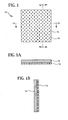
- Fig. 1 illustrates a schematic top plan, an end cross-sectional elevation (Fig. 1A) and side cross-sectional elevation (Fig. 1B) views of a comb EDM electrode according to the present invention
- Fig. 2 illustrates the die machining process according the present invention
- Fig. 3 illustrates a top cross-sectional view of a die pin array in contact with comb EDM electrode
- Fig. 4 illustrates a pin array in a die according to the present invention.
- the plunge EDM method is carried out using a comb electrical discharge electrode (hereinafter referred to as comb electrode) wherein arrays of tabs effect the removal of material from the sides of many or all of an array of square discharge pins on an extrusion die face in one machining pass.
- comb electrode comb electrical discharge electrode
- FIG. 1 therein illustrated is a schematic top plan, end and side cross-sectional elevational views of the comb electrode used in the present invention but not in true proportion or to scale.
- a suitable method of forming the comb electrode is from a stainless steel blank by traveling wire electrical discharge machining (wire EDM), as known in the art.
- Another suitable forming method would be by cutting single combs which are then assembled with spacers. This would be easier to manufacture, but more difficult to maintain fine tolerances.
- the extrusion die includes a die body incorporating an inlet face, a discharge face opposite the inlet face, a plurality of feedholes extending from the inlet face into the body, and an intersecting array of discharge slots extending into the body from the discharge face to connect with the feed holes at the feed hole/slot intersections within the die, the intersecting array of discharge slots being formed by side surfaces of an array of pins. Therefore, the comb electrode is formed the size of the die to keep manufacturing costs down.
- comb electrode 10 comprises multiple rows of parallel-aligned tabs 12 disposed on an electrode base plate 14 .
- the spacings of tabs 12 on comb electrode 10 will be set in accordance with the pin spacings on the extrusion die to be modified.
- the spacing of tabs 12 in the tab rows running parallel to the direction of tab alignment (vertically in the top plan view) will be set to be the same as the spacing between the slots on the extrusion die to be modified, so that each slot can be machined by a row of tabs at the same time.
- the tab rows running transversely to the direction of tab alignment (horizontally in the top plan view), shown in the cross-sectional side elevational view (Fig. 1A) of comb electrode 10, will be spaced so that only alternate pins along each row of tabs will be machined.
- FIG. 2 The manner in which electrode 10 intersects the pin array on the discharge face of a conventional honeycomb extrusion die during the machining process is schematically illustrated in Fig. 2 of the drawings.
- electrode 10 is being lowered into an array of pins 22 disposed on the discharge face of an extrusion die (not shown) so that tabs 12 will remove pin material 22x from the sides of pins 22a without removing material from the sides of alternate pins 22b.
- the cross-section of each of pins 22a will be reduced in one of its two cross-sectional dimensions when electrode 10 is fully engaged with pins 12a , while pins 12b will remain unaffected.
- electrode 10 will be rotated 90°, 180° and 270° and applied to the pin array in three additional steps so that tabs 12 can remove side material from the three remaining sides of pins 22a .
- the material 22x to be removed from pins 22a in the course of completing these additional steps is illustrated in the top cross-sectional view of pin array 22 shown in Fig. 3 of the drawings.
- the net result is that each of pins 22a is symmetrically reduced in size, each of pins 22b retain their original size, and the width of the slots 24 separating pins 22a and 22b on the discharge face of the die is effectively increased, whereas pins 22a have a cross-sectional area less than the cross-sectional area of pins 22b.
- Pins 22a and 22b form a checkerboard pattern of alternating small and large pins.
- the pin machining process employed does not alter the inlet or feedhole section of the die in any way, nor is any change to the inlet section of the die required.
- Fig. 4 is an illustration of a die discharge face and pin array made according to the process of the present invention.
- the geometry of an extruded ceramic filter body produced from a machined die of this design has alternating large and small cell channels.
- a section of a standard honeycomb extrusion die for the extrusion of a 200 cells/in 2 ceramic honeycomb having a channel wall thickness of 0.014 inches (a so-called 200/12 honeycomb) is selected for machining.
- the discharge face of that die includes approximately 200 pins per square inch of discharge face area, with the discharge slots separating the pins having an approximate width of 0.014 inches (0.35 mm).
- every other pin in a checkerboard pattern on the face of the die is reduced in size by 0.006 inches on each of the four sides of the pin.
- the result of the machining process is a modified extrusion die with the same 200 per square inch pin count on the die discharge face, but with a nominal slot width of 0.020 inches.
- the resulting modified extrusion die incorporates pins of two different cross sectional areas forming a checkerboard matrix.
Landscapes
- Engineering & Computer Science (AREA)
- Mechanical Engineering (AREA)
- Manufacturing & Machinery (AREA)
- Chemical & Material Sciences (AREA)
- Ceramic Engineering (AREA)
- Physics & Mathematics (AREA)
- Thermal Sciences (AREA)
- Electrical Discharge Machining, Electrochemical Machining, And Combined Machining (AREA)
- Press-Shaping Or Shaping Using Conveyers (AREA)
Applications Claiming Priority (2)
| Application Number | Priority Date | Filing Date | Title |
|---|---|---|---|
| US943464 | 1986-12-19 | ||
| US09/943,464 US6570119B2 (en) | 2001-08-30 | 2001-08-30 | Method of making extrusion die with varying pin size |
Publications (2)
| Publication Number | Publication Date |
|---|---|
| EP1287933A2 true EP1287933A2 (fr) | 2003-03-05 |
| EP1287933A3 EP1287933A3 (fr) | 2005-02-09 |
Family
ID=25479710
Family Applications (1)
| Application Number | Title | Priority Date | Filing Date |
|---|---|---|---|
| EP02015680A Withdrawn EP1287933A3 (fr) | 2001-08-30 | 2002-07-17 | Méthode de fabrication de matrices d'extrusion avec des protubérances de dimensions variables |
Country Status (3)
| Country | Link |
|---|---|
| US (1) | US6570119B2 (fr) |
| EP (1) | EP1287933A3 (fr) |
| JP (1) | JP2003071638A (fr) |
Cited By (5)
| Publication number | Priority date | Publication date | Assignee | Title |
|---|---|---|---|---|
| WO2009108336A1 (fr) * | 2008-02-28 | 2009-09-03 | Corning Incorporated | Matrices pour fabriquer des substrats et procédés de fabrication de matrice |
| EP2368681A3 (fr) * | 2010-03-23 | 2014-01-15 | NGK Insulators, Ltd. | Procédé pour la fabrication d'une filière de structure en nid d'abeille |
| CN108247156A (zh) * | 2017-12-27 | 2018-07-06 | 中核北方核燃料元件有限公司 | 一种环形燃料组件防异物网加工电化学腐蚀方法 |
| CN108620700A (zh) * | 2018-05-10 | 2018-10-09 | 广东工业大学 | 一种双面同步电解加工阵列微沟槽的装置及方法 |
| CN108857265A (zh) * | 2017-05-12 | 2018-11-23 | 帅钢模架(苏州)有限公司 | 一种标模加工工艺流程 |
Families Citing this family (13)
| Publication number | Priority date | Publication date | Assignee | Title |
|---|---|---|---|---|
| US7601194B2 (en) * | 2003-09-25 | 2009-10-13 | Corning Incorporated | Asymmetric honeycomb wall-flow filter having improved structural strength |
| US7247184B2 (en) * | 2003-09-25 | 2007-07-24 | Corning Incorporated | Asymmetric honeycomb wall-flow filter having improved structural strength |
| CN100450703C (zh) * | 2004-08-26 | 2009-01-14 | 台达电子工业股份有限公司 | 模制成型方法 |
| US8030591B2 (en) | 2006-07-31 | 2011-10-04 | 3M Innovative Properties Company | Microreplication on a complex surface |
| EP2269790B1 (fr) * | 2008-03-28 | 2015-01-21 | Hitachi Metals, Ltd. | Moule pour former une structure en nid d'abeilles céramique |
| US8244497B2 (en) * | 2009-05-29 | 2012-08-14 | Corning Incorporated | Method of solving a process function for manufacturing an extrusion die |
| US8232205B2 (en) * | 2009-08-25 | 2012-07-31 | Corning Incorporated | Methods of manufacturing a honeycomb extrusion die |
| US8263895B2 (en) * | 2009-08-28 | 2012-09-11 | Corning Incorporated | Electro-discharge electrode and method of use |
| JP5097234B2 (ja) * | 2010-03-23 | 2012-12-12 | 日本碍子株式会社 | ハニカム構造体成形用口金の製造方法 |
| JP2012125883A (ja) * | 2010-12-15 | 2012-07-05 | Ngk Insulators Ltd | ハニカム構造体成形口金用電極の製造方法 |
| CN102357689A (zh) * | 2011-09-13 | 2012-02-22 | 南京航空航天大学 | 电解加工阵列电极 |
| WO2016085782A1 (fr) | 2014-11-26 | 2016-06-02 | Corning Incorporated | Appareil et procédé pour réaliser des filières d'extrusion |
| US11135740B2 (en) | 2015-03-06 | 2021-10-05 | Corning Incorporated | Extrusion dies and methods and apparatuses for forming the same |
Family Cites Families (13)
| Publication number | Priority date | Publication date | Assignee | Title |
|---|---|---|---|---|
| JPS54150406A (en) | 1978-05-18 | 1979-11-26 | Nippon Soken | Ceramic honeycomb structure |
| US4416676A (en) | 1982-02-22 | 1983-11-22 | Corning Glass Works | Honeycomb filter and method of making it |
| US4420316A (en) | 1982-02-22 | 1983-12-13 | Corning Glass Works | Filter apparatus and method of making it |
| JPS6328523A (ja) | 1986-07-16 | 1988-02-06 | Ngk Insulators Ltd | ハニカム・ダイスの製造方法 |
| JPS6328522A (ja) | 1986-07-16 | 1988-02-06 | Ngk Insulators Ltd | ハニカム・ダイスの製造方法 |
| JPH0714574B2 (ja) | 1986-07-16 | 1995-02-22 | 日本碍子株式会社 | ハニカム・ダイス成形用放電加工電極の製造方法 |
| JP2675071B2 (ja) | 1988-05-31 | 1997-11-12 | イビデン株式会社 | ハニカム状フィルター |
| JP2502144B2 (ja) * | 1989-03-20 | 1996-05-29 | 日本碍子株式会社 | ハニカム・ダイス成形用放電加工電極の製造方法及びハニカム・ダイスの製造方法 |
| US5630951A (en) | 1995-05-15 | 1997-05-20 | Corning Incorporated | Methods and apparatus for making honeycomb extrusion dies |
| JP3080563B2 (ja) * | 1995-08-21 | 2000-08-28 | 日本碍子株式会社 | ハニカム構造体押出用ダイスの製造方法 |
| US5761787A (en) | 1995-11-30 | 1998-06-09 | Corning Incorporated | Method of making bonded pin extrusion die |
| US6290837B1 (en) * | 1997-06-09 | 2001-09-18 | Denso Corporation | Method for machining slots in molding die |
| US6448530B1 (en) * | 1998-05-11 | 2002-09-10 | Denso Corporation | Metal mold for molding a honeycomb structure and method of producing the same |
-
2001
- 2001-08-30 US US09/943,464 patent/US6570119B2/en not_active Expired - Fee Related
-
2002
- 2002-07-17 EP EP02015680A patent/EP1287933A3/fr not_active Withdrawn
- 2002-07-30 JP JP2002220717A patent/JP2003071638A/ja not_active Withdrawn
Cited By (5)
| Publication number | Priority date | Publication date | Assignee | Title |
|---|---|---|---|---|
| WO2009108336A1 (fr) * | 2008-02-28 | 2009-09-03 | Corning Incorporated | Matrices pour fabriquer des substrats et procédés de fabrication de matrice |
| EP2368681A3 (fr) * | 2010-03-23 | 2014-01-15 | NGK Insulators, Ltd. | Procédé pour la fabrication d'une filière de structure en nid d'abeille |
| CN108857265A (zh) * | 2017-05-12 | 2018-11-23 | 帅钢模架(苏州)有限公司 | 一种标模加工工艺流程 |
| CN108247156A (zh) * | 2017-12-27 | 2018-07-06 | 中核北方核燃料元件有限公司 | 一种环形燃料组件防异物网加工电化学腐蚀方法 |
| CN108620700A (zh) * | 2018-05-10 | 2018-10-09 | 广东工业大学 | 一种双面同步电解加工阵列微沟槽的装置及方法 |
Also Published As
| Publication number | Publication date |
|---|---|
| US20030042229A1 (en) | 2003-03-06 |
| EP1287933A3 (fr) | 2005-02-09 |
| US6570119B2 (en) | 2003-05-27 |
| JP2003071638A (ja) | 2003-03-12 |
Similar Documents
| Publication | Publication Date | Title |
|---|---|---|
| US6570119B2 (en) | Method of making extrusion die with varying pin size | |
| US4812276A (en) | Stepwise formation of channel walls in honeycomb structures | |
| US4846657A (en) | Die for extruding ultrafine honeycomb structures | |
| US4747986A (en) | Die and method for forming honeycomb structures | |
| EP1594687B1 (fr) | Corps alveolaire ceramique et procede de fabrication | |
| US7247184B2 (en) | Asymmetric honeycomb wall-flow filter having improved structural strength | |
| EP0250166B1 (fr) | Filière d'extrusion pour la fabrication de structures céramiques en nid d'abeilles à ailettes | |
| EP0307073B1 (fr) | Matrice à extrusion pour saillies et/ou corps en nid d'abeilles à grande densité d'alvéoles | |
| US20110206896A1 (en) | Ceramic Honeycomb Body And Process For Manufacture | |
| EP0570698B1 (fr) | Matrice d'extrusion en plusieurs parties | |
| EP0315292B1 (fr) | Filière de boudineuse pour l'extrusion de corps alvéolaires à paroi mince | |
| US6290837B1 (en) | Method for machining slots in molding die | |
| US4743191A (en) | Multi-piece die for forming honeycomb structures | |
| EP0120716B1 (fr) | Matrice d'extrusion | |
| KR20010015742A (ko) | 변형된 슬롯을 가진 압출다이 | |
| US20050274097A1 (en) | Diesel particulate filter with filleted corners | |
| US4468366A (en) | Baffled laminated extrusion dies | |
| EP0357271B1 (fr) | Filière de boudineuse | |
| US6343923B1 (en) | Cellular extrusion die | |
| US5171503A (en) | Method of extruding thin-walled honeycomb structures | |
| US6317960B1 (en) | Extrusion die and method of forming | |
| EP2465630B1 (fr) | Electrode pour la fabrication d'une filière d'extrusion pour mouler des structures alvéolées. | |
| US7162787B2 (en) | Method for constructing a honeycomb extrusion die | |
| JP4332289B2 (ja) | 六角セルハニカム押出金型の製造方法 | |
| JP2643338B2 (ja) | ハニカム成形用ダイスの製造方法 |
Legal Events
| Date | Code | Title | Description |
|---|---|---|---|
| PUAI | Public reference made under article 153(3) epc to a published international application that has entered the european phase |
Free format text: ORIGINAL CODE: 0009012 |
|
| AK | Designated contracting states |
Kind code of ref document: A2 Designated state(s): AT BE BG CH CY CZ DE DK EE ES FI FR GB GR IE IT LI LU MC NL PT SE SK TR Designated state(s): AT BE BG CH CY CZ DE DK EE ES FI FR GB GR IE IT LI LU MC NL PT SE SK TR |
|
| AX | Request for extension of the european patent |
Extension state: AL LT LV MK RO SI |
|
| PUAL | Search report despatched |
Free format text: ORIGINAL CODE: 0009013 |
|
| AK | Designated contracting states |
Kind code of ref document: A3 Designated state(s): AT BE BG CH CY CZ DE DK EE ES FI FR GB GR IE IT LI LU MC NL PT SE SK TR |
|
| AX | Request for extension of the european patent |
Extension state: AL LT LV MK RO SI |
|
| 17P | Request for examination filed |
Effective date: 20050513 |
|
| AKX | Designation fees paid |
Designated state(s): BE DE FR GB |
|
| 17Q | First examination report despatched |
Effective date: 20070212 |
|
| STAA | Information on the status of an ep patent application or granted ep patent |
Free format text: STATUS: THE APPLICATION IS DEEMED TO BE WITHDRAWN |
|
| 18D | Application deemed to be withdrawn |
Effective date: 20070623 |