EP1287992A2 - Tintenstrahldruckvorrichtung und Tintenstrahldruckverfahren - Google Patents
Tintenstrahldruckvorrichtung und Tintenstrahldruckverfahren Download PDFInfo
- Publication number
- EP1287992A2 EP1287992A2 EP02018958A EP02018958A EP1287992A2 EP 1287992 A2 EP1287992 A2 EP 1287992A2 EP 02018958 A EP02018958 A EP 02018958A EP 02018958 A EP02018958 A EP 02018958A EP 1287992 A2 EP1287992 A2 EP 1287992A2
- Authority
- EP
- European Patent Office
- Prior art keywords
- printing
- printing head
- ink
- head
- ink jet
- Prior art date
- Legal status (The legal status is an assumption and is not a legal conclusion. Google has not performed a legal analysis and makes no representation as to the accuracy of the status listed.)
- Granted
Links
- 238000007641 inkjet printing Methods 0.000 title claims abstract description 23
- 238000000034 method Methods 0.000 title claims abstract description 10
- 238000007639 printing Methods 0.000 claims abstract description 143
- 230000003116 impacting effect Effects 0.000 description 12
- 238000010586 diagram Methods 0.000 description 7
- 239000013598 vector Substances 0.000 description 6
- 230000002194 synthesizing effect Effects 0.000 description 4
- 230000007423 decrease Effects 0.000 description 2
- 238000012986 modification Methods 0.000 description 2
- 230000004048 modification Effects 0.000 description 2
- 230000000630 rising effect Effects 0.000 description 2
- 230000001133 acceleration Effects 0.000 description 1
- 238000009835 boiling Methods 0.000 description 1
- 230000005587 bubbling Effects 0.000 description 1
- 238000006243 chemical reaction Methods 0.000 description 1
- 239000003086 colorant Substances 0.000 description 1
- 230000006835 compression Effects 0.000 description 1
- 238000007906 compression Methods 0.000 description 1
- 238000010276 construction Methods 0.000 description 1
- 230000006837 decompression Effects 0.000 description 1
- 230000003247 decreasing effect Effects 0.000 description 1
- 230000001934 delay Effects 0.000 description 1
- 230000003111 delayed effect Effects 0.000 description 1
- 230000000694 effects Effects 0.000 description 1
- 239000004519 grease Substances 0.000 description 1
- 239000000314 lubricant Substances 0.000 description 1
- 239000002985 plastic film Substances 0.000 description 1
Images


Classifications
-
- B—PERFORMING OPERATIONS; TRANSPORTING
- B41—PRINTING; LINING MACHINES; TYPEWRITERS; STAMPS
- B41J—TYPEWRITERS; SELECTIVE PRINTING MECHANISMS, i.e. MECHANISMS PRINTING OTHERWISE THAN FROM A FORME; CORRECTION OF TYPOGRAPHICAL ERRORS
- B41J2/00—Typewriters or selective printing mechanisms characterised by the printing or marking process for which they are designed
- B41J2/005—Typewriters or selective printing mechanisms characterised by the printing or marking process for which they are designed characterised by bringing liquid or particles selectively into contact with a printing material
- B41J2/01—Ink jet
-
- B—PERFORMING OPERATIONS; TRANSPORTING
- B41—PRINTING; LINING MACHINES; TYPEWRITERS; STAMPS
- B41J—TYPEWRITERS; SELECTIVE PRINTING MECHANISMS, i.e. MECHANISMS PRINTING OTHERWISE THAN FROM A FORME; CORRECTION OF TYPOGRAPHICAL ERRORS
- B41J19/00—Character- or line-spacing mechanisms
- B41J19/18—Character-spacing or back-spacing mechanisms; Carriage return or release devices therefor
- B41J19/20—Positive-feed character-spacing mechanisms
- B41J19/202—Drive control means for carriage movement
Definitions
- the present invention relates to an ink jet printing apparatus and method that uses a printing head capable of ejecting ink to print an image on a printing medium.
- Ink jet printing apparatuses are widely used as means installed in printers, facsimile machines, or copiers to print images (including characters and symbols) on printing medium such as paper or thin plastic sheet (OHP and the like) and the like on the basis of image information.
- Fig. 6 is a perspective view of an essential part of an ink jet printing apparatus.
- a printing medium 201 is supported by a printing medium feeding roller 202 arranged in a print area.
- the feeding roller 202 is driven by a sheet feeding motor 203 to transport the printing medium 201 in a sub-scanning direction indicated by an arrow ⁇ .
- the sheet feeding motor 203 is composed of a stepping motor or a DC motor. In recent years, the DC motor is often used owing to its quietness or the like.
- a rotary encoder (not shown) is installed in the feeding roller 202 so as to control the sheet feeding motor 203 on the basis of an encoder signal obtained from the rotary encoder.
- a shaft 204 is provided in front of and parallel with the feeding roller 202.
- a carriage 205 is movably guided along the shaft 204, and is reciprocated in a main-scanning direction indicated by an arrow ⁇ , in response to a power from a carriage motor 206.
- a lubricant such as grease is provided between the shaft 204 and the carriage 204 to reduce the mechanical loads caused by friction or the like.
- the carriage motor 206 is composed of a stepping motor or a DC motor similarly to the sheet feeding motor 203. In recent years, the DC motor is often used owing to its quietness or the like.
- a rotary encoder (not shown) is arranged on the carriage 205, and a linear encoder (not shown) is arranged parallel with the shaft 204. Then, on the basis of a signal obtained from this linear encoder, the carriage motor 206 is controlled. Further, on the basis of a signal obtained from this linear encoder, timings are generated with which ink is ejected from a printing head 208.
- the carriage 205 as printing head moving means has the printing head 208 and a tank 209 mounted thereon, the tank 209 contains print ink.
- the printing head is used for printing color images and has a black ink ejecting head 208-BK, a cyan ink ejecting head 208-C, a magenta ink ejecting head 208-M, and a yellow ink ejecting head 208-Y arranged along a scanning direction of the carriage 205.
- the carriage 205 has a tank 209-BK for black ink (Bk), a tank 209-C for cyan ink(C), a tank 209-M for magenta ink (M), and a tank 209-Y for yellow ink(Y) mounted thereon as the tank 209.
- These tanks supply ink to the heads for the corresponding colors.
- the printing head 209 is provided with an ink ejecting section on a front surface thereof. The front surface is located opposite a printing surface of the printing medium 201 at a predetermined interval (for example, 0.8 mm).
- the ink ejecting section has a plurality of (for example, 48 or 64) ink ejecting ports arranged in a longitudinal line along a direction crossing the scanning direction of the carriage 205.
- a control section (not shown) of the printing apparatus including a control circuit (CPU or ASIC) and a ROM, a RAM, and the like annexed to the control circuit, for example, receives information on print modes and print data from a controller of an external host apparatus via an interface. Then, the control section of the printing apparatus controls the printing head 208 via a head drive circuit together with drive sources of the printing apparatus such as various motors, to cause ink to be ejected through the ink ejecting section of the printing head 208 to print an image on the printing medium 201.
- an image is printed on the printing medium 201 by alternately repeating an operation of ejecting ink from the ink ejecting section while moving the printing head 208 in the main-scanning direction and an operation of transporting the printing medium 201 in the sub-scanning direction by a predetermined amount.
- Fig. 7 is a diagram illustrating the relationship between the speed at which the printing head 208 is moved and the positions at which ink droplets impact the printing medium 201.
- the printing head 208 is mounted on the carriage 205 and is being moved at an ideal head speed V in the main scanning direction, indicated by ⁇ in the figure.
- an ink droplet 303 is ejected from the printing head 208 to the printing medium 201 at an ink ejection speed Vd, it flies at a speed determined by synthesizing the vectors of the ideal head speed V and ink ejection speed Vd in a direction determined in the same manner. Then, the ink droplet 303 moves the distance d between the printing head 208 and the printing medium 201 and then impacts an ideal impacting position 306 on the printing medium 201.
- the direction and speed of the ink droplet 303 vary to cause the impacting position on the printing medium 201 to deviate from the ideal impacting position 306.
- the ink droplet 303 flies at a speed determined by synthesizing the vectors of the speed Vs and ink ejection speed Vd in a direction determined in the same manner.
- the ink droplet 303 impacts the printing medium at a position located front the ideal impacting position 306.
- the ink droplet 303 flies at a speed determined by synthesizing the vectors of the speed Vf and ink ejection speed Vd in a direction determined in the same manner.
- the ink droplet 303 impacts the printing medium at a position located beyond the ideal impacting position 306.
- an ink jet printing apparatus using a printing head capable of ejecting ink and printing a printing medium by ejecting ink while moving the printing head and the printing medium relative to each other, the apparatus characterized by comprising:
- an ink jet printing method of using a printing head capable of ejecting ink and printing a printing medium by ejecting ink while moving the printing head and the printing medium relative to each other the method characterized by comprising the steps of:
- the present invention enables ink to always impact a printing medium at an ideal position by adjusting ink ejection timings according to the moving speed of the printing head. As a result, a high-grade image can be printed without being affected by a variation in moving speed of the printing head.
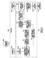
- Fig. 1 is a block diagram of the printing apparatus in this example.
- Print data transferred from a host apparatus 101 is received by an I/F section 103 in a print control section 102 of the printing apparatus in this example and is then transmitted to a print data generating section 104.
- the print data generating section 104 carries out decompression of compressed data, conversion of a data arrangement, and the like to convert the received data into a format that can be printed by a printing head 208.
- the printing head 208 may be, for example, an ink jet printing head of a type that ejects ink using thermal energy.
- the ink jet printing head causes film boiling in ink in an ink channel using thermal energy generated by electrothermal converter provided the in the ink channel. The resulting bubbling energy is used to eject ink droplet through ink ejecting port.
- a carriage 205 driven by a carriage motor 206 has the printing head 208 and an encoder 109 mounted thereon.
- the encoder 109 outputs a pulse signal each time the carriage 205 is moved a specified distance.
- a pulse signal generated by the encoder 109 passes through an LPF section 110 in a print control section 102.
- the pulse signal is deprived of noise and then transmitted to an edge trigger generating section 111.
- the edge trigger generating section 111 detects predetermined edges (encoder edges) in the received pulse signal to generate trigger pulses.
- the trigger pulses generated by the edge trigger generating section 111 are transmitted to a speed detecting section 112 and an edge trigger delay section 113.
- the speed detecting section 112 measures the interval between the trigger pulses generated by the edge trigger generating section 111, and transfers the corresponding value to a delay value calculating section 114 as the current speed information. Further, the speed information detected by the speed detecting section 112 is also transmitted to a servo controller (not shown) that servo-controls the carriage motor 206, as required.
- the delay value calculating section 114 uses the current speed information and the like transmitted by the speed detecting section 112 to calculate an impact correction delay value required to correct the ink droplet impacting position as described later.
- the edge trigger delay section 113 delays the trigger pulses generated by the edge trigger generating section 111 according to the impact correction delay value calculated by the delay value calculating section 114. Then, the edge trigger delay section 113 outputs the trigger pulses to a print timing generating section 115.
- the print timing generating section 115 generates a print timing signal by converting the trigger pulses transmitted by the edge trigger delay section 113 into print resolutions. Then, the print timing generating section 115 transmits the print timing signal to a print data transferring section 106 and a position detecting section 116.
- the position detecting section 116 uses an up/down counter to count the signals transmitted from the edge trigger delay section 113 and print timing generating section 115, thereby detecting the moving position of the carriage 205.
- the position information detected by the position detecting section 116 is transmitted to a print position detecting section 117.
- the print position detecting section 117 generates a print start signal when a print start position is detected in the position information, while generating a print end signal when a print end position is detected therein. Then, the print position detecting section 117 transmits this signal to the print data transferring section 106.
- the print data transferring section 106 transfers print data generated by the print data generating section 104 to the printing head 208 according to the information from the print timing generating section 115 and print position detecting section 117. On the basis of the information transmitted from the print data transferring section 106, the printing head 208 ejects the ink droplet to the printing medium 201.
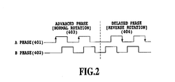
- Fig. 2 shows the waveforms of signals (encoder signals) generated by the encoder 109.
- Signals generated by the encoder 109 have two waveforms with an A phase 401 and a B phase 402 which deviate from each other through about 90° as in the case with general digital encoder signals.
- an advanced phase (normal rotation) 403, shown in the left of Fig. 2, or a delayed phase (reverse rotation) 404, shown in the right of Fig. 2 is obtained depending on the movement direction of the carriage 205.
- the moving position of the carriage 205 can be detected by, for example, using one-side edges of the A phase as detected points to switch an up/down operation of a position detecting counter at rising and falling edges of the A phase with the B phase fixed at a certain level (in the figure, a low level).
- the up/down operation of the position detecting counter is switched so that the position detecting counter performs a count up operation each time a rising edge is detected in the A phase, whereas it performs a count down operation each time a falling edge is detected. Then, the moving position of the carriage 205 (the moving position of the printing head 208) can be detected from the count value of the position detecting counter.
- the edge trigger generating section 111 detects edges of encoder pulses as shown in Fig. 2 to generate trigger pulses.
- the speed detecting section 112 measures the interval (time) (also referred to as the "encoder edge interval (time)") between the trigger pulses to detect the moving speed of the carriage 205.
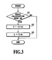
- Fig. 3 is a flow chart illustrating a basic calculating operation performed by the delay value calculating section 114.
- t1 denotes the current encoder edge interval (time), which corresponds to the current speed of the carriage 205 (the current speed of the printing head 208).
- t2 denotes the encoder edge interval (time) at the expected maximum speed, which corresponds to the maximum speed of the carriage 205 (the maximum speed of the printing head 208).
- Y denotes the result of the calculation (t1 - t2), and
- A denotes the constant of the value (t3/t2).
- t3 denotes the time required for the ink droplet 303 ejected from the printing head 208 to impact the printing medium 201.
- t denotes an impact correction delay value as the result of a calculation executed by the delay value calculating section 114.
- the expected maximum speed is a virtual speed which is higher than a speed achieved by scanning of the carriage. It is advantageous to set the maximum speed to be higher than the speed achieved by scanning of the carriage.
- the delay value increases as the maximum speed is set to be higher. Therefore, if the set maximum speed is too high, the delay value exceeds one period of the encoder signal, thus the requiring circuit and the like which holds the delay value until the next period of the encoder signal. Accordingly, it is desirable that the maximum speed be higher than the speed achieved by scanning of the carriage, and be set within the range such that the delay value does not exceed such one period of the encoder signal.
- the value t decreases with increasing current speed of the carriage 205 and consistently with the encoder edge interval t1. Conversely, the value t increases with decreasing current speed of the carriage 205 and consistently with the encoder edge interval t1.
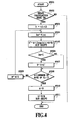
- Fig. 4 is a flow chart illustrating a more specific calculating operation performed by the delay value calculating section 114.
- Y(n) in Fig. 4 is the value of the n-th bit of the value Y as expressed by binary notation.
- steps S504 to S507 are repeated until the value n reaches ⁇ (the number of bits of the value Y) - 1 ⁇ . The number of the repetitions equals the number of bits of the value Y.
- steps S504 to S507 are repeated as many times as the number of bits of the value Y. Then. the value n is reset to 0 (S510), and the calculation (Y/B) is executed to determine the impact correction delay value t (S511). Since the value B is the power of 2, the least significant bits of the value Y as expressed by binary notation may actually be rounded off by bit shifting. As a result, the impact correction delay value t is determined by Equation (2), shown above.
- the impact correction delay value t calculated by the delay value calculating section 114, is transmitted to the edge trigger delay section 113 (see Fig. 1). Then, print timings are adjusted according to the impact correction delay value t.
- Fig. 5 is a diagram illustrating the relationship between print timings and an ink droplet impacting position.
- the edge trigger generating section 111 uses an encoder signal 601 to generate an encoder position trigger 602 as a position management signal for the printing head 208. If high-resolution printing is carried out, triggers are generated which have a period equal to half or quarter the period of the encoder signal. For example, if the period of the encoder signal corresponds to a resolution of 300 dpi, a print resolution of 600 dpi is obtained using triggers having a period equal to half the period of the encoder signal. Further, a print resolution of 1,200 dpi is obtained using triggers having a period equal to quarter the period of the encoder signal. In Fig.
- the ink droplet 303 flies in the direction of a vector obtained by synthesizing the vector of the moving speed of the printing head 208 (the moving speed of the carriage 205) with the vector of the speed at which the ink droplet 303 is ejected.
- the edge trigger delay section 113 When the printing head 208, which ejects the ink droplet 303 at a speed Vd, is moved at an ideal speed V, the edge trigger delay section 113 generates a print timing trigger A using a delay value Td.
- the delay value calculating section 114 calculates a smaller impact correction delay value t.
- the delay value Td correspondingly decreases.
- a print timing trigger B is generated earlier than the print timing trigger A generated at the ideal speed V.
- the delay value calculating section 114 calculates a larger impact correction delay value t.
- the delay value Td correspondingly increases. Consequently, at this time, a print timing trigger C is generated later than the print timing trigger A generated at the ideal speed V.
- the deviation of the impacting position of the ink droplet 303 is corrected to enable the ink droplet 303 to always impact the printing medium at the impacting position 613, which is obtained when the printing head 208 is moved at the ideal speed.
- the current moving speed of the printing head 208 (the current moving speed of the carriage 205) is the inverse of the period T of the encoder signal 601 corresponding to the position immediately before the current one.
- the present invention provides an ink jet printing apparatus and method that can print a high-grade image without being affected by a variation in moving speed of a printing head.
- an encoder (109) is used which outputs a pulse each time a printing head (208) and a printing medium are moved a specified amount relative to each other. Driving timings with which ink is ejected from the printing head (208) are adjusted depending on the time interval between the pulses.
Landscapes
- Ink Jet (AREA)
- Character Spaces And Line Spaces In Printers (AREA)
Applications Claiming Priority (2)
| Application Number | Priority Date | Filing Date | Title |
|---|---|---|---|
| JP2001256624 | 2001-08-27 | ||
| JP2001256624 | 2001-08-27 |
Publications (3)
| Publication Number | Publication Date |
|---|---|
| EP1287992A2 true EP1287992A2 (de) | 2003-03-05 |
| EP1287992A3 EP1287992A3 (de) | 2003-09-03 |
| EP1287992B1 EP1287992B1 (de) | 2009-01-07 |
Family
ID=19084416
Family Applications (1)
| Application Number | Title | Priority Date | Filing Date |
|---|---|---|---|
| EP02018958A Expired - Lifetime EP1287992B1 (de) | 2001-08-27 | 2002-08-26 | Tintenstrahldruckvorrichtung und Tintenstrahldruckverfahren |
Country Status (5)
| Country | Link |
|---|---|
| US (1) | US6910752B2 (de) |
| EP (1) | EP1287992B1 (de) |
| KR (1) | KR100547552B1 (de) |
| CN (1) | CN1198725C (de) |
| DE (1) | DE60230703D1 (de) |
Cited By (3)
| Publication number | Priority date | Publication date | Assignee | Title |
|---|---|---|---|---|
| KR100472491B1 (ko) * | 2003-05-10 | 2005-03-09 | 삼성전자주식회사 | 잉크젯 프린터의 화상 정렬방법 및 장치 |
| EP1449663A4 (de) * | 2002-03-14 | 2007-08-15 | Seiko Epson Corp | Drucker, druckverfahren, programm, speichermedium und rechnersystem |
| US8197022B2 (en) | 2009-09-29 | 2012-06-12 | Eastman Kodak Company | Automated time of flight speed compensation |
Families Citing this family (18)
| Publication number | Priority date | Publication date | Assignee | Title |
|---|---|---|---|---|
| US7237858B2 (en) * | 2002-03-14 | 2007-07-03 | Seiko Epson Corporation | Printing apparatus, printing method, storage medium, and computer system |
| US6853161B2 (en) | 2002-07-31 | 2005-02-08 | Canon Kabushiki Kaisha | Recording apparatus, motor control apparatus, and motor control method |
| US7036902B2 (en) * | 2002-08-22 | 2006-05-02 | Canon Kabushiki Kaisha | Printing apparatus |
| JP4447891B2 (ja) * | 2003-10-31 | 2010-04-07 | キヤノン株式会社 | Dcモータ制御装置および記録装置 |
| US7261389B2 (en) * | 2003-11-26 | 2007-08-28 | Fuji Xerox Co., Ltd. | Systems and methods for dissipating heat into a fluid ejector carriage device |
| US7192116B2 (en) * | 2003-11-26 | 2007-03-20 | Fuji Xerox Co., Ltd. | Systems and methods for dissipating heat from a fluid ejector carriage |
| TWI252175B (en) * | 2005-05-26 | 2006-04-01 | Benq Corp | Method of compensating an ink-drop position on print media |
| KR100708137B1 (ko) * | 2005-06-04 | 2007-04-17 | 삼성전자주식회사 | 잉크젯 화상형성시스템에 있어서 화상정렬장치 및 방법 |
| US7467838B2 (en) * | 2006-10-17 | 2008-12-23 | Xerox Corporation | System and method for controlling a print head to compensate for subsystem mechanical disturbances |
| KR20080067937A (ko) * | 2007-01-17 | 2008-07-22 | 삼성전자주식회사 | 화상형성장치 및 그 잉크분사방법 |
| CN102101383B (zh) * | 2009-12-16 | 2013-01-02 | 北大方正集团有限公司 | 控制打印时间的方法及装置 |
| JP5648376B2 (ja) * | 2010-08-31 | 2015-01-07 | ブラザー工業株式会社 | 液体吐出装置 |
| CN103029429B (zh) * | 2011-09-30 | 2015-11-25 | 北大方正集团有限公司 | 印刷系统及其色标控制方法 |
| US8646883B2 (en) * | 2012-03-20 | 2014-02-11 | Eastman Kodak Company | Drop placement error reduction in electrostatic printer |
| JP5626252B2 (ja) | 2012-03-30 | 2014-11-19 | ブラザー工業株式会社 | インクジェットプリンタ、及び、インクジェットプリンタの吐出タイミング決定方法 |
| JP6126374B2 (ja) | 2012-12-18 | 2017-05-10 | キヤノン株式会社 | 記録装置及び記録制御方法 |
| JP7020025B2 (ja) * | 2017-09-27 | 2022-02-16 | カシオ計算機株式会社 | 印刷装置、印刷方法及びプログラム |
| CN112248650B (zh) * | 2020-10-21 | 2021-12-28 | 北京方正印捷数码技术有限公司 | 喷墨打印方法和设备 |
Citations (3)
| Publication number | Priority date | Publication date | Assignee | Title |
|---|---|---|---|---|
| EP0483371A1 (de) | 1990-05-15 | 1992-05-06 | Seiko Epson Corporation | Drucksteuervorrichtung |
| US5439301A (en) | 1991-07-22 | 1995-08-08 | Seiko Epson Corporation | Printer controller and method thereof for a printhead assembly |
| EP0945277A2 (de) | 1998-03-26 | 1999-09-29 | Brother Kogyo Kabushiki Kaisha | Druckvorrichtung mit Taktimpulsgenerator |
Family Cites Families (9)
| Publication number | Priority date | Publication date | Assignee | Title |
|---|---|---|---|---|
| JPS5851158A (ja) * | 1981-09-21 | 1983-03-25 | Fujitsu Ltd | オンデマンド型インクジエツト記録装置 |
| JPH02261678A (ja) * | 1989-03-31 | 1990-10-24 | Brother Ind Ltd | 往復印字の印字位置ずれ補正機能を有するプリンタ |
| JPH02299856A (ja) * | 1989-05-16 | 1990-12-12 | Canon Inc | 液体噴射記録装置 |
| US5433541A (en) * | 1992-12-15 | 1995-07-18 | Nec Corporation | Control device for controlling movement of a printing head carriage and control method for controlling the same |
| JPH10264366A (ja) * | 1997-03-24 | 1998-10-06 | Canon Inc | 印字装置 |
| JP3848502B2 (ja) * | 1998-08-28 | 2006-11-22 | 東芝テック株式会社 | プリンタ制御装置 |
| US6361137B1 (en) | 1998-09-28 | 2002-03-26 | Hewlett-Packard Company | Method and apparatus for compensating for variations in printhead-to-media spacing and printhead scanning velocity in an ink-jet hard copy apparatus |
| JP2000289253A (ja) * | 1999-04-08 | 2000-10-17 | Canon Inc | 記録装置および記録方法 |
| US6302514B1 (en) * | 1999-09-03 | 2001-10-16 | Lexmark International, Inc. | Method and apparatus for automatically correcting the fire timing of a printhead carrier due to linear encoder velocity errors |
-
2002
- 2002-08-26 EP EP02018958A patent/EP1287992B1/de not_active Expired - Lifetime
- 2002-08-26 DE DE60230703T patent/DE60230703D1/de not_active Expired - Lifetime
- 2002-08-26 US US10/227,387 patent/US6910752B2/en not_active Expired - Lifetime
- 2002-08-27 CN CNB02152937XA patent/CN1198725C/zh not_active Expired - Fee Related
- 2002-08-27 KR KR1020020050694A patent/KR100547552B1/ko not_active Expired - Fee Related
Patent Citations (3)
| Publication number | Priority date | Publication date | Assignee | Title |
|---|---|---|---|---|
| EP0483371A1 (de) | 1990-05-15 | 1992-05-06 | Seiko Epson Corporation | Drucksteuervorrichtung |
| US5439301A (en) | 1991-07-22 | 1995-08-08 | Seiko Epson Corporation | Printer controller and method thereof for a printhead assembly |
| EP0945277A2 (de) | 1998-03-26 | 1999-09-29 | Brother Kogyo Kabushiki Kaisha | Druckvorrichtung mit Taktimpulsgenerator |
Cited By (3)
| Publication number | Priority date | Publication date | Assignee | Title |
|---|---|---|---|---|
| EP1449663A4 (de) * | 2002-03-14 | 2007-08-15 | Seiko Epson Corp | Drucker, druckverfahren, programm, speichermedium und rechnersystem |
| KR100472491B1 (ko) * | 2003-05-10 | 2005-03-09 | 삼성전자주식회사 | 잉크젯 프린터의 화상 정렬방법 및 장치 |
| US8197022B2 (en) | 2009-09-29 | 2012-06-12 | Eastman Kodak Company | Automated time of flight speed compensation |
Also Published As
| Publication number | Publication date |
|---|---|
| DE60230703D1 (de) | 2009-02-26 |
| US20030052933A1 (en) | 2003-03-20 |
| EP1287992A3 (de) | 2003-09-03 |
| KR100547552B1 (ko) | 2006-01-31 |
| CN1198725C (zh) | 2005-04-27 |
| EP1287992B1 (de) | 2009-01-07 |
| KR20030019120A (ko) | 2003-03-06 |
| US6910752B2 (en) | 2005-06-28 |
| CN1413834A (zh) | 2003-04-30 |
Similar Documents
| Publication | Publication Date | Title |
|---|---|---|
| US6910752B2 (en) | Ink jet printing apparatus and method for adjusting driving timing of ink ejection | |
| JPH0698769B2 (ja) | 記録装置 | |
| US7207644B2 (en) | Printing apparatus and printing control method for controlling the number of printing elements used in printing | |
| US6712440B2 (en) | Ink-jet printing apparatus and print timing setting method for the apparatus | |
| US7036902B2 (en) | Printing apparatus | |
| US8075087B2 (en) | Liquid ejection method and liquid ejecting apparatus | |
| JP2005161813A (ja) | インクジェット記録装置の印字タイミング補正方法 | |
| JP3885010B2 (ja) | インクジェット記録装置およびインクジェット記録方法 | |
| KR100533828B1 (ko) | 화상형성장치 및 이를 이용한 수평방향의 고해상도 인쇄방법 | |
| JP2004130627A (ja) | インクジェット記録装置 | |
| JP4019735B2 (ja) | 印刷装置、被印刷体上端決定方法、コンピュータプログラム、及び、コンピュータシステム | |
| JP2005041028A (ja) | インクジェット記録装置 | |
| JP6126374B2 (ja) | 記録装置及び記録制御方法 | |
| JP4481121B2 (ja) | 画像形成装置及びプログラム | |
| JP2006272764A (ja) | 印刷装置及び印刷方法 | |
| JP2011136528A (ja) | 画像記録装置および画像記録方法 | |
| JPH10264366A (ja) | 印字装置 | |
| JP2000071438A (ja) | インクジェットプリンタ | |
| JP2001030543A (ja) | 記録装置 | |
| JP2006159695A (ja) | 記録装置、及び記録制御方法 | |
| JPH09248922A (ja) | インクジェット記録装置 | |
| JP2004160779A (ja) | インクジェット記録装置 | |
| JP2007069544A (ja) | サーボモータ制御装置及び画像形成装置 | |
| KR20060110178A (ko) | 어레이형 잉크젯 프린터 | |
| JP2009292048A (ja) | 画像形成装置及びそのヘッド駆動制御方法 |
Legal Events
| Date | Code | Title | Description |
|---|---|---|---|
| PUAI | Public reference made under article 153(3) epc to a published international application that has entered the european phase |
Free format text: ORIGINAL CODE: 0009012 |
|
| AK | Designated contracting states |
Designated state(s): AT BE BG CH CY CZ DE DK EE ES FI FR GB GR IE IT LI LU MC NL PT SE SK TR Kind code of ref document: A2 Designated state(s): AT BE BG CH CY CZ DE DK EE ES FI FR GB GR IE IT LI LU MC NL PT SE SK TR |
|
| AX | Request for extension of the european patent |
Extension state: AL LT LV MK RO SI |
|
| PUAL | Search report despatched |
Free format text: ORIGINAL CODE: 0009013 |
|
| AK | Designated contracting states |
Kind code of ref document: A3 Designated state(s): AT BE BG CH CY CZ DE DK EE ES FI FR GB GR IE IT LI LU MC NL PT SE SK TR |
|
| AX | Request for extension of the european patent |
Extension state: AL LT LV MK RO SI |
|
| 17P | Request for examination filed |
Effective date: 20040114 |
|
| AKX | Designation fees paid |
Designated state(s): DE FR GB IT |
|
| 17Q | First examination report despatched |
Effective date: 20060808 |
|
| GRAP | Despatch of communication of intention to grant a patent |
Free format text: ORIGINAL CODE: EPIDOSNIGR1 |
|
| GRAS | Grant fee paid |
Free format text: ORIGINAL CODE: EPIDOSNIGR3 |
|
| GRAA | (expected) grant |
Free format text: ORIGINAL CODE: 0009210 |
|
| AK | Designated contracting states |
Kind code of ref document: B1 Designated state(s): DE FR GB IT |
|
| REG | Reference to a national code |
Ref country code: GB Ref legal event code: FG4D |
|
| REF | Corresponds to: |
Ref document number: 60230703 Country of ref document: DE Date of ref document: 20090226 Kind code of ref document: P |
|
| PLBE | No opposition filed within time limit |
Free format text: ORIGINAL CODE: 0009261 |
|
| STAA | Information on the status of an ep patent application or granted ep patent |
Free format text: STATUS: NO OPPOSITION FILED WITHIN TIME LIMIT |
|
| 26N | No opposition filed |
Effective date: 20091008 |
|
| REG | Reference to a national code |
Ref country code: FR Ref legal event code: PLFP Year of fee payment: 14 |
|
| PGFP | Annual fee paid to national office [announced via postgrant information from national office to epo] |
Ref country code: FR Payment date: 20150826 Year of fee payment: 14 |
|
| PGFP | Annual fee paid to national office [announced via postgrant information from national office to epo] |
Ref country code: IT Payment date: 20150819 Year of fee payment: 14 |
|
| REG | Reference to a national code |
Ref country code: FR Ref legal event code: ST Effective date: 20170428 |
|
| PG25 | Lapsed in a contracting state [announced via postgrant information from national office to epo] |
Ref country code: FR Free format text: LAPSE BECAUSE OF NON-PAYMENT OF DUE FEES Effective date: 20160831 |
|
| PG25 | Lapsed in a contracting state [announced via postgrant information from national office to epo] |
Ref country code: IT Free format text: LAPSE BECAUSE OF NON-PAYMENT OF DUE FEES Effective date: 20160826 |
|
| PGFP | Annual fee paid to national office [announced via postgrant information from national office to epo] |
Ref country code: GB Payment date: 20180831 Year of fee payment: 17 |
|
| PGFP | Annual fee paid to national office [announced via postgrant information from national office to epo] |
Ref country code: DE Payment date: 20181031 Year of fee payment: 17 |
|
| REG | Reference to a national code |
Ref country code: DE Ref legal event code: R119 Ref document number: 60230703 Country of ref document: DE |
|
| GBPC | Gb: european patent ceased through non-payment of renewal fee |
Effective date: 20190826 |
|
| PG25 | Lapsed in a contracting state [announced via postgrant information from national office to epo] |
Ref country code: DE Free format text: LAPSE BECAUSE OF NON-PAYMENT OF DUE FEES Effective date: 20200303 |
|
| PG25 | Lapsed in a contracting state [announced via postgrant information from national office to epo] |
Ref country code: GB Free format text: LAPSE BECAUSE OF NON-PAYMENT OF DUE FEES Effective date: 20190826 |