EP1288731A2 - Appareil pour supprimer la dispersion de toner et appareil de formation d'images - Google Patents
Appareil pour supprimer la dispersion de toner et appareil de formation d'images Download PDFInfo
- Publication number
- EP1288731A2 EP1288731A2 EP02014902A EP02014902A EP1288731A2 EP 1288731 A2 EP1288731 A2 EP 1288731A2 EP 02014902 A EP02014902 A EP 02014902A EP 02014902 A EP02014902 A EP 02014902A EP 1288731 A2 EP1288731 A2 EP 1288731A2
- Authority
- EP
- European Patent Office
- Prior art keywords
- toner
- developing
- image
- cleaning
- toner scattering
- Prior art date
- Legal status (The legal status is an assumption and is not a legal conclusion. Google has not performed a legal analysis and makes no representation as to the accuracy of the status listed.)
- Granted
Links
Images


Classifications
-
- G—PHYSICS
- G03—PHOTOGRAPHY; CINEMATOGRAPHY; ANALOGOUS TECHNIQUES USING WAVES OTHER THAN OPTICAL WAVES; ELECTROGRAPHY; HOLOGRAPHY
- G03G—ELECTROGRAPHY; ELECTROPHOTOGRAPHY; MAGNETOGRAPHY
- G03G21/00—Arrangements not provided for by groups G03G13/00 - G03G19/00, e.g. cleaning, elimination of residual charge
- G03G21/0005—Arrangements not provided for by groups G03G13/00 - G03G19/00, e.g. cleaning, elimination of residual charge for removing solid developer or debris from the electrographic recording medium
- G03G21/007—Arrangement or disposition of parts of the cleaning unit
-
- G—PHYSICS
- G03—PHOTOGRAPHY; CINEMATOGRAPHY; ANALOGOUS TECHNIQUES USING WAVES OTHER THAN OPTICAL WAVES; ELECTROGRAPHY; HOLOGRAPHY
- G03G—ELECTROGRAPHY; ELECTROPHOTOGRAPHY; MAGNETOGRAPHY
- G03G15/00—Apparatus for electrographic processes using a charge pattern
- G03G15/06—Apparatus for electrographic processes using a charge pattern for developing
- G03G15/08—Apparatus for electrographic processes using a charge pattern for developing using a solid developer, e.g. powder developer
- G03G15/0896—Arrangements or disposition of the complete developer unit or parts thereof not provided for by groups G03G15/08 - G03G15/0894
- G03G15/0898—Arrangements or disposition of the complete developer unit or parts thereof not provided for by groups G03G15/08 - G03G15/0894 for preventing toner scattering during operation, e.g. seals
Definitions
- the present invention relates to an image forming apparatus, such as a copier, a printer, a facsimile, a combined machine combining these apparatuses, etc. capable of subsequently forming toner images on an image bearer by repeating processes of discharging, writing, developing with dry type developer, transferring images onto transfer members, such as sheets, medium transfer members, etc., and cleaning. More particularly, the present invention relates to a toner scattering suppression apparatus capable of suppressing toner scattering from cleaning and developing apparatuses of the electro-photographic image forming apparatus.
- a discharging apparatus uniformly charges a surface of an image bearing member and a writing apparatus subsequently writes and forms a latent image on the surface by irradiating a light while the image bearing member rotates. Then, a developing device applies toner so as to develop the latent image. The developed toner image is transferred by a transfer apparatus onto a transfer member, such as a sheet, a medium transfer member, etc. Finally, a cleaning apparatus removes toner remaining on the image bearer after image transfer. Then, the image forming apparatus prepares for the next image formation starting from discharging.
- openings are arranged on the developing and cleaning apparatuses in order to drain air, and air filters are also attached to the openings so as to prevent toner passage and scattering therefrom.
- the air filter likely is choked with the toner during its usage and prevention from increase in internal air pressure is not effective, thereby, dust collection is not effective. As a result, toner scattering likely occurs.
- the air filter needs periodical maintenance. Specifically, the air filter should be cleaned by a cleaner or the like, or is to be washed so as to wash away toner. Otherwise, the old one is replaced with a new one.
- the object of the present invention is to ease the maintenance of air filters provided in a toner scattering suppressing apparatus or an image forming apparatus.
- the object is solved by subject-matter of claims 1, 5, 6 and 8.
- the dependent claims are directed to embodiments of advantage.
- an image forming apparatus includes a developing apparatus for developing a latent image formed on an image bearer by applying toner thereto, and a cleaning apparatus for cleaning the image bearer while removing the toner remaining on the image bearer after a toner image is transferred to a transfer medium.
- a toner scattering prevention apparatus is provided in order to prevent toner scattering.
- the toner scattering prevention apparatus may include a pair of substantially the same air filters and is detachably attached to air draining openings formed on the respective developing and cleaning apparatuses.
- the pair of air filters may be maintained at substantially the same interval.
- the pair of air filters has substantially the same shape and material.
- At least one of consumable parts constituting any one of the developing and cleaning apparatuses or image forming apparatus may have substantially the same maintenance interval.
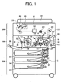
- Numeral number 100 denotes a copier apparatus body.
- a reading and writing apparatus 200 may be attached above the copier apparatus body.
- the copier apparatus body may be set on a table like sheet bank 300.
- the copier apparatus body 100 may include a drum shaped photo-conductive member (PC member) 10 as an image bearer.
- An upward charger 12, a developing apparatus 13, a transfer and transportation apparatus 14, a cleaning apparatus 15, and a charge removing apparatus 11 may be arranged one after another in this order in a clockwise direction "A" around the photo-conductive member 10.
- a sheet transportation path B may be formed in the apparatus body so as to transport a sheet (i.e., a transfer member), such as an OHP film, etc., from right to left in the drawing via a gap formed between the PC member 10 and a unit of transfer and transportation apparatus 14.
- a register roller 16 may be disposed upstream of the PC member 10 on the sheet transportation path B.
- a fixing apparatus 17 may be disposed downstream of the PC member 10 along the sheet transportation path B.
- the fixing apparatus 17 may include a fixing roller 18 installing a heater and a pressure applying roller 19 pressure contacting the fixing roller 18.
- An ejection roller 20 may be disposed in a left side of the fixing apparatus 17.
- the reading and writing apparatus 200 may include a laser writing apparatus 22 and a manuscript reading apparatus 23.
- the laser writing apparatus 22 may include a laser light source (not shown), a polygon mirror 24 for scanning use, a polygon motor 25, a scanning optical unit 26 such as an f ⁇ lens.
- the manuscript reading apparatus 23 may include a light source 28, a plurality of mirrors 29 and an image sensor 30 such as a CCD.
- an exposure glass 31 may be arranged upside thereof.
- a document cover 32 may be attached thereto being openable in order to cover the exposure glass 31.
- the sheet bank 300 may include a plurality of multistage type sheet cassettes 34.
- Each sheet cassette 34 may include a supplying roller 35 and a separation roller 36.
- a sheet feeding passage C may be formed from the right side of the multistage type sheet cassettes 34 to a sheet transportation path B extended in the image forming apparatus body 100.
- the sheet feeding passage C may include a certain number of transportation rollers 37.
- the image forming apparatus body 100 may include an openable and manually sheet feeding tray 38 for guiding a manually inserted sheet to the sheet transportation passage B on the right side surface thereof.
- a sheet ejection tray 39 may be attached to the left side surface so as to receive an image-recorded sheet ejected by an ejection roller 20.
- the document cover is open and a document is set onto the exposure glass 31. Then, a start switch (not shown) may be depressed.
- the document reading apparatus 23 may be driven and the light source 28 may be moved along the exposure glass 31.
- a light beam from the light source 28 may be reflected by the surface of the document.
- the reflected light may then be further reflected by a plurality of mirrors 29 and enter into an image sensor 30, thereby contents of the document may be read by the image sensor 30.
- a PC member driving motor (not shown) may rotate the PC member 10, and the charger 12 including a charge roller in this example may uniformly charge the surface of the PC member 10.
- the laser writing apparatus 22 may write with a laser light in accordance with the contents of the document read by the document reading apparatus 23, so that a latent image can be formed on the surface of the PC member 10.
- the developing apparatus 13 may visualize the latent image by affixing toner thereto.
- an appropriate supply roller 35 may be rotated, so that some sheets can be supplied from a corresponding sheet cassette 34 among the plurality of multistage type sheet cassettes 34.
- a following separation roller 36 may separate and guide sheets one by one to the sheet feeding passage C.
- the transportation roller 37 may transfer and guide the sheet to the sheet feeding passage B.
- the sheet may then collide and stop at the register roller 16.
- the register roller 16 may rotate and feed the sheet to a section below the PC member in synchronism with the rotation of the PC member 10.
- the supply roller 41 disposed on the manual sheet feeding section may be rotated and bring a sheet manually set on the opening manual sheet inserting tray 38 to the sheet transportation passage B. Then, the register roller 16 may similarly feed the sheet toward the section below the PC member 10 in synchronism with the rotation of the PC member 10.
- the transfer and transportation apparatus 14 including a transfer belt 40 may transfer a visible image onto the sheet fed to the below section.
- the cleaning apparatus 15 may remove and clean the toner remaining on the PC member 10 after image transfer.
- the charge removing apparatus 11 (see Fig. 2) may also remove a potential remaining on the PC member 10 in order to prepare for the next image formation started from charging of the charging apparatus 12.
- the sheet having received the toner transfer may then be fed to the fixing apparatus 17 by the transfer and transportation apparatus 17.
- the transferred image may then be fixed by the fixing apparatus 17 while the fixing and pressure applying rollers 18 and 19 apply heat and pressure thereto.
- the ejection roller 20 may eject and stack the sheet on the sheet ejection tray 39.
- the developing apparatus 13 may be formed from a developing tank 43 and a developing hopper 44.
- the developing tank 43 may include a developing roller 46, a paddle wheel 47, a stirring roller 48, a transfer screw 49, a separator 50, a doctor blade 51, and a toner density sensor 52, or the like.
- the developing tank 43 may accommodate two component type developer composed of at least carrier and toner.
- the developing roller 46 may include a cylindrical developing sleeve 65 made of nonmagnetic material, such as aluminum, brass, stainless, conductive plastic, etc. Also included may be a magnetic roller member 66 disposed in the developing sleeve 65 so as to form a magnetic field so that the developer can form a bristle on the outer surface of the developing sleeve 65.
- a rotation driving mechanism (not shown) may rotate the developing sleeve 65 counter clockwise.
- the developer hopper 44 may include a gear like toner replenishment member 54, a replenishment regulating plate 55, and an agitator 56 or the like.
- the developing hopper 44 may accommodate toner.
- the stirring roller 48 may rotate and frictionally discharge the two component developer in the developing casing of the developing apparatus 13.
- the paddle wheel 47 may then rotate and churn the developer up so that the developer adhere to the developing roller 46.
- the magnetic field lines may form a chain like bristle made of the carrier on the developing sleeve 65.
- the charged toner may simultaneously stick to the chain like bristle, thereby a magnetic brush may be achieved.
- the magnetic brush may be conveyed while the developing sleeve 65 rotates, and is regulated to have a prescribed thickness by the doctor blade 51. Specifically, the magnetic brush may adhere to the PC member 10 and develop the latent image on the PC drum 10 after the excessive amount is scraped.
- a toner rate (i.e., toner density) may accordingly decrease.
- the agitator 56 may rotate and stir the toner.
- the toner may be transported to the toner replenishment member 54, and is replenished to the developing tank 43 from the developer hopper 44 while the toner replenishment member 54 is rotated and the replenishment regulating plate 55 is swung.
- the toner density may be maintained within a prescribed range.
- a toner density sensor 52 may be attached to the developing casing 58 so as to detect the toner density of the developer.
- a value obtained by measuring (a density of) so called a "P" pattern (a measurement use toner image) formed on the PC member 10 with a photo sensor may be preset as a toner density target value.
- the toner adhering to the PC member 10 may electro-statically be transferred onto a sheet by the transfer and transportation apparatus 14 as described above. However, 10% of the toner may remain on the PC member 10 without being transferred. Such toner remaining on the PC member 10 may be scraped off by the cleaning blade 60 and brush roller 61 disposed in the cleaning apparatus 15 from the PC member 10.
- the cleaning apparatus 15 may form a recovery tank 62 in the cleaning casing 64 and include a cleaning blade 60, a brush roller 61, and a recovery screw 63.
- the cleaning blade 60 may be made of rubber, and contact the PC member 10 via its tip with a prescribed pressure and angle.
- the brush roller 61 may be formed from a metal bar on which brushes are hair implanted, and is rotated by a driving device (not shown) in a direction shown by an arrow in the drawing.
- the recovery screw 63 may be formed from a metal or plastic mold in a spiral shape.
- the brush roller 61 may initially scrape off the toner remaining on the PC member 10 after transfer. Subsequently, the toner surviving the initial scraping may be almost perfectly removed by the cleaning blade 60. The toner scraped off from the PC member 10 by the cleaning blade 60 and brush roller 61 may then enter into the recovery tank 62. Then, the toner may be transferred to one side of the cleaning apparatus 15 by a recovery screw 63.
- an air draining use-opening 70 may be formed on the developing casing 58 of the developing apparatus 13.
- a filter holding frame 71 may be arranged around the air draining use-opening 70.
- the other air draining use-opening 72 may be formed in the cleaning casing 64 of the cleaning apparatus 15.
- the other filter holding frame 73 may be also arranged around the air draining use-opening 72.
- a pair of air filters 74 and 75 may have substantially the same shape and material and are detachably attached to the respective filter holding frames 71 and 73.
- the air filters 74 and 75 may be made from paper, fabric, bonded fiber fabric, or multi porous synthetic plastic, or the like, and remove toner by either physically percolating or using an electrostatic absorption system, or the like.
- Such internal air pressure may be designed to be substantially the same in the respective developing and cleaning casings.
- scattering levels in those casings may be also designed to be substantially the same.
- substantially the same material and shape air filters 74 and 75 are employed as air draining use openings 70 and 72 in the developing and cleaning apparatuses 13 and 15, parts may be commonly used, and maintenance inventory may be decreased. As a result, maintenance cost may be decreased.
- respective air filters 74 and 75 can be either cleaned by a cleaner, or washed with water, or replaced with new ones, at substantially the same timing.
- a maintenance interval for at least one of parts of the developing and cleaning apparatuses 13 and 15 is designed to be substantially the same to that of the air filters 74 and 75, since maintenance timing for the other parts is substantially the same in addition to that of the respective air filters 74 and 75, maintenance labor and cost may be more decreased.
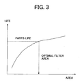
- Fig. 3 illustrates a relation between an area of an air filter 74 or 75 and a life. As understood therefrom, the larger the area of the air filter 74 or 75, the longer the life. Accordingly, as shown by a dotted line in the drawing, if an optimal area air filter 74 or 75 is used in accordance with the part life, maintenance intervals for these may be substantially the same.
- a monochrome copier in which a toner image formed on a PC member 10 is directly transferred to a sheet serving as a transfer member may be employed in the above-described example.
- the present invention is not limited thereto and can be applied to the other type of an image forming apparatus, such as a printer, a facsimile, etc., in a similar manner.
- a color image forming apparatus in which a toner image formed on an image bearer is temporary transferred onto a medium transfer member, and is transferred therefrom onto a sheet, may also similarly employ the present invention.
- Figs. 4 and 5 the above-described respective processing devices 11, 13, 14, 15 may be integrated together with the PC drum 140 in a casing 101 as a process cartridge so as to be integrally attached and discarded.
- the process cartridge can only include one of the processing devices 11, 13, 14, 15 and the PC drum 10.
- the process cartridge can also include the entire PC drum 10, charging apparatus 12, developing apparatus 13, and cleaning apparatus 15 in a body.
- Fig. 5 illustrates a recycle type image forming apparatus.
- a recovery screw 63 may be provided so as to transfer collected toner in the cleaning tank 62 toward the front side of the cleaning apparatus 15.
- a toner recycle pipe 103 may be provided so as to connect to the recovery screw 63 with its one end and to the developing device 13 with the other end.
- a transfer coil may be provided in the toner recycle pipe 103 so as to receive driving force from a driving device (not shown) and rotate so as to transfer the collected toner to the developing apparatus 13.
- the recycled toner may be blended with fresh toner in the developing apparatus and serve as developer used in the developing process.
- air may also be transferred in the developing device 13, the internal air pressure may further rise. However, the filter may lower the excessive internal pressure.
- substantially the same means to be at least in a range of ⁇ 50%, ⁇ 30%, ⁇ 10% or ⁇ 5%.
- the internal pressure of the developing apparatus and the cleaning apparatus is preferably within this range.
- the air filters are preferably substantially the same such that the filtering effectivity is within this range after a predetermined time of operation (of the toner scattering suppressing apparatus or the image forming apparatus).
- the toner scattering level corresponds in particular to the amount of toner scattered in particular during operation, in particular during one image formation and/or within a predetermined time.
- the constitution of developing apparatus and the cleaning apparatus in order to define the internal pressure is in particular such that the volume of the casing is adjusted to achieve the predetermined internal pressure.
- the rotation speed and surface of the rotating members which have an interference on the internal pressure may be adapted in order to achieve the desired internal pressure.
- the inner shape of the casing of the developing apparatus and/or the cleaning apparatus may be chosen such that the desired internal pressure is achieved.
- the toner scattering level may also be influenced by adjusting the volume inside the developing apparatus and/or cleaning apparatus.
- the rotation speed of the rotating members may be adjusted in order to achieve the desired amount of toners scattered (dispersed) inside the developing apparatus and the cleaning apparatus. In particular, it is desired to adjust that amount of toner to a predetermined level which is apt to flow towards the air filters. In other words, preferably that kind of amount of toner is adjusted which is apt to clog the air filters.
Landscapes
- Physics & Mathematics (AREA)
- General Physics & Mathematics (AREA)
- Dry Development In Electrophotography (AREA)
- Cleaning In Electrography (AREA)
- Control Or Security For Electrophotography (AREA)
Applications Claiming Priority (2)
| Application Number | Priority Date | Filing Date | Title |
|---|---|---|---|
| JP2001204546 | 2001-07-05 | ||
| JP2001204546 | 2001-07-05 |
Publications (3)
| Publication Number | Publication Date |
|---|---|
| EP1288731A2 true EP1288731A2 (fr) | 2003-03-05 |
| EP1288731A3 EP1288731A3 (fr) | 2003-03-12 |
| EP1288731B1 EP1288731B1 (fr) | 2012-04-11 |
Family
ID=19040995
Family Applications (1)
| Application Number | Title | Priority Date | Filing Date |
|---|---|---|---|
| EP02014902A Expired - Lifetime EP1288731B1 (fr) | 2001-07-05 | 2002-07-05 | Appareil pour supprimer la dispersion de toner et appareil de formation d'images |
Country Status (2)
| Country | Link |
|---|---|
| US (1) | US6985165B2 (fr) |
| EP (1) | EP1288731B1 (fr) |
Families Citing this family (5)
| Publication number | Priority date | Publication date | Assignee | Title |
|---|---|---|---|---|
| JP4451668B2 (ja) * | 2004-01-27 | 2010-04-14 | 株式会社リコー | 現像装置、プロセスカートリッジ及び画像形成装置 |
| US8032055B2 (en) * | 2007-08-08 | 2011-10-04 | Ricoh Company, Ltd. | Developing device, process cartridge including developing device, and image forming apparatus including process cartridge |
| JP5428690B2 (ja) * | 2009-09-15 | 2014-02-26 | 富士ゼロックス株式会社 | 画像形成装置 |
| JP2011112775A (ja) | 2009-11-25 | 2011-06-09 | Ricoh Co Ltd | 現像装置および画像形成装置およびプロセスカートリッジ |
| JP6618755B2 (ja) * | 2015-10-08 | 2019-12-11 | シャープ株式会社 | 画像形成装置 |
Family Cites Families (8)
| Publication number | Priority date | Publication date | Assignee | Title |
|---|---|---|---|---|
| JPS5699364A (en) * | 1980-01-11 | 1981-08-10 | Olympus Optical Co Ltd | Magnet roll developing device |
| JPH04260070A (ja) * | 1991-02-15 | 1992-09-16 | Canon Inc | 画像形成装置 |
| JP3483087B2 (ja) * | 1995-04-14 | 2004-01-06 | 株式会社リコー | 画像形成システム |
| JPH09185237A (ja) * | 1995-12-29 | 1997-07-15 | Ricoh Co Ltd | 現像装置 |
| US5950055A (en) * | 1997-04-18 | 1999-09-07 | Ricoh Company, Ltd. | Powder pump and image forming apparatus having the powder pump and method therefor |
| US6249305B1 (en) * | 1997-05-16 | 2001-06-19 | Konica Corporation | Color image forming apparatus |
| JP2001005365A (ja) * | 1999-06-21 | 2001-01-12 | Canon Inc | 画像形成装置 |
| CA2337087C (fr) * | 2000-03-08 | 2006-06-06 | Canon Kabushiki Kaisha | Vireur magnetique, processus de production connexe et methode, appareil et cartouche de production d'image faisant appel au vireur |
-
2002
- 2002-07-05 US US10/188,754 patent/US6985165B2/en not_active Expired - Lifetime
- 2002-07-05 EP EP02014902A patent/EP1288731B1/fr not_active Expired - Lifetime
Also Published As
| Publication number | Publication date |
|---|---|
| US20030016964A1 (en) | 2003-01-23 |
| EP1288731A3 (fr) | 2003-03-12 |
| US6985165B2 (en) | 2006-01-10 |
| EP1288731B1 (fr) | 2012-04-11 |
Similar Documents
| Publication | Publication Date | Title |
|---|---|---|
| EP1288731B1 (fr) | Appareil pour supprimer la dispersion de toner et appareil de formation d'images | |
| JPH10282854A (ja) | 画像形成方法及び画像形成装置 | |
| EP1031889A1 (fr) | Lame de chargement et de nettoyage combiné | |
| JPH09134104A (ja) | 画像形成装置 | |
| JP2007033468A (ja) | 画像形成装置 | |
| US11320771B2 (en) | Image forming apparatus provided with a developing device and a cleaning device for an image carrying member | |
| JP2003084634A (ja) | トナー飛散防止装置、プロセスカートリッジおよび画像形成装置 | |
| JP7452117B2 (ja) | 清掃装置、及び画像形成装置 | |
| JP2002311711A (ja) | トナー回収容器、トナー回収装置、および画像形成装置 | |
| JP2006030491A (ja) | 画像形成装置 | |
| JP2002229331A (ja) | トナー飛散防止装置、およびそれを備える画像形成装置 | |
| CN100492209C (zh) | 图像形成装置 | |
| JP2000321872A (ja) | 画像形成装置 | |
| JP3486086B2 (ja) | 画像形成装置 | |
| US11947303B1 (en) | Cleaner assembly with fabric seal for removing waste toner within an image forming device | |
| JP3645560B2 (ja) | クリーニングユニット | |
| JP5448767B2 (ja) | 画像形成装置 | |
| JP3582178B2 (ja) | 画像形成装置 | |
| JP3233466B2 (ja) | 画像形成装置 | |
| JP2000258979A (ja) | 電子写真装置 | |
| JP4312886B2 (ja) | 画像形成装置 | |
| JP2007271856A (ja) | トナ−飛散防止装置、プロセスカ−トリッジおよび画像形成装置 | |
| JP3537644B2 (ja) | 画像形成装置 | |
| JP5216750B2 (ja) | 画像形成装置 | |
| JP3489591B2 (ja) | トナークリーナ |
Legal Events
| Date | Code | Title | Description |
|---|---|---|---|
| PUAI | Public reference made under article 153(3) epc to a published international application that has entered the european phase |
Free format text: ORIGINAL CODE: 0009012 |
|
| PUAL | Search report despatched |
Free format text: ORIGINAL CODE: 0009013 |
|
| AK | Designated contracting states |
Kind code of ref document: A2 Designated state(s): AT BE BG CH CY CZ DE DK EE ES FI FR GB GR IE IT LI LU MC NL PT SE SK TR Designated state(s): AT BE BG CH CY CZ DE DK EE ES FI FR GB GR IE IT LI LU MC NL PT SE SK TR |
|
| AX | Request for extension of the european patent |
Extension state: AL LT LV MK RO SI |
|
| AK | Designated contracting states |
Designated state(s): AT BE BG CH CY CZ DE DK EE ES FI FR GB GR IE IT LI LU MC NL PT SE SK TR Kind code of ref document: A3 Designated state(s): AT BE BG CH CY CZ DE DK EE ES FI FR GB GR IE IT LI LU MC NL PT SE SK TR |
|
| AX | Request for extension of the european patent |
Extension state: AL LT LV MK RO SI |
|
| 17P | Request for examination filed |
Effective date: 20030423 |
|
| AKX | Designation fees paid |
Designated state(s): DE FR GB |
|
| 17Q | First examination report despatched |
Effective date: 20060626 |
|
| GRAP | Despatch of communication of intention to grant a patent |
Free format text: ORIGINAL CODE: EPIDOSNIGR1 |
|
| GRAS | Grant fee paid |
Free format text: ORIGINAL CODE: EPIDOSNIGR3 |
|
| GRAA | (expected) grant |
Free format text: ORIGINAL CODE: 0009210 |
|
| AK | Designated contracting states |
Kind code of ref document: B1 Designated state(s): DE FR GB |
|
| REG | Reference to a national code |
Ref country code: GB Ref legal event code: FG4D |
|
| REG | Reference to a national code |
Ref country code: DE Ref legal event code: R096 Ref document number: 60242596 Country of ref document: DE Effective date: 20120531 |
|
| PLBE | No opposition filed within time limit |
Free format text: ORIGINAL CODE: 0009261 |
|
| STAA | Information on the status of an ep patent application or granted ep patent |
Free format text: STATUS: NO OPPOSITION FILED WITHIN TIME LIMIT |
|
| 26N | No opposition filed |
Effective date: 20130114 |
|
| REG | Reference to a national code |
Ref country code: DE Ref legal event code: R097 Ref document number: 60242596 Country of ref document: DE Effective date: 20130114 |
|
| REG | Reference to a national code |
Ref country code: FR Ref legal event code: PLFP Year of fee payment: 15 |
|
| REG | Reference to a national code |
Ref country code: FR Ref legal event code: PLFP Year of fee payment: 16 |
|
| REG | Reference to a national code |
Ref country code: FR Ref legal event code: PLFP Year of fee payment: 17 |
|
| PGFP | Annual fee paid to national office [announced via postgrant information from national office to epo] |
Ref country code: FR Payment date: 20210727 Year of fee payment: 20 |
|
| PGFP | Annual fee paid to national office [announced via postgrant information from national office to epo] |
Ref country code: GB Payment date: 20210721 Year of fee payment: 20 Ref country code: DE Payment date: 20210721 Year of fee payment: 20 |
|
| REG | Reference to a national code |
Ref country code: DE Ref legal event code: R071 Ref document number: 60242596 Country of ref document: DE |
|
| REG | Reference to a national code |
Ref country code: GB Ref legal event code: PE20 Expiry date: 20220704 |
|
| PG25 | Lapsed in a contracting state [announced via postgrant information from national office to epo] |
Ref country code: GB Free format text: LAPSE BECAUSE OF EXPIRATION OF PROTECTION Effective date: 20220704 |