EP1288923B1 - Informationsaufzeichnungsvorrichtung und Informationsaufzeichnungsverfahren - Google Patents
Informationsaufzeichnungsvorrichtung und Informationsaufzeichnungsverfahren Download PDFInfo
- Publication number
- EP1288923B1 EP1288923B1 EP02256026A EP02256026A EP1288923B1 EP 1288923 B1 EP1288923 B1 EP 1288923B1 EP 02256026 A EP02256026 A EP 02256026A EP 02256026 A EP02256026 A EP 02256026A EP 1288923 B1 EP1288923 B1 EP 1288923B1
- Authority
- EP
- European Patent Office
- Prior art keywords
- period
- level
- space
- recording
- laser
- Prior art date
- Legal status (The legal status is an assumption and is not a legal conclusion. Google has not performed a legal analysis and makes no representation as to the accuracy of the status listed.)
- Expired - Lifetime
Links
- 238000000034 method Methods 0.000 title claims description 19
- 230000001678 irradiating effect Effects 0.000 claims description 5
- 230000001052 transient effect Effects 0.000 abstract description 27
- 238000009825 accumulation Methods 0.000 abstract description 5
- 230000003287 optical effect Effects 0.000 description 49
- 230000015572 biosynthetic process Effects 0.000 description 11
- PSVRFUPOQYJOOZ-QNPWAGBNSA-O 2-[hydroxy-[(2r)-2-[(5z,8z,11z,14z)-icosa-5,8,11,14-tetraenoyl]oxy-3-octadecanoyloxypropoxy]phosphoryl]oxyethyl-trimethylazanium Chemical compound CCCCCCCCCCCCCCCCCC(=O)OC[C@H](COP(O)(=O)OCC[N+](C)(C)C)OC(=O)CCC\C=C/C\C=C/C\C=C/C\C=C/CCCCC PSVRFUPOQYJOOZ-QNPWAGBNSA-O 0.000 description 4
- 230000000052 comparative effect Effects 0.000 description 4
- 238000010586 diagram Methods 0.000 description 2
- 230000000694 effects Effects 0.000 description 2
- 230000001105 regulatory effect Effects 0.000 description 1
Images




Classifications
-
- G—PHYSICS
- G11—INFORMATION STORAGE
- G11B—INFORMATION STORAGE BASED ON RELATIVE MOVEMENT BETWEEN RECORD CARRIER AND TRANSDUCER
- G11B7/00—Recording or reproducing by optical means, e.g. recording using a thermal beam of optical radiation by modifying optical properties or the physical structure, reproducing using an optical beam at lower power by sensing optical properties; Record carriers therefor
- G11B7/004—Recording, reproducing or erasing methods; Read, write or erase circuits therefor
- G11B7/006—Overwriting
- G11B7/0062—Overwriting strategies, e.g. recording pulse sequences with erasing level used for phase-change media
-
- G—PHYSICS
- G11—INFORMATION STORAGE
- G11B—INFORMATION STORAGE BASED ON RELATIVE MOVEMENT BETWEEN RECORD CARRIER AND TRANSDUCER
- G11B7/00—Recording or reproducing by optical means, e.g. recording using a thermal beam of optical radiation by modifying optical properties or the physical structure, reproducing using an optical beam at lower power by sensing optical properties; Record carriers therefor
- G11B7/004—Recording, reproducing or erasing methods; Read, write or erase circuits therefor
- G11B7/0045—Recording
- G11B7/00456—Recording strategies, e.g. pulse sequences
Definitions
- the present invention belongs to a technology to record the information onto the optical disk by using the laser light beam.
- the laser light is irradiated onto the recording surface of the disk and the information is recorded in the writable or re-writable optical disk such as DVD-R (DVD-Recordable) or DVD-RW (DVD-Re-recordable).
- DVD-R DVD-Recordable
- DVD-RW DVD-Re-recordable
- the recording pulse having the time width corresponding to the information to be recorded the laser light is modulated, and the laser pulse having the length corresponding to the signal to be recorded is generated, and by irradiating this onto the optical disk, the recording mark having the length corresponding to the information to be recorded, can be formed on the optical disk.
- one recording mark is not formed by the one laser pulse, and a method by which the recording mark is formed by the pulse train including a plurality of short pulses, is used.
- Such a method is also called write strategy, and as compared to a method by which a single recording pulse is irradiated, because the heat accumulation on the recording surface of the optical disk is reduced, the temperature distribution on the recording surface on which the recording mark is formed can be uniformed. As the result, it is prevented that the recording mark becomes the tear drop shape, and the preferably shaped recording mark can be formed.
- the above recording pulse train is structured by a plurality of pulses whose amplitude is varied between a predetermined read power level and write power level. That is, according to the recording signal, in the area on the recording surface of the optical disk (hereinafter, called also " space portion") in which the recording mark is not formed, the laser light is irradiated onto the recording surface by the read power, and in the area on the recording surface of the optical disk (hereinafter, called also "mark portion”) in which the recording mark is to be formed, the laser light is irradiated onto the recording surface by the power corresponding to the recording pulse train whose amplitude is varied between the read power and the write power, thereby, the recording mark is formed on the recording surface.
- the laser irradiation level (bias level) after the irradiation of the recording pulse is increased.
- the recording pulse whose amplitude is varied between the read power and write power, and after the completion of the recording pulse, theoretically, the laser irradiation level instantaneously returns to the readpower.
- the laser irradiation level instantaneously changes from the write power to the read power, the transient response of the recording pulse is generated, and the laser irradiation level does not instantaneously return to the read power, but rather than it, the laser irradiation level is increased for a constant period.
- the recording pulse is completed, although it is a short time, a period in which the laser irradiation level is higher than the read power level, is generated.
- the space period to the next recording mark is short, because there is the residual heat by the above transient response at the time of formation of the next recording mark, there is a case where the next recording mark can not be correctly formed.
- this influence is specifically prominent when the recording speed is increased, that is, when the high speed recording is conducted onto the optical disk.
- the recording speed is increased to 2 times or 3 times of the normal one, because the time interval of the recording pulse train becomes short, the next recording pulse train comes under the condition that the residual heat is remained, and the possibility that the residual heat due to the above transient response influences the next recording mark as the heat interference is increased.
- the recording speed is increased, in order to form the recording mark correctly, it is necessary that the recording power is increased corresponding to the increased amount of the recording speed. Accordingly, the increase of the laser irradiation level becomes large, and the bad influence is increased.
- EP0991058A discloses a recording method for re-recordable optical media in which the output level of the laser is reduced from a normal, erase (or "bias") level following a mark period so as to avoid the formation of teardrop shaped marks and associated jitter.
- JP 2000285453 discloses a recording method for optical media recording in which the laser beam is outputted as a pulse beam comprising a train of pulses changing between on and off power levels of predetermined output values
- the present invention is attained, and the object of the present invention is to provide an information recording apparatus and the method by which, even at the time of the high speed recording, the influence of the transient response of the recording pulse train is eliminated and the correct recording mark can be formed.
- the invention consists in an information recording apparatus in which a laser light is irradiated onto a recording medium in which recording can be conducted only once and recording marks and spaces corresponding to a recording signal are formed, said information recording apparatus comprising:
- the laser pulse corresponding to the recording signal is irradiated onto the recording medium.
- the recording signal has the mark period to form the recording mark and the space period in which the recording mark is not formed.
- the output level of the laser pulse changes between the normal level and the writing level, thereby, the recording mark is formed on the recording medium.
- the output level of the laser pulse is changed to the low level lower than the normal level.
- the low level lower than the reading level is a zero level.
- the space controller changes the output level of the laser pulse to the low level lower than the reading level only in space periods in which the time width is short.
- the output level of the laser pulse is reduced only in the space period in which the time width is short.
- the time width of the space period is short, while the heat on the recording medium by the laser pulse irradiated in the mark period preceding to that, is not sufficiently reduced, the next mark period comes and the probability in which the bad influence such as the heat interference is given to the next recording mark formation, is large. Accordingly, even when the output level of the laser pulse is reduced only in the space period in which the time width is short, good effect can be obtained.
- the space periods in which the time width is short are the space periods of 3T or 4T.
- the space controller changes the output level of the laser pulse to the low level lower than the reading level in all space periods.
- the space controller changes the output level of the laser pulse to the low level over a predetermined first period, and in a space period in which the time width is short, the output level of the laser pulse is changed to the low level over a second period which is longer than the first period.
- a space period in which the time width is short is a space period of 3T or 4T
- a space period in which the time width is long is a space period of 5T or more.
- a level adjuster which automatically adjusts the output level of the laser pulse over a level adjustment period in the predetermined space period, and the space controller changes the output level of the laser pulse to the low level lower than the reading level only in a space period in which the output level is not automatically adjusted.
- the output level of the laser pulse is lowered only in the space period in which the output level of the laser pulse is not automatically adjusted.
- a level adjuster which automatically adjusts the output level of the laser pulse over a level adjustment period in the predetermined space period, and the space controller changes the output level of the laser pulse to the low level lower than the reading level in all space periods, in the period other than level adjustment period.
- the output level of the laser pulse can be lowered.
- a level adjuster which automatically adjusts the output level of the laser pulse over a level adjustment period in the predetermined space period
- the space controller changes the output level of the laser pulse to the low level over a predetermined first period which does not overlap with the level adjustment period, in the space period in which the automatic adjustment of the output level is conducted, and in the space period in which automatic adjustment of the output level is not conducted, over a second period longer than the first period, the output level of the laser pulse is changed to the low level.
- the output level of the laser pulse is lowered over a long period, and in the space period in which the automatic adjustment of the laser pulse is conducted, the output level of the laser pulse is lowered in the range which does not influence the automatic adjustment.
- the space controller changes the output level of the laser pulse to the low level lower than the reading level from the start of a space period.
- the invention consists in an information recording method in which laser light is irradiated onto a recording medium in which recording can be conducted only once and recording marks and spaces corresponding to a recording signal are formed, said information recording method comprising the steps of:
- the laser pulse corresponding to the recording signal is irradiated onto the recording medium.
- the recording signal has the mark period to form the recording mark, and the space period in which the formation of the recording mark is not conducted.
- the output level of the laser pulse changes between the normal level and the writing level, thereby, the recording mark is formed on the recording medium.
- the output level of the laser pulse is changed to the low level lower than the normal level.
- the information recording reproducing apparatus 1 records the information in an optical disk D, and reproduces the information from the optical disk D.
- optical disk D various optical disks such as, for example, CD-R (Compact Disc-Recordable), DVD-R in which the recording can be conducted only once, or CD-RW (Compact Disc-Rewritable), DVD-RW in which, over a plurality of times, the erasing and recording can be conducted, can be used.
- the information recording reproducing apparatus 1 is provided with: an optical pick-up 2 by which the recording beam and reproducing beam are irradiated onto the optical disk D; a spindle motor 3 by which the rotation of the optical disk D is controlled; a recording control section 10 by which the recording of the information onto the optical D disk is controlled; a reproducing control section 20 by which the reproduction of the information which is already recorded in the optical disk is controlled; and a servo control section 30 by which each kind of servo control including a spindle servo to control the rotation of the spindle motor 3, and a focus servo which is a relative position control of the optical pick-up 2 to the optical disk D, and a tracking servo, is conducted.
- the recording control section 10 receives the recording signal, and generates a drive signal S D to drive the laser diode inside the optical pick-up 2 by the processing which will be described later, and supplies it to the optical pick-up 2.
- the reproducing control section 20 receives the reading RF signal Srf outputted from the optical pick-up 2, and a predetermined demodulation processing and decoding processing are conducted on that, and the reproduction signal is generated and outputted.
- the servo control section 30 receives the reading RF signal Srf from the optical pick-up 2, and according to that, a servo signal S1 such as the tracking error signal, and focus signal is supplied to the optical pick-up 2, and the spindle servo signal S2 is supplied to the spindle motor 3. Thereby, each kind of servo processing such as the tracking servo, focus servo, or spindle servo, is conducted.
- the present invention mainly relates to the recording method in the recording control section 10, and for the reproducing control and servo control, because the already known various methods can be applied, for these methods, the detailed description is not conducted.
- Fig. 1 the information recording reproducing apparatus as one embodiment of the present invention is shown, however, the present invention can also be applied to the recording-only information recording apparatus.
- the optical pick-up 2 is provided with: a laser diode LD which generates the recording beam to record the information to the optical disk D and the reproducing beam to reproduce the information from the optical disk D; and a front monitor diode (FMD) 16 which receives the laser light emitted from the laser diode LD and outputs the laser power level signal LDout corresponding to the laser light.
- a laser diode LD which generates the recording beam to record the information to the optical disk D and the reproducing beam to reproduce the information from the optical disk D
- FMD front monitor diode
- the optical pick-up 2 is provided with, other than that, already known components such as an optical detector to receive the reflection beam by the optical disk D of the reproducing beam and generate the reading RF signal Srf, and the optical system to guide the recording beam and reproduction beam, and reflection beam to an adequate direction, however, those illustrations and detailed description will be omitted.
- the recording control section 10 is provided with a laser diode (LD) driver 12, APC (Automatic Power Control) circuit 13, sample hold (S/H) circuit 14, and controller 15.
- LD laser diode
- APC Automatic Power Control
- S/H sample hold
- the LD driver 12 supplies the current corresponding to the recording signal to the laser diode LD, and conducts the recording of the information onto the optical disk D.
- the front monitor diode 16 is arranged in the vicinity of the laser diode LD in the optical pick-up 2, receives the laser light emitted from the laser diode LD, and outputs the laser power level signal LDout showing the level.
- the sample hold circuit 14 samples the level of the laser power level signal LDout at the timing regulated by the sample hold signal APC-S/H, and holds it.
- the APC circuit 13 power-controls the LD driver 12 so that the read power level of the laser light emitted from the laser diode LD becomes constant, according to the output signal of the sample hold circuit 14.
- the controller 15 mainly conducts the recording operation and APC operation. Initially, the recording operation will be described. In the recording operation, the controller 15 generates the switching signal SW R and SW W of the switch to control the current amount supplied to the laser diode LD, and supplies it to the LD driver 12.
- the LD driver 12 is provided with the current source 17R for the read level, the current source 17W for the write level, and switches 18R and 18w.
- the current source 17R for the read level is the current source which flows the drive current I R to make the laser diode LD emit the laser light by the read power, and the drive current I R is supplied to the laser diode LD through the switch 18R. Accordingly, when the switch 18R is turned on, the drive current I R of the read power is supplied to the laser diode LD, and when the switch 18R is turned off, the supply of the drive current I R is stopped. The magnitude of the current from the current source 17R is changed by the control signal S APC .
- the current source 17W for the write level is the current source which flows the drive current I w to make the laser diode LD emit the laser light by the write power, and the drive current I w is supplied to the laser diode LD through the switch 18W. Accordingly, when the switch 18W is turned on, the drive current I w of the write power is supplied to the laser diode LD, and when the switch 18W is turned off, the supply of the drive current I w is stopped.
- Fig. 4 the relationship between the drive current supplied to the laser diode LD, and the output power of the laser light which is emitted from the laser diode LD, is shown.
- the drive current I R when the drive current I R is supplied to the laser diode LD, the laser light is emitted by the read power P R .
- the drive current I W when the drive current I W is further added, the laser light is emitted by the write power P W .
- the drive current I R is always supplied, and the laser light is emitted by the read power P R , and further, according to the recording pulse, by adding the drive current I w , the write power P W is applied, and the information is recorded onto the optical disk.
- the present invention it is characterized that: after the last pulse of the recording pulse train of the write power is applied, both of the switches 18R and 18W are temporarily simultaneously turned off, and the drive current is made zero, thereby, the influence of the transient response is removed.
- the APC operation is an operation by which the drive current level supplied from the LD driver 12 to the laser diode LD is adjusted so that the level of the read power of the laser light outputted from the laser diode LD becomes constant.
- the drive signal S D from the LD driver 12 is adjusted so that the level of the read power becomes constant.
- the controller 15 generates the recording pulse corresponding to the recording signal as described above, and by the recording pulse, the LD driver 12 is driven and the laser light is emitted from the laser diode LD.
- the front monitor diode 16 is arranged in the vicinity of the laser diode LD in the optical pick-up 2, receives the laser light emitted from the laser diode LD, and the laser power level signal LDout showing the level is generated, and supplied to the sample hold circuit 14.
- the sample hold circuit 14 samples the laser power level signal LDout supplied from the front monitor diode 16, at the timing given by the sample hold signal APC-S/H inputted from the controller 15, and holds its level for a predetermined period.
- the sample hold signal APC-S/H outputted from the controller 15 is a pulse showing the period in which the APC is conducted, and specifically, a pulse signal showing a predetermined period (the period in which the APC is conducted, and hereinafter, called also "APC period") in the comparatively long space period in the recording signal (5T - 11T).
- the sample hold circuit 14 holds the level of the laser power level signal LDout in the APC period in the space period of the recording signal and supplies it to the APC circuit 13.
- the APC circuit 13 supplies the control signal S APC to the LD driver 12 so that the level of the laser power level signal LDout becomes constant in the APC period.
- the control signal S APC is inputted into the current source 17R for the read level in the LD driver 12 as shown in Fig. 3 . Thereby, corresponding to the control signal S APC , the current I R flowing from the current source 17R for the read level is changed. That is, the APC is conducted so that the read power level obtained from the laser diode LD becomes constant.
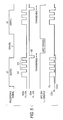
- Fig. 5 is a timing chart showing the waveform of each portion of the recording control section 10.
- the first embodiment is an example in which the recording control of the present invention is applied to the recording of DVD-R.
- the recording signal is a 8-16 modulation signal, and corresponds to the mark to be formed on the recording surface of the optical disk, and has the mark period and space period.
- the mark period and space period of 3T - 11T, 14T are included.
- the mark period of the length 6T, space period of 5T, and mark period of 5T are shown.
- the switching signal SW R is a signal to switch the switch 18R connected to the current source 17R for the read power shown in Fig. 3 , and as a principle, it is turned on in both of the mark period and space period.
- the switching signal SW W to switch the switch 18W connected to the current source 17W for the write power is switched according to the recording pulse train.
- the recording pulse train is switched corresponding to a top pulse 120 whose time width is long, and the multi-pulse following that (called also "pulse train") 121.
- both of the switches 18R and 18W are turned off, and the current flowing the laser diode LD is made zero.
- the period in which the laser power level is higher than the read power level is generated, however, as described above, in a predetermined period after the last pulse of the power train is completed, the read power is also turned off (hereinafter, the period is called "laser off period"), by making the current of the laser diode LD zero, the increase of the laser power level generated due to the transient response can be absorbed.
- the waveform of the laser power level signal Lout shown in Fig. 5 shows this situation. That is, in the mark period of the first 6T, initially, the read power P R is continuously applied, and the top pulse 120 having the amplitude of the write power P W and the pulse train 121 composed of 3 pulses are applied. Thereby, the recording mark whose length is 6T is formed on the recording surface of the optical disk.
- the laser power level signal LDout is lowered to the zero level LDoff. Then, when the laser off period 122 is completed, the laser power level signal LDout is increased to the read power level P R .
- the laser off period 122 is provided (however, because of 5T mark period, the pulse train 121 is composed of 2 pulses).
- the time width of the laser off period can be made changeable, and for example, it can be set to the arbitrary length between 1T - 2T.
- the time width of the laser off period there is a limitation in the relationship with the APC. As described above, for example, in the longer space period than 5T, the APC period is set, and the laser power level signal LDout is sample-held by the sample hold circuit 14, and because the APC is conducted so that the level is maintained, it is necessary that, in the APC period, the laser power level signal LDout is made to the read power level, and when the laser is turned off during the period, the hindrance occurs in the APC.
- the laser off period 122 can not overlap with the APC period (that is, the period in which the sample hold signal APC-S/H is in the low level).
- the APC period is set in such a manner that the period of before or after 1 - 2T in the space period of 5T - 11T is excepted as a margin, and it is set in the remained period. Accordingly, in the margin of 1 - 2T in the top of the space period, even when the laser is turned off, the hindrance does not occur in the APC. Therefore, in the space period in which the APC is conducted, it is preferable that, in the laser off period, after the mark period is completed, it is set before the start of the APC period. Actually, as described above, it is preferable that, in the margin of 1T - 2T provided in the top of the space period, the laser off period is set.
- Fig. 6 an actual example of waveform of the laser light is shown.
- Fig. 6A is a waveform of the laser power level signal LDout when the laser off period is not provided, which is prepared for the comparison
- Fig. 6B is the waveform of the laser power level signal LDout of the method (laser off period is provided) of the present application.
- the transient response is generated after the last pulse of the pulse train, and the laser power level is increased (refer to a portion of code 130).
- the laser power level is increased (refer to a portion of code 130).
- the laser power level signal Ldout temporarily drops to the zero level after the last pulse of the pulse train (refer to a portion of code 131). Accordingly, the residual heat on the recording surface of the optical disk is small, and the bad influence due to the heat interference can be prevented from being exerted onto the mark formation in the succeeding mark period.
- Fig. 7 shows, when the laser off period is provided, and not provided, the reading RF signal waveform of the recording mark empirically formed on the optical disk.
- Fig. 7A is a case where the laser off period is provided, and the envelope waveform of the reading RF signal of 3T mark, 4T mark, 5T mark, and 6T mark has a clear contour.
- Figs. 7B and 7C are envelope waveforms when the laser off period is not provided, and the heat interference due to the transient response of the pulse affects the succeeding mark formation.
- the contour of each envelope waveform is blurred and becomes bold, and in the case of Fig. 7C , further, it is seen as if each envelope wavelength is branched to two. Such the phenomenon is caused by that the recording mark is inadequately deformed due to the heat interference.
- the influence of the heat interference due to the transient response of the recording pulse is excluded and the correct recording mark can be formed.
- the laser off period is provided in the all space periods after the mark period, however, in the second embodiment, the laser off period is provided in only the short period (for example, the space period of 3T or 4T), and the laser off period is not provided in the long space period (for example, the space period more than 5T).
- the second embodiment is also an example in which the recording control of the present invention is applied to the recording of the DVD-R.
- the laser off period is provided for the purpose to remove the influence caused by that the laser power level is increased due to the transient response after the completion of the recording pulse as described above, however, when the space period following the mark period is long, because there is the afford of time to the next mark period, the transient response is hardly comparatively affected on the next mark period. In contrast to this, when the space period following the mark period is short, because the time to the next mark period is short, the probability that the residual heat of the level increased amount due to the transient response exerts a bad influence on the recording mark formation in the next mark period, is increased.
- the laser off period can be set longer than in the case of the first embodiment.
- the APC period to sample-hold the laser power level signal LDout for the APC is set. Therefore, it is necessary that the laser off period is not overlapped with the APC period, and the time width of the laser off period is practically limited to the length of about 1T - 2T.
- the laser off period is set only in the short space period (space period of 3T or 4T), and because the APC period is not set in the short space period, the laser off period can be set long.
- FIG. 8 shows the waveform of each portion of the recording control section 10 in the second embodiment, and the space period of 3T exists after the mark period of 6T, and further, the mark period of 5T follows.
- the space period of 3T because the APC period is not set, the sample hold signal APC-S/H remains in the high level, and the sample-hold of the laser power level signal LDout is not conducted. Accordingly, in the space period of 3T after the completion of the mark period of 6T, the laser off period 122 is set sufficiently long. Thereby, the residual heat on the information recording surface of the optical disk is reduced, and the influence of the transient response of the recording pulse can be effectively prevented from being exerted on the next mark period.
- the second embodiment is a method by which the laser off period is set only in the space period in which the APC is not conducted.
- the first embodiment and the second embodiment can be combined with each other. That is, as the first embodiment, the laser off period is provided in all mark periods, and as the second embodiment, in the short space period, the laser off period can be set long. Thereby, in the case of the short space, because the laser off period becomes long, the heat interference can be effectively prevented.
- FIG. 9 the waveform view of each portion of the recording control section 10 in the recording onto the DVD-RW is shown.
- the recording mark is formed by basically the same method as the DVD-R, however, because the erasing operation is conducted before the recording operation, as shown in the laser power level signal LDout in Fig. 9 normally, the laser power from the laser diode LD is on the erasing level P E . Accordingly, the APC is also conducted when the erasing level P E is sample-held in the APC period set in the long space period.
- the recording pulse train is structured by the top pulse 120 and the pulse train 121. Then, after the completion of the pulse train 121, the laser off period 122 is provided, and the laser power level is temporarily dropped to the zero level LDoff. After that, the laser power level returns to the erasing level P E which is steady state.
- the time width of the laser off period is limited to the range by which the erasing operation is not affected. That is, in the laser off period, because the laser power level does not come to the erasing level, the erasing of the information already recorded on the DVD-RW can not be conducted. Accordingly, when the laser off period is made too long, already recorded information can not be erased, and there is a disadvantage that un-erased portion of the information is generated. Accordingly, the time width of the laser off period is limited to the comparatively short period in which it does not affect the erasing of the information.
- the period in which the laser power-is dropped to the read level (it is called "cool pulse period”. Refer to the broken line 140 in Fig. 9 ) is provided. Accordingly, as one preferred method, when the laser off period is provided in the cool pulse period, the problem such as un-erased portion is not generated.
- the current value given to the laser diode LD is made zero so that the laser power level perfectly becomes zero.
- the laser power level is not perfectly made zero, when it is set to the low level lower than the read power level, because the residual heat onto the disk is reduced by the amount, the effect by which the influence of the heat interference is reduced, can be obtained.
- the laser off period is started after the last pulse in the mark period is completed, however, theoretically, when it is before the next mark period comes, in any portion in the space period, when the laser off period is provided, the heat interference with the next recording mark formation canbe reduced.
- the laser off period may not always start from just after the mark period completion.
- the laser off period in which the laser power is temporarily dropped to near the zero level is provided, the increase of the laser power level (bias level) due to the transient response of the recording pulse is softened, and the bad influence onto the next recording mark formation due to the heat interference can be prevented.
- This is effective in the point that the recording mark of the preferable shape can be formed particularly even in the case where the recording speed is heightened.
Landscapes
- Optical Recording Or Reproduction (AREA)
- Optical Head (AREA)
Claims (12)
- Informationsaufzeichnungsvorrichtung, in der ein Laserstrahl auf ein Aufzeichnungsmedium gestrahlt wird, in dem ein Aufzeichnen nur einmal ausgeführt werden kann und Aufzeichnungsmarken und Zwischenräume entsprechend einem Aufzeichnungssignal ausgebildet werden,
wobei die Informationsaufzeichnungsvorrichtung enthält:eine Lichtquelle zur Abgabe des Laserlichts; undeine Steuereinheit, die das Einstrahlen eines Laserimpulses auf das Aufzeichnungsmedium steuert, wenn die Lichtquelle entsprechend dem Aufzeichnungssignal betrieben wird, dadurch gekennzeichnet, dassdie Steuereinheit enthält:eine Marken-Steuereinheit, durch die während einer Markenperiode des Aufzeichnungssignals ein Ausgangspegel des Laserimpulses entsprechend dem Aufzeichnungssignal zwischen einem Lesepegel und einem Schreibpegel, der höher als der Lesepegel ist, geändert wird; undeine Zwischenraum-Steuereinheit, durch die während mehrerer Zwischenraumperioden im Aufzeichnungssignal der Ausgangspegel des Leserimpulses für eine vorbestimmte Zeitdauer auf einen niedrigen Pegel geändert wird, der niedriger als der Lesepegel ist. - Informationsaufzeichnungsvorrichtung nach Anspruch 1, bei der
der niedrige Pegel, der niedriger als der Lesepegel ist, ein Nullpegel ist. - lnformationsaufzeichnungsvorrichtung nach Anspruch 1, bei der
die Zwischenraum-Steuereinheit den Ausgangspegel des Laserimpulses auf den niedrigen Pegel, der niedriger als der Lesepegel ist, nur in Zwischenraumperioden ändert, in denen die Zeitdauer kurz ist. - Informationsaufzeichnungsvorrichtung nach Anspruch 3, bei der
die Zwischenraumperioden, in denen die Zeitdauer kurz ist, Zwischenraumperioden von 3T oder 4T sind. - Informationsaufzeichnungsvorrichtung nach Anspruch 1, bei der
die Zwischenraum-Steuereinheit den Ausgangspegel des Laserimpulses auf den niedrigen Pegel, der niedriger als der Lesepegel ist, in allen Zwischenraumperioden ändert. - Informationsaufzeichnungsvorrichtung nach Anspruch 1, bei der
in einer Zwischenraumperiode, in der die Zeitdauer lang ist, die Zwischenraum-Steuereinheit den Ausgangspegel des Laserimpulses auf den niedrigen Pegel für eine vorbestimmte erste Zeitdauer ändert, und
in einer Zwischenraumperiode, in der die Zeitdauer kurz ist, die Zwischenraum-Steuereinheit den Ausgangspegel des Laserimpulses auf den niedrigen Pegel für eine zweite Zeitdauer ändert, die länger als die erste Zeitdauer ist. - Informationsaufzeichnungsvorrichtung nach Anspruch 6, bei der
die Zwischenraumperiode, in der die Zeitdauer kurz ist, eine Zwischenraumperiode von 3T oder 4T ist und
die Zwischenraumperiode, in der die Zeitdauer lang ist, eine Zwischenraumperiode von 5T oder mehr ist. - Informationsaufzeichnungsvorrichtung nach Anspruch 1, weiterhin enthaltend:einen Pegeleinsteller, der automatisch den Ausgangspegel des Laserimpulses während einer Pegeleinstellperiode in der vorbestimmten Zwischenraumperiode einstellt, wobeidie Zwischenraum-Steuereinheit den Ausgangspegel des Laserimpulses auf den niedrigen Pegel, der niedriger als der Lesepegel ist, nur in einer Zwischenraumperiode einstellt, in der eine automatische Einstellung des Ausgangspegels nicht ausgeführt wird.
- Informationsaufzeichnungsvorrichtung nach Anspruch 1, weiterhin enthaltend:einen Pegeleinsteller, der automatisch den Ausgangspegel des Laserimpulses während einer Pegeleinstellperiode in der vorbestimmten Zwischenraumperiode einstellt, wobeidie Zwischenraum-Steuereinheit des Ausgangspegel des Laserimpulses auf den niedrigen Pegel, der niedriger als der Lesepegel ist, in der außerhalb der Pegeleinstellperiode liegenden Zeit in allen Zwischenraumperioden einstellt.
- Informationsaufzeichnungsvorrichtung nach Anspruch 1, weiterhin enthaltend:einen Pegeleinsteller, der automatisch den Ausgangspegel des Laserimpulses während einer Pegeleinstellperiode in der vorbestimmten Zwischenraumperiode einstellt, wobeiin einer Zwischenraumperiode, in der eine automatische Einstellung des Ausgangspegels ausgeführt wird, die Zwischenraum-Steuereinheit den Ausgangspegel des Laserimpulses auf den niedrigen Pegel für eine vorbestimmte erste Zeitdauer einstellt, die nicht mit der Pegel-einstellperiode überlappt, undin einer Zwischenraumperiode, in der eine automatische Einstellung des Ausgangspegels nicht ausgeführt wird, die Zwischenraum-Steuereinheit den Ausgangspegel des Laserimpulses für eine zweite Zeitdauer, die länger als die erste Zeitdauer ist, auf den niedrigen Pegel ändert.
- Informationsaufzeichnungsvorrichtung nach Anspruch 1, bei der
die Zwischenraum-Steuereinheit den Ausgangspegel des Laserimpulses auf den niedrigen Pegel, der niedriger als der Lesepegel ist, vom Beginn der Zwischenraumperiode an ändert. - Informationsaufzeichnungsverfahren, in dem Laserlicht auf ein Aufzeichnungsmedium gestrahlt wird, in den eine Aufzeichnung nur einmal vorgenommen werden kann und Aufzeichnungsmarken und Zwischenräume entsprechen dem Aufzeichnungssignal ausgebildet werden wobei das Informationsaufzeichnungsverfahren die folgenden Schritte umfasst:Abgeben eines Laserlichts; undEinstrahlen eines Laserimpulses in das Aufzeichnungsmedium durch Betreiben einer Lichtquelle entsprechend dem Aufzeichnungssignal, wobei
der Schritt der Einstrahlung des Laserimpulses die Schritte enthält:während einer Marken-Periode des Aufzeichnungssignals das Ändern des Ausgangspegels des Laserimpulses zwischen einem Lesepegel und einem Schreibpegel, der höher als der Lesepegel ist, entsprechend dem Aufzeichnungssignal; undwährend mehrerer Zwischenraumperioden des Aufzeichnungssignals das Ändern des Ausgangspegels des Laserimpulses für eine vorbestimmte Zeitdauer auf einen niedrigen Pegel, der niedriger als der Lesepegel ist.
Applications Claiming Priority (2)
| Application Number | Priority Date | Filing Date | Title |
|---|---|---|---|
| JP2001266460A JP4405115B2 (ja) | 2001-09-03 | 2001-09-03 | 情報記録装置および情報記録方法 |
| JP2001266460 | 2001-09-03 |
Publications (3)
| Publication Number | Publication Date |
|---|---|
| EP1288923A2 EP1288923A2 (de) | 2003-03-05 |
| EP1288923A3 EP1288923A3 (de) | 2004-12-22 |
| EP1288923B1 true EP1288923B1 (de) | 2008-07-16 |
Family
ID=19092745
Family Applications (1)
| Application Number | Title | Priority Date | Filing Date |
|---|---|---|---|
| EP02256026A Expired - Lifetime EP1288923B1 (de) | 2001-09-03 | 2002-08-30 | Informationsaufzeichnungsvorrichtung und Informationsaufzeichnungsverfahren |
Country Status (5)
| Country | Link |
|---|---|
| US (2) | US20030048724A1 (de) |
| EP (1) | EP1288923B1 (de) |
| JP (1) | JP4405115B2 (de) |
| AT (1) | ATE401646T1 (de) |
| DE (1) | DE60227621D1 (de) |
Families Citing this family (7)
| Publication number | Priority date | Publication date | Assignee | Title |
|---|---|---|---|---|
| EP1484191A4 (de) * | 2002-02-15 | 2005-03-02 | Sony Corp | Wiederbeschreibbares optisches datenaufzeichnungsmedium und aufzeichnungs-/reproduzierverfahren, aufzeichnungs-/reproduziervorrichtung |
| AU2003238901A1 (en) * | 2002-06-07 | 2003-12-22 | Bellsouth Intellectual Property Corporation | Sytems and methods for establishing electronic conferencing over a distributed network |
| CA2467888A1 (en) * | 2003-05-23 | 2004-11-23 | Matsushita Electric Industrial Co., Ltd. | Apparatus for recording information in information recording medium, information recording medium, method for recording information in information recording medium, program for recording information in information recording medium, and program product |
| WO2005041175A1 (ja) * | 2003-10-27 | 2005-05-06 | Pioneer Corporation | 情報記録装置及び情報記録方法 |
| JP4754170B2 (ja) * | 2003-12-03 | 2011-08-24 | パナソニック株式会社 | レーザ駆動回路および光通信装置 |
| CN1938763A (zh) | 2004-03-31 | 2007-03-28 | 日本先锋公司 | 信息记录装置、信息记录方法、以及信息记录程序 |
| WO2005096277A1 (ja) | 2004-03-31 | 2005-10-13 | Pioneer Corporation | 情報記録装置、情報記録方法及び情報記録プログラム |
Family Cites Families (15)
| Publication number | Priority date | Publication date | Assignee | Title |
|---|---|---|---|---|
| JP2684657B2 (ja) * | 1987-11-13 | 1997-12-03 | ヤマハ株式会社 | 光ディスク記録方法 |
| US5590111A (en) * | 1990-06-29 | 1996-12-31 | Hitachi, Ltd. | Method of controlling recording of optical records |
| JP3259204B2 (ja) * | 1992-10-21 | 2002-02-25 | 株式会社ニコン | 光記録方法及び光記録のパルストレイン条件決定方法 |
| JPH06150319A (ja) | 1992-10-30 | 1994-05-31 | Hitachi Ltd | 情報の記録制御方式 |
| JP2684952B2 (ja) | 1993-04-07 | 1997-12-03 | 松下電器産業株式会社 | ディスク記録方法およびディスク記録装置 |
| US5561942A (en) * | 1994-06-08 | 1996-10-08 | Mugno; Matthew W. | Fire ant killing device and method |
| US5737301A (en) * | 1995-06-01 | 1998-04-07 | Hitachi, Ltd. | Laser control for setting average recording power of "1" equal to average recording power of "0" |
| JP3256416B2 (ja) | 1995-07-24 | 2002-02-12 | シャープ株式会社 | 光情報記録制御方法及び光情報記録制御装置 |
| US5592322A (en) * | 1995-09-05 | 1997-01-07 | Daewoo Electronics Co., Ltd. | Laser beam modulation apparatus |
| DE69618680T2 (de) * | 1995-10-09 | 2002-08-14 | Matsushita Electric Industrial Co., Ltd. | Aufnahmemethode und Aufnahmeeinheit für optische Information |
| JPH09115165A (ja) * | 1995-10-20 | 1997-05-02 | Olympus Optical Co Ltd | 半導体レーザ制御回路 |
| JPH1064100A (ja) * | 1996-08-22 | 1998-03-06 | Pioneer Electron Corp | ディジタル情報記録装置 |
| EP0957475B1 (de) | 1996-12-20 | 2009-03-04 | Panasonic Corporation | Optisches aufzeichnungsverfahren und optisches aufzeichnungsgerät |
| JP4063978B2 (ja) * | 1998-07-03 | 2008-03-19 | 株式会社リコー | 情報記録方法 |
| JP3877112B2 (ja) | 1999-04-13 | 2007-02-07 | 株式会社リコー | 光情報記録再生装置 |
-
2001
- 2001-09-03 JP JP2001266460A patent/JP4405115B2/ja not_active Expired - Fee Related
-
2002
- 2002-08-30 DE DE60227621T patent/DE60227621D1/de not_active Expired - Lifetime
- 2002-08-30 AT AT02256026T patent/ATE401646T1/de not_active IP Right Cessation
- 2002-08-30 US US10/231,130 patent/US20030048724A1/en not_active Abandoned
- 2002-08-30 EP EP02256026A patent/EP1288923B1/de not_active Expired - Lifetime
-
2008
- 2008-04-10 US US12/100,463 patent/US7965602B2/en not_active Expired - Fee Related
Also Published As
| Publication number | Publication date |
|---|---|
| EP1288923A2 (de) | 2003-03-05 |
| US20030048724A1 (en) | 2003-03-13 |
| US7965602B2 (en) | 2011-06-21 |
| DE60227621D1 (de) | 2008-08-28 |
| US20090022027A1 (en) | 2009-01-22 |
| ATE401646T1 (de) | 2008-08-15 |
| JP2003077128A (ja) | 2003-03-14 |
| EP1288923A3 (de) | 2004-12-22 |
| JP4405115B2 (ja) | 2010-01-27 |
Similar Documents
| Publication | Publication Date | Title |
|---|---|---|
| JP4560251B2 (ja) | 情報記録装置および情報記録方法 | |
| US20070195678A1 (en) | Information recording apparatus and information recording method | |
| US8358569B2 (en) | Highly adaptive recording method and optical recording apparatus | |
| US7965602B2 (en) | Information recording apparatus and information recording method | |
| EP1359572A2 (de) | Informationsaufzeichnungs- und -Wiedergabegerät und Informationsaufzeichnungsverfahren | |
| JP4336646B2 (ja) | 情報記録装置および情報記録方法 | |
| US7082090B2 (en) | Method of recording information to an optical recording medium, information recording apparatus, and optical recording medium | |
| JP4332563B2 (ja) | 記録パルス生成装置、情報記録装置及び情報記録方法 | |
| JPWO2005041175A1 (ja) | 情報記録装置及び情報記録方法 | |
| JP2007134044A (ja) | 情報記録装置および情報記録方法 | |
| JP2002298348A (ja) | 光学的情報記録再生方法及び光学的情報記録再生装置 | |
| JP2007103013A (ja) | 情報記録装置および情報記録方法 | |
| HK1094621B (en) | Information recording apparatus and information recording method | |
| JP2007103012A (ja) | 情報記録装置および情報記録方法 |
Legal Events
| Date | Code | Title | Description |
|---|---|---|---|
| PUAI | Public reference made under article 153(3) epc to a published international application that has entered the european phase |
Free format text: ORIGINAL CODE: 0009012 |
|
| AK | Designated contracting states |
Kind code of ref document: A2 Designated state(s): AT BE BG CH CY CZ DE DK EE ES FI FR GB GR IE IT LI LU MC NL PT SE SK TR Designated state(s): AT BE BG CH CY CZ DE DK EE ES FI FR GB GR IE IT LI LU MC NL PT SE SK TR |
|
| AX | Request for extension of the european patent |
Extension state: AL LT LV MK RO SI |
|
| PUAL | Search report despatched |
Free format text: ORIGINAL CODE: 0009013 |
|
| AK | Designated contracting states |
Kind code of ref document: A3 Designated state(s): AT BE BG CH CY CZ DE DK EE ES FI FR GB GR IE IT LI LU MC NL PT SE SK TR |
|
| AX | Request for extension of the european patent |
Extension state: AL LT LV MK RO SI |
|
| 17P | Request for examination filed |
Effective date: 20050613 |
|
| AKX | Designation fees paid |
Designated state(s): AT BE BG CH CY CZ DE DK EE ES FI FR GB GR IE IT LI LU MC NL PT SE SK TR |
|
| 17Q | First examination report despatched |
Effective date: 20070302 |
|
| GRAP | Despatch of communication of intention to grant a patent |
Free format text: ORIGINAL CODE: EPIDOSNIGR1 |
|
| GRAS | Grant fee paid |
Free format text: ORIGINAL CODE: EPIDOSNIGR3 |
|
| GRAA | (expected) grant |
Free format text: ORIGINAL CODE: 0009210 |
|
| AK | Designated contracting states |
Kind code of ref document: B1 Designated state(s): AT BE BG CH CY CZ DE DK EE ES FI FR GB GR IE IT LI LU MC NL PT SE SK TR |
|
| REG | Reference to a national code |
Ref country code: GB Ref legal event code: FG4D |
|
| REG | Reference to a national code |
Ref country code: CH Ref legal event code: EP |
|
| REF | Corresponds to: |
Ref document number: 60227621 Country of ref document: DE Date of ref document: 20080828 Kind code of ref document: P |
|
| REG | Reference to a national code |
Ref country code: IE Ref legal event code: FG4D |
|
| NLV1 | Nl: lapsed or annulled due to failure to fulfill the requirements of art. 29p and 29m of the patents act | ||
| PG25 | Lapsed in a contracting state [announced via postgrant information from national office to epo] |
Ref country code: ES Free format text: LAPSE BECAUSE OF FAILURE TO SUBMIT A TRANSLATION OF THE DESCRIPTION OR TO PAY THE FEE WITHIN THE PRESCRIBED TIME-LIMIT Effective date: 20081027 Ref country code: PT Free format text: LAPSE BECAUSE OF FAILURE TO SUBMIT A TRANSLATION OF THE DESCRIPTION OR TO PAY THE FEE WITHIN THE PRESCRIBED TIME-LIMIT Effective date: 20081216 Ref country code: NL Free format text: LAPSE BECAUSE OF FAILURE TO SUBMIT A TRANSLATION OF THE DESCRIPTION OR TO PAY THE FEE WITHIN THE PRESCRIBED TIME-LIMIT Effective date: 20080716 |
|
| PG25 | Lapsed in a contracting state [announced via postgrant information from national office to epo] |
Ref country code: FI Free format text: LAPSE BECAUSE OF FAILURE TO SUBMIT A TRANSLATION OF THE DESCRIPTION OR TO PAY THE FEE WITHIN THE PRESCRIBED TIME-LIMIT Effective date: 20080716 Ref country code: AT Free format text: LAPSE BECAUSE OF FAILURE TO SUBMIT A TRANSLATION OF THE DESCRIPTION OR TO PAY THE FEE WITHIN THE PRESCRIBED TIME-LIMIT Effective date: 20080716 Ref country code: BG Free format text: LAPSE BECAUSE OF FAILURE TO SUBMIT A TRANSLATION OF THE DESCRIPTION OR TO PAY THE FEE WITHIN THE PRESCRIBED TIME-LIMIT Effective date: 20081016 |
|
| PG25 | Lapsed in a contracting state [announced via postgrant information from national office to epo] |
Ref country code: BE Free format text: LAPSE BECAUSE OF FAILURE TO SUBMIT A TRANSLATION OF THE DESCRIPTION OR TO PAY THE FEE WITHIN THE PRESCRIBED TIME-LIMIT Effective date: 20080716 Ref country code: MC Free format text: LAPSE BECAUSE OF NON-PAYMENT OF DUE FEES Effective date: 20080831 |
|
| REG | Reference to a national code |
Ref country code: CH Ref legal event code: PL |
|
| PG25 | Lapsed in a contracting state [announced via postgrant information from national office to epo] |
Ref country code: DK Free format text: LAPSE BECAUSE OF FAILURE TO SUBMIT A TRANSLATION OF THE DESCRIPTION OR TO PAY THE FEE WITHIN THE PRESCRIBED TIME-LIMIT Effective date: 20080716 Ref country code: EE Free format text: LAPSE BECAUSE OF FAILURE TO SUBMIT A TRANSLATION OF THE DESCRIPTION OR TO PAY THE FEE WITHIN THE PRESCRIBED TIME-LIMIT Effective date: 20080716 |
|
| PLBE | No opposition filed within time limit |
Free format text: ORIGINAL CODE: 0009261 |
|
| STAA | Information on the status of an ep patent application or granted ep patent |
Free format text: STATUS: NO OPPOSITION FILED WITHIN TIME LIMIT |
|
| REG | Reference to a national code |
Ref country code: IE Ref legal event code: MM4A |
|
| PG25 | Lapsed in a contracting state [announced via postgrant information from national office to epo] |
Ref country code: CZ Free format text: LAPSE BECAUSE OF FAILURE TO SUBMIT A TRANSLATION OF THE DESCRIPTION OR TO PAY THE FEE WITHIN THE PRESCRIBED TIME-LIMIT Effective date: 20080716 Ref country code: SK Free format text: LAPSE BECAUSE OF FAILURE TO SUBMIT A TRANSLATION OF THE DESCRIPTION OR TO PAY THE FEE WITHIN THE PRESCRIBED TIME-LIMIT Effective date: 20080716 |
|
| 26N | No opposition filed |
Effective date: 20090417 |
|
| PG25 | Lapsed in a contracting state [announced via postgrant information from national office to epo] |
Ref country code: LI Free format text: LAPSE BECAUSE OF NON-PAYMENT OF DUE FEES Effective date: 20080831 Ref country code: CH Free format text: LAPSE BECAUSE OF NON-PAYMENT OF DUE FEES Effective date: 20080831 |
|
| PG25 | Lapsed in a contracting state [announced via postgrant information from national office to epo] |
Ref country code: IE Free format text: LAPSE BECAUSE OF NON-PAYMENT OF DUE FEES Effective date: 20080830 |
|
| REG | Reference to a national code |
Ref country code: GB Ref legal event code: 746 Effective date: 20090717 |
|
| PG25 | Lapsed in a contracting state [announced via postgrant information from national office to epo] |
Ref country code: IT Free format text: LAPSE BECAUSE OF FAILURE TO SUBMIT A TRANSLATION OF THE DESCRIPTION OR TO PAY THE FEE WITHIN THE PRESCRIBED TIME-LIMIT Effective date: 20080716 |
|
| PG25 | Lapsed in a contracting state [announced via postgrant information from national office to epo] |
Ref country code: SE Free format text: LAPSE BECAUSE OF FAILURE TO SUBMIT A TRANSLATION OF THE DESCRIPTION OR TO PAY THE FEE WITHIN THE PRESCRIBED TIME-LIMIT Effective date: 20081016 |
|
| PG25 | Lapsed in a contracting state [announced via postgrant information from national office to epo] |
Ref country code: CY Free format text: LAPSE BECAUSE OF FAILURE TO SUBMIT A TRANSLATION OF THE DESCRIPTION OR TO PAY THE FEE WITHIN THE PRESCRIBED TIME-LIMIT Effective date: 20080716 Ref country code: LU Free format text: LAPSE BECAUSE OF NON-PAYMENT OF DUE FEES Effective date: 20080830 |
|
| PG25 | Lapsed in a contracting state [announced via postgrant information from national office to epo] |
Ref country code: TR Free format text: LAPSE BECAUSE OF FAILURE TO SUBMIT A TRANSLATION OF THE DESCRIPTION OR TO PAY THE FEE WITHIN THE PRESCRIBED TIME-LIMIT Effective date: 20080716 |
|
| PG25 | Lapsed in a contracting state [announced via postgrant information from national office to epo] |
Ref country code: GR Free format text: LAPSE BECAUSE OF FAILURE TO SUBMIT A TRANSLATION OF THE DESCRIPTION OR TO PAY THE FEE WITHIN THE PRESCRIBED TIME-LIMIT Effective date: 20081017 |
|
| REG | Reference to a national code |
Ref country code: FR Ref legal event code: PLFP Year of fee payment: 15 |
|
| REG | Reference to a national code |
Ref country code: FR Ref legal event code: PLFP Year of fee payment: 16 |
|
| REG | Reference to a national code |
Ref country code: FR Ref legal event code: PLFP Year of fee payment: 17 |
|
| PGFP | Annual fee paid to national office [announced via postgrant information from national office to epo] |
Ref country code: FR Payment date: 20210715 Year of fee payment: 20 |
|
| PGFP | Annual fee paid to national office [announced via postgrant information from national office to epo] |
Ref country code: GB Payment date: 20210721 Year of fee payment: 20 Ref country code: DE Payment date: 20210720 Year of fee payment: 20 |
|
| REG | Reference to a national code |
Ref country code: DE Ref legal event code: R071 Ref document number: 60227621 Country of ref document: DE |
|
| REG | Reference to a national code |
Ref country code: GB Ref legal event code: PE20 Expiry date: 20220829 |
|
| PG25 | Lapsed in a contracting state [announced via postgrant information from national office to epo] |
Ref country code: GB Free format text: LAPSE BECAUSE OF EXPIRATION OF PROTECTION Effective date: 20220829 |