EP1291563A2 - Soupape non-retour et vanne avec une telle soupape non-retour - Google Patents
Soupape non-retour et vanne avec une telle soupape non-retour Download PDFInfo
- Publication number
- EP1291563A2 EP1291563A2 EP02018813A EP02018813A EP1291563A2 EP 1291563 A2 EP1291563 A2 EP 1291563A2 EP 02018813 A EP02018813 A EP 02018813A EP 02018813 A EP02018813 A EP 02018813A EP 1291563 A2 EP1291563 A2 EP 1291563A2
- Authority
- EP
- European Patent Office
- Prior art keywords
- valve according
- band
- check valve
- sleeve
- annular
- Prior art date
- Legal status (The legal status is an assumption and is not a legal conclusion. Google has not performed a legal analysis and makes no representation as to the accuracy of the status listed.)
- Granted
Links
- 229910000639 Spring steel Inorganic materials 0.000 claims abstract 2
- 238000009434 installation Methods 0.000 claims description 5
- 239000000463 material Substances 0.000 description 4
- 238000005452 bending Methods 0.000 description 1
- 230000009286 beneficial effect Effects 0.000 description 1
- 230000015572 biosynthetic process Effects 0.000 description 1
- 230000006835 compression Effects 0.000 description 1
- 238000007906 compression Methods 0.000 description 1
- 230000007423 decrease Effects 0.000 description 1
- 238000004519 manufacturing process Methods 0.000 description 1
- 239000012858 resilient material Substances 0.000 description 1
- 238000007789 sealing Methods 0.000 description 1
Images


Classifications
-
- F—MECHANICAL ENGINEERING; LIGHTING; HEATING; WEAPONS; BLASTING
- F01—MACHINES OR ENGINES IN GENERAL; ENGINE PLANTS IN GENERAL; STEAM ENGINES
- F01L—CYCLICALLY OPERATING VALVES FOR MACHINES OR ENGINES
- F01L1/00—Valve-gear or valve arrangements, e.g. lift-valve gear
- F01L1/34—Valve-gear or valve arrangements, e.g. lift-valve gear characterised by the provision of means for changing the timing of the valves without changing the duration of opening and without affecting the magnitude of the valve lift
- F01L1/344—Valve-gear or valve arrangements, e.g. lift-valve gear characterised by the provision of means for changing the timing of the valves without changing the duration of opening and without affecting the magnitude of the valve lift changing the angular relationship between crankshaft and camshaft, e.g. using helicoidal gear
-
- F—MECHANICAL ENGINEERING; LIGHTING; HEATING; WEAPONS; BLASTING
- F01—MACHINES OR ENGINES IN GENERAL; ENGINE PLANTS IN GENERAL; STEAM ENGINES
- F01L—CYCLICALLY OPERATING VALVES FOR MACHINES OR ENGINES
- F01L1/00—Valve-gear or valve arrangements, e.g. lift-valve gear
- F01L1/34—Valve-gear or valve arrangements, e.g. lift-valve gear characterised by the provision of means for changing the timing of the valves without changing the duration of opening and without affecting the magnitude of the valve lift
-
- F—MECHANICAL ENGINEERING; LIGHTING; HEATING; WEAPONS; BLASTING
- F01—MACHINES OR ENGINES IN GENERAL; ENGINE PLANTS IN GENERAL; STEAM ENGINES
- F01L—CYCLICALLY OPERATING VALVES FOR MACHINES OR ENGINES
- F01L1/00—Valve-gear or valve arrangements, e.g. lift-valve gear
- F01L1/34—Valve-gear or valve arrangements, e.g. lift-valve gear characterised by the provision of means for changing the timing of the valves without changing the duration of opening and without affecting the magnitude of the valve lift
- F01L1/344—Valve-gear or valve arrangements, e.g. lift-valve gear characterised by the provision of means for changing the timing of the valves without changing the duration of opening and without affecting the magnitude of the valve lift changing the angular relationship between crankshaft and camshaft, e.g. using helicoidal gear
- F01L1/3442—Valve-gear or valve arrangements, e.g. lift-valve gear characterised by the provision of means for changing the timing of the valves without changing the duration of opening and without affecting the magnitude of the valve lift changing the angular relationship between crankshaft and camshaft, e.g. using helicoidal gear using hydraulic chambers with variable volume to transmit the rotating force
-
- F—MECHANICAL ENGINEERING; LIGHTING; HEATING; WEAPONS; BLASTING
- F16—ENGINEERING ELEMENTS AND UNITS; GENERAL MEASURES FOR PRODUCING AND MAINTAINING EFFECTIVE FUNCTIONING OF MACHINES OR INSTALLATIONS; THERMAL INSULATION IN GENERAL
- F16K—VALVES; TAPS; COCKS; ACTUATING-FLOATS; DEVICES FOR VENTING OR AERATING
- F16K15/00—Check valves
- F16K15/02—Check valves with guided rigid valve members
- F16K15/08—Check valves with guided rigid valve members shaped as rings
-
- F—MECHANICAL ENGINEERING; LIGHTING; HEATING; WEAPONS; BLASTING
- F16—ENGINEERING ELEMENTS AND UNITS; GENERAL MEASURES FOR PRODUCING AND MAINTAINING EFFECTIVE FUNCTIONING OF MACHINES OR INSTALLATIONS; THERMAL INSULATION IN GENERAL
- F16K—VALVES; TAPS; COCKS; ACTUATING-FLOATS; DEVICES FOR VENTING OR AERATING
- F16K15/00—Check valves
- F16K15/14—Check valves with flexible valve members
- F16K15/141—Check valves with flexible valve members the closure elements not being fixed to the valve body
- F16K15/142—Check valves with flexible valve members the closure elements not being fixed to the valve body the closure elements being shaped as solids of revolution, e.g. toroidal or cylindrical rings
-
- F—MECHANICAL ENGINEERING; LIGHTING; HEATING; WEAPONS; BLASTING
- F01—MACHINES OR ENGINES IN GENERAL; ENGINE PLANTS IN GENERAL; STEAM ENGINES
- F01L—CYCLICALLY OPERATING VALVES FOR MACHINES OR ENGINES
- F01L1/00—Valve-gear or valve arrangements, e.g. lift-valve gear
- F01L1/34—Valve-gear or valve arrangements, e.g. lift-valve gear characterised by the provision of means for changing the timing of the valves without changing the duration of opening and without affecting the magnitude of the valve lift
- F01L1/344—Valve-gear or valve arrangements, e.g. lift-valve gear characterised by the provision of means for changing the timing of the valves without changing the duration of opening and without affecting the magnitude of the valve lift changing the angular relationship between crankshaft and camshaft, e.g. using helicoidal gear
- F01L1/3442—Valve-gear or valve arrangements, e.g. lift-valve gear characterised by the provision of means for changing the timing of the valves without changing the duration of opening and without affecting the magnitude of the valve lift changing the angular relationship between crankshaft and camshaft, e.g. using helicoidal gear using hydraulic chambers with variable volume to transmit the rotating force
- F01L2001/34423—Details relating to the hydraulic feeding circuit
- F01L2001/34426—Oil control valves
-
- Y—GENERAL TAGGING OF NEW TECHNOLOGICAL DEVELOPMENTS; GENERAL TAGGING OF CROSS-SECTIONAL TECHNOLOGIES SPANNING OVER SEVERAL SECTIONS OF THE IPC; TECHNICAL SUBJECTS COVERED BY FORMER USPC CROSS-REFERENCE ART COLLECTIONS [XRACs] AND DIGESTS
- Y10—TECHNICAL SUBJECTS COVERED BY FORMER USPC
- Y10T—TECHNICAL SUBJECTS COVERED BY FORMER US CLASSIFICATION
- Y10T137/00—Fluid handling
- Y10T137/7722—Line condition change responsive valves
- Y10T137/7837—Direct response valves [i.e., check valve type]
- Y10T137/7838—Plural
- Y10T137/7839—Dividing and recombining in a single flow path
- Y10T137/784—Integral resilient member forms plural valves
-
- Y—GENERAL TAGGING OF NEW TECHNOLOGICAL DEVELOPMENTS; GENERAL TAGGING OF CROSS-SECTIONAL TECHNOLOGIES SPANNING OVER SEVERAL SECTIONS OF THE IPC; TECHNICAL SUBJECTS COVERED BY FORMER USPC CROSS-REFERENCE ART COLLECTIONS [XRACs] AND DIGESTS
- Y10—TECHNICAL SUBJECTS COVERED BY FORMER USPC
- Y10T—TECHNICAL SUBJECTS COVERED BY FORMER US CLASSIFICATION
- Y10T137/00—Fluid handling
- Y10T137/7722—Line condition change responsive valves
- Y10T137/7837—Direct response valves [i.e., check valve type]
- Y10T137/7869—Biased open
Definitions
- the invention relates to a check valve according to the preamble of Claim 1 and a valve with such an integrated check valve according to the preamble of claim 11.
- Check valves are usually single valves, whose closing element as Valve ball, valve cone or valve pin is formed.
- the closing element becomes under the force of a compression spring against a valve seat pressed.
- the check valves are often in the axial direction in Valves installed.
- the invention is based on the object, the generic Check valve and the generic valve in such a way, that they are structurally simple training only little installation space take advantage of.
- the closing element of the check valve according to the invention consists from a bent ring band. It takes up little installation space in claim and can in an annular channel of the invention Valve be accommodated.
- the closing element forms a simple constructive component that is not only easy to manufacture but Beyond that simple and inexpensive to be installed can.
- the ring band made of resilient material, so that it can at least partially even form the closing part. It is possible to partially punch out of the band a closing part, the is connected via a spring bar to the material of the tape. In In such a case, by this closing part the respective bore open or closed.
- the valve according to the invention is advantageously a cartridge valve, in which the check valve is installed.
- the ring band of the invention Check valve acts in the radial direction in the Valve sleeve, so that the valve according to the invention in the axial direction only short length can have.
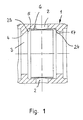
- Fig. 1 shows a cylindrical sleeve 1 of a switching or proportional valve. Since such valves are known, they will be described below also not described in detail.
- the sleeve 1 has over its circumference distributes several holes 2 through which hydraulic medium in a central bore 3 of the sleeve 1 can flow.
- an annular groove 5 In the inner wall 4 of the sleeve 1 is an annular groove 5, in which the holes 2 open.
- the holes 2 can be closed with a closing element 6 which consists of a ring-shaped band.
- the axial Width of the closing element 6 is slightly smaller than the axial Width of the annular groove 5, which has relatively small radial depth.
- the diameter of the closing element 6 can be described in more detail Way to close or open the holes 2 increases or reduced in size.
- Fig. 2 shows a check valve
- the closing element 6 in a Ring groove 7 is located, which is provided on the outside of the valve sleeve 1 is.
- an additional sleeve 8 which on the Valve sleeve 1 is seated.
- the additional sleeve 8 has holes 9, which are advantageous are aligned with the holes 2 in the valve sleeve 1.
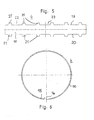
- FIGS. 3 and 4 show a first embodiment of the closing element 6. It is characterized by a strip-shaped tape 10 with rectangular Outline formed, the formation of the closing element 6 in a Ring shape is bent. From the band 10 are single resilient Flaps 11 partially punched out, with which the corresponding 2 holes in the valve sleeve 1 can be closed. As Fig. 3 shows the flaps 11 are in the longitudinal direction of the belt 10th at a distance one behind the other. The flaps 11 are advantageously the same formed and have a half width of the belt 10 lying Foot 12, which merges into a circular closing part 13. about the foot 12, the flap 11 is connected to the material of the belt 10. Thus, the flap 11 for closing and opening the holes 2 can perform the necessary movements are the Foot 12 and the closing part 13 through a gap 14 from the residual material the band 10 separated.
- the band 10 is bent into a ring.
- the two band ends 15, 16 are at a small distance from each other.
- the bent band 10 is thus installed in the valve sleeve, that the flaps 11 are equal to the holes 2.
- the resilient flaps 11 As the flaps 11 separated by the column 14 from the residual material of the belt 10 are, in the bending operation of the band 10, the resilient flaps 11 not bent or not to the same extent. As a consequence, that the flaps 11 under bias so on the valve sleeve. 1 abut that the closing part 13 of the flaps 11, the holes. 2 closes.
- the flaps 11 to the same extent to bend the band 10 so that the flaps 11 are not over the band 10 protrude.
- the entire band is under bias at the bottom 17 of the annular groove 5 (FIG. 1) or at the inside 18 the additional sleeve 8 ( Figure 2). In this case, close the Flaps 11, the holes 9 in the additional sleeve. 8
- the closing element 6 may also consist of a band 10, the has no resilient flaps 11. In this case, that forms Closing element 6 at the same time a spring element, the opening and Closing the holes 2 and 9 elastically expanded in diameter or reduced. In one position are the holes 2 or 9 closed while released in the other position become.
- the spring force of the band bent into a ring 10 is adapted to the particular application of the valve. The Spring force is chosen so that the holes 2, 9 at a given Pressure of the hydraulic medium can be released by the diameter of the closing element increases or decreases becomes.
- FIGS. 5 and 6 show an embodiment in which the band 10 no partially punched flaps 11 has. Instead, it is the rectangular strip-shaped band 10 at its two longitudinal sides 19, 20 provided with projections 21 spaced along the Longitudinal sides 19, 20 are provided. Advantageously, the projections are 21 with the same distance behind each other. The at the two Longitudinal sides 19, 20 provided projections 21 are advantageous at the same height. Between the projections 21 are free spaces 22 formed.
- the band 10 again becomes one Ring bent and inserted into the respective valve in a bent state.
- the projections 21 serve in the installed position of the closing element 6 as lateral stops, with which they are on the side walls 23, 24 of the annular groove 5 (FIG. 1) or on the side walls 25, 26 of the annular groove 7 (Fig. 2) come to rest.
- the entire volume 10 serves in this case as a closing element with which the holes 2, 9 can be released or closed.
- the diameter of the closing element 6 is increased or reduced.
- the one end 15 of the band 10 is bent radially inwards (FIG. 6).
- the two ends 15, 16 of the band 10 can, as shown in Fig. 6, have a distance from each other in the installation position.
- overlap the ends 15, 16 of the belt 10th beneficial each other.
- the band 10 also only from a rectangular strip without projections 21 be formed. Also in this case, the band 10 forms in a ring bent state both the closing element and the Spring element.
- the ring springs in a basic position back, in which he on the valve sleeve 1 (Fig. 1) or at the additional Sleeve 8 (Fig. 2) can rest under its biasing force. It but is also possible, the closing element 6 in such a way that it in its initial position floating in the respective annular groove 5, 7th lies.
- the closing element 6 is in the described embodiments formed by a spring band, which bent into a ring is, the two ends 15, 16 are spaced from each other. This allows the ring reliably in the closed or in the release position be elastically deformed.
- the holes 2, 9 have advantageous circular outline.
- the sealing edge is accordingly circular.
- the closing element 6 With the closing element 6, all holes 2, 9 on the circumference closed or opened the valve.
- the closing element 6 can also be designed so that there is only one or only one Part of the holes can close or release.
- the closing element consists of a band 10, preferably a spring band, is made, it takes in the installation position little Room to complete.
- the closing element 6 can therefore in the annular groove 5, 7 of the valve can be comfortably accommodated, the only small radial Has depth.
- the closing element 6 can in the P, T, A or B channel are housed, preferably in the pressure channel P, the is formed by a corresponding annular groove of the valve.
- the described check valve can also slide holes be built by control blocks, preferably with camshaft adjusters be used.
- the closing element 6 can in the installed position by a (not shown) Secure anti-rotation lock against rotation.
- the anti-twist device For example, by a pin, a notch and the like.
Landscapes
- Engineering & Computer Science (AREA)
- General Engineering & Computer Science (AREA)
- Mechanical Engineering (AREA)
- Check Valves (AREA)
- Reciprocating Pumps (AREA)
- Compressor (AREA)
- Pens And Brushes (AREA)
- Taps Or Cocks (AREA)
Applications Claiming Priority (2)
| Application Number | Priority Date | Filing Date | Title |
|---|---|---|---|
| DE10143433 | 2001-09-05 | ||
| DE10143433A DE10143433B4 (de) | 2001-09-05 | 2001-09-05 | Proportionalventil |
Publications (3)
| Publication Number | Publication Date |
|---|---|
| EP1291563A2 true EP1291563A2 (fr) | 2003-03-12 |
| EP1291563A3 EP1291563A3 (fr) | 2003-12-03 |
| EP1291563B1 EP1291563B1 (fr) | 2006-07-19 |
Family
ID=7697752
Family Applications (1)
| Application Number | Title | Priority Date | Filing Date |
|---|---|---|---|
| EP02018813A Expired - Lifetime EP1291563B1 (fr) | 2001-09-05 | 2002-08-23 | Soupape non-retour et vanne avec une telle soupape non-retour |
Country Status (6)
| Country | Link |
|---|---|
| US (1) | US6899126B2 (fr) |
| EP (1) | EP1291563B1 (fr) |
| AT (1) | ATE333617T1 (fr) |
| DE (2) | DE10143433B4 (fr) |
| ES (1) | ES2267908T3 (fr) |
| PT (1) | PT1291563E (fr) |
Cited By (23)
| Publication number | Priority date | Publication date | Assignee | Title |
|---|---|---|---|---|
| DE102005013085B3 (de) * | 2005-03-18 | 2006-06-01 | Hydraulik-Ring Gmbh | Ventil mit Rückschlagventil |
| WO2006136258A1 (fr) | 2005-06-22 | 2006-12-28 | Schaeffler Kg | Soupape de commande pour un dispositif de reglage variable des temps de commande de soupapes d'echange des gaz d'un moteur a combustion interne |
| WO2007068586A1 (fr) * | 2005-12-16 | 2007-06-21 | Schaeffler Kg | Conduite d'alimentation de dispositif de reglage d'arbre a cames |
| WO2007131866A1 (fr) * | 2006-05-13 | 2007-11-22 | Schaeffler Kg | Soupape de commande pour un dispositif de réglage d'arbre à cames |
| WO2009089960A1 (fr) * | 2008-01-16 | 2009-07-23 | Schaeffler Kg | Soupape de commande hydraulique à clapet antiretour intégré |
| WO2010139522A1 (fr) * | 2009-06-05 | 2010-12-09 | Schaeffler Technologies Gmbh & Co. Kg | Soupape de commande pour commander des flux d'agent de pression avec clapet anti-retour intégré |
| DE102010009401A1 (de) | 2010-02-26 | 2011-09-01 | Schaeffler Technologies Gmbh & Co. Kg | Proportionalventil, insbesondere für einen Nockenwellenversteller |
| DE102010018200A1 (de) | 2010-04-26 | 2011-10-27 | Schaeffler Technologies Gmbh & Co. Kg | Steuerventil, insbesondere Proportionalventil |
| EP2386731A1 (fr) * | 2010-05-03 | 2011-11-16 | Hydraulik-Ring GmbH | Soupape hydraulique |
| EP2503201A1 (fr) * | 2011-03-22 | 2012-09-26 | Incova Technologies, Inc. | Agencement de soupape hydraulique avec élément de soupape anti-retour annulaire |
| EP2441928A4 (fr) * | 2009-06-10 | 2013-01-02 | Nittan Valva | Dispositif de réglage de jeu hydraulique pour moteur à combustion interne |
| DE102011087664A1 (de) * | 2011-12-02 | 2013-06-06 | Continental Automotive Gmbh | Ventilanordnung |
| CN103670565A (zh) * | 2012-09-10 | 2014-03-26 | 株式会社电装 | 滑阀 |
| WO2016001166A1 (fr) * | 2014-07-03 | 2016-01-07 | Robert Bosch Gmbh | Soupape de décharge destinée à un système d'alimentation en carburant et procédé de production d'une telle soupape |
| FR3032748A1 (fr) * | 2015-02-12 | 2016-08-19 | Peugeot Citroen Automobiles Sa | Dispositif de blocage de soupape commandee par linguet |
| DE102012201548B4 (de) | 2012-02-02 | 2019-05-16 | Schaeffler Technologies AG & Co. KG | Steuerventil für hydraulische Medien |
| EP3530892A1 (fr) * | 2018-02-21 | 2019-08-28 | ECO Holding 1 GmbH | Soupape hydraulique pour un dispositif de réglage de moteur oscillant d'un arbre à cames |
| CN110192008A (zh) * | 2017-01-19 | 2019-08-30 | 株式会社电装 | 气门正时调整装置 |
| DE102019105607A1 (de) * | 2019-03-06 | 2020-01-09 | Schaeffler Technologies AG & Co. KG | Hydraulisches Abstützelement für einen Ventiltrieb einer Brennkraftmaschine |
| WO2020007709A1 (fr) * | 2018-07-04 | 2020-01-09 | Delphi Automotive Systems Luxembourg Sa | Dispositif de commande d'un dephaseur d'arbre a cames |
| FR3093345A1 (fr) * | 2019-03-01 | 2020-09-04 | Delphi Automotive Systems Luxembourg S.A. | Ensemble tiroir |
| US10895328B2 (en) | 2018-07-30 | 2021-01-19 | Danfoss Power Solutions Aps | Hydraulic steering unit |
| US12134976B2 (en) * | 2022-03-07 | 2024-11-05 | Mikuni Corporation | Fluid control valve and valve timing changing device |
Families Citing this family (39)
| Publication number | Priority date | Publication date | Assignee | Title |
|---|---|---|---|---|
| US7000580B1 (en) | 2004-09-28 | 2006-02-21 | Borgwarner Inc. | Control valves with integrated check valves |
| DE102004054474B3 (de) * | 2004-11-11 | 2006-06-08 | Zf Friedrichshafen Ag | Schwingungsdämpfer mit verstellbarer Dämpfkraft |
| DE102004057633B4 (de) * | 2004-11-30 | 2014-05-15 | Hofer Mechatronik Gmbh | Rückschlagventil für einen Nockenwellenversteller |
| US6971354B1 (en) | 2004-12-20 | 2005-12-06 | Borgwarner Inc. | Variable camshaft timing system with remotely located control system |
| JP5188982B2 (ja) * | 2005-12-13 | 2013-04-24 | ボーグワーナー インコーポレーテッド | バンド式チェックバルブを有する液圧テンショナ |
| EP2522820B1 (fr) * | 2007-07-02 | 2017-08-09 | BorgWarner Inc. | Came concentrique avec clapets anti-retour dans la bobine pour un déphaseur |
| DE102007050447B4 (de) | 2007-10-19 | 2017-01-12 | Hilite Germany Gmbh | Hydraulisches Cartridgeventil mit Sieb |
| DE102008006178A1 (de) * | 2008-01-26 | 2009-07-30 | Schaeffler Kg | Druckmitteleinsatz für ein Steuerventil in einer hydraulischen Stellvorrichtung |
| US8584634B2 (en) * | 2008-09-19 | 2013-11-19 | Borgwarner Inc. | Phaser built into a camshaft or concentric camshafts |
| US8118574B1 (en) | 2008-10-03 | 2012-02-21 | Aci Services, Inc. | Radial suction valve assembly for a compressor |
| US8127790B2 (en) * | 2009-03-25 | 2012-03-06 | Husco Automotive Holdings Llc | Hydraulic valve with a filter and check valve band |
| DE102009022869A1 (de) * | 2009-05-27 | 2010-12-09 | Hydraulik-Ring Gmbh | Flügelzellennockenwellenverstellersystem |
| DE102009042889A1 (de) * | 2009-09-24 | 2011-06-09 | Hydraulik-Ring Gmbh | Cartridgeventil mit einer Buchse |
| DE102009050779B4 (de) | 2009-10-27 | 2016-05-04 | Hilite Germany Gmbh | Schwenkmotornockenwellenversteller mit einer Reibscheibe und Montageverfahren |
| DE102009052841A1 (de) * | 2009-11-13 | 2011-05-19 | Hydraulik-Ring Gmbh | Nockenwelleneinsatz |
| DE102010045358A1 (de) | 2010-04-10 | 2011-10-13 | Hydraulik-Ring Gmbh | Schwenkmotornockenwellenversteller mit einem Hydraulikventil |
| US8984853B2 (en) | 2010-05-21 | 2015-03-24 | United Technologies Corporation | Accessing a valve assembly of a turbomachine |
| US8596080B2 (en) * | 2010-05-27 | 2013-12-03 | Delphi Technologies, Inc. | Air conditioning system having an improved internal heat exchanger |
| DE102010061337B4 (de) | 2010-12-20 | 2015-07-09 | Hilite Germany Gmbh | Hydraulikventil für einen Schwenkmotorversteller |
| DE102011000591B4 (de) | 2011-02-09 | 2018-03-08 | Hilite Germany Gmbh | Zentralventil für einen Schwenkmotorversteller |
| US9051809B2 (en) | 2011-04-29 | 2015-06-09 | Weatherford Technology Holdings, Llc | Casing relief valve |
| CA2834230C (fr) | 2011-04-29 | 2016-06-14 | Weatherford/Lamb, Inc. | Raccord de decharge de pression de l'espace annulaire |
| JP5360173B2 (ja) | 2011-09-15 | 2013-12-04 | 株式会社デンソー | バルブタイミング調整装置 |
| DE102013004850B4 (de) * | 2013-03-05 | 2018-03-29 | Iwis Motorsysteme Gmbh & Co. Kg | Spannvorrichtung mit Blattfedermembran |
| US9797276B2 (en) | 2013-03-11 | 2017-10-24 | Husco Automotive Holdings Llc | System for varying cylinder valve timing in an internal combustion engine |
| US9115610B2 (en) * | 2013-03-11 | 2015-08-25 | Husco Automotive Holdings Llc | System for varying cylinder valve timing in an internal combustion engine |
| EP3047181B1 (fr) * | 2013-09-17 | 2019-03-13 | Fisher & Paykel Healthcare Limited | Soupape avec élément interne |
| DE102014101236B4 (de) | 2014-01-31 | 2017-06-08 | Hilite Germany Gmbh | Hydraulikventil für einen Schwenkmotorversteller einer Nockenwelle |
| JP6384216B2 (ja) * | 2014-09-08 | 2018-09-05 | 株式会社デンソー | 油圧制御弁 |
| CN104454062A (zh) * | 2014-12-01 | 2015-03-25 | 绵阳富临精工机械股份有限公司 | 一种用于机油控制阀的带限位机构的单向阀 |
| DE102014118794A1 (de) | 2014-12-17 | 2016-06-23 | Hilite Germany Gmbh | Sieb für ein hydraulisches Ventil |
| CN112682122B (zh) | 2016-10-06 | 2022-09-09 | 博格华纳公司 | 用于可变凸轮正时系统的双瓣阀 |
| US11111827B2 (en) | 2016-10-06 | 2021-09-07 | Borgwarner, Inc. | Double flapper valve for a variable cam timing system |
| JP6790925B2 (ja) * | 2017-03-07 | 2020-11-25 | 株式会社デンソー | 作動油制御弁、および、これを用いたバルブタイミング調整装置 |
| JP6780573B2 (ja) * | 2017-04-21 | 2020-11-04 | 株式会社デンソー | バルブタイミング調整装置 |
| DE102018102758B4 (de) * | 2018-02-07 | 2020-01-16 | Kendrion (Villingen) Gmbh | Feder für ein Rückschlagventil, Rückschlagventil mit einer derartigen Feder, regelbarer Schwingungsdämpfer mit einem solchen Rückschlagventil sowie Kraftfahrzeug mit einem derartigen regelbaren Schwingungsdämpfer |
| JP6879243B2 (ja) | 2018-03-22 | 2021-06-02 | 株式会社デンソー | 弁装置 |
| US11092045B1 (en) * | 2020-03-22 | 2021-08-17 | ECO Holding 1 GmbH | Control valve for cam phaser and method for mounting the control valve |
| DE102023102712A1 (de) * | 2023-02-03 | 2024-08-08 | Eto Magnetic Gmbh | Rückschlagventil, bidirektionale Dämpfervorrichtung und Verfahren |
Family Cites Families (15)
| Publication number | Priority date | Publication date | Assignee | Title |
|---|---|---|---|---|
| DE135322C (fr) * | 1900-01-01 | |||
| US2649105A (en) * | 1953-08-18 | Self-draining pipe joint | ||
| US894286A (en) * | 1908-04-10 | 1908-07-28 | Frederick C Reineking | Air-intake regulator for carbureters. |
| FR525481A (fr) * | 1920-10-01 | 1921-09-22 | Alphonse Papin | Soupape à ruban |
| US1860163A (en) * | 1930-04-21 | 1932-05-24 | Binks Mfg Co | Valve assembly for air-compressing cylinders |
| US2781059A (en) * | 1954-01-08 | 1957-02-12 | Gen Motors Corp | Flow control device |
| US2918941A (en) * | 1957-12-02 | 1959-12-29 | Orenda Engines Ltd | Pressure relief blow-out device |
| US3459217A (en) * | 1966-03-21 | 1969-08-05 | Houdaille Industries Inc | Garter check valve |
| US3783590A (en) * | 1970-07-09 | 1974-01-08 | A Allen | Filter-silencer for pneumatic devices |
| DE2043002A1 (de) * | 1970-08-29 | 1972-03-02 | Ishkewich M | Druck und Saugventil |
| US3882891A (en) * | 1974-06-19 | 1975-05-13 | Abex Corp | Check valve |
| DE2757490C3 (de) * | 1977-12-22 | 1980-09-11 | 1000 Berlin | Druckventil |
| JPS582490A (ja) * | 1981-06-29 | 1983-01-08 | Sanden Corp | スクロ−ル型圧縮機 |
| GB2161583B (en) | 1984-07-10 | 1988-01-27 | Prestcold Ltd | Reed valve |
| US5323806A (en) * | 1992-03-26 | 1994-06-28 | Matsushita Electric Works, Ltd. | Constant-speed exhaust valve device for hemadynamometer |
-
2001
- 2001-09-05 DE DE10143433A patent/DE10143433B4/de not_active Expired - Fee Related
-
2002
- 2002-08-23 DE DE50207545T patent/DE50207545D1/de not_active Expired - Lifetime
- 2002-08-23 US US10/064,861 patent/US6899126B2/en not_active Expired - Lifetime
- 2002-08-23 PT PT02018813T patent/PT1291563E/pt unknown
- 2002-08-23 ES ES02018813T patent/ES2267908T3/es not_active Expired - Lifetime
- 2002-08-23 EP EP02018813A patent/EP1291563B1/fr not_active Expired - Lifetime
- 2002-08-23 AT AT02018813T patent/ATE333617T1/de not_active IP Right Cessation
Non-Patent Citations (1)
| Title |
|---|
| None |
Cited By (40)
| Publication number | Priority date | Publication date | Assignee | Title |
|---|---|---|---|---|
| US7600531B2 (en) | 2005-03-18 | 2009-10-13 | Hydraulik-Ring Gmbh | Valve with check valve |
| EP1703184A1 (fr) * | 2005-03-18 | 2006-09-20 | Hydraulik-Ring GmbH | Soupape avec clapet de retenue |
| DE102005013085B3 (de) * | 2005-03-18 | 2006-06-01 | Hydraulik-Ring Gmbh | Ventil mit Rückschlagventil |
| WO2006136258A1 (fr) | 2005-06-22 | 2006-12-28 | Schaeffler Kg | Soupape de commande pour un dispositif de reglage variable des temps de commande de soupapes d'echange des gaz d'un moteur a combustion interne |
| US8684041B2 (en) | 2005-06-22 | 2014-04-01 | Schaeffler Technologies Gmbh & Co. Kg | Control valve for a device for variably adjusting the valve timing for gas exchange valves in an internal combustion engine |
| WO2007068586A1 (fr) * | 2005-12-16 | 2007-06-21 | Schaeffler Kg | Conduite d'alimentation de dispositif de reglage d'arbre a cames |
| CN101331297B (zh) * | 2005-12-16 | 2011-02-16 | 谢夫勒科技有限两合公司 | 凸轮轴调节器输入管道 |
| US8146549B2 (en) | 2005-12-16 | 2012-04-03 | Schaeffler Technologies Gmbh & Co. Kg | Feeder for a camshaft adjuster |
| WO2007131866A1 (fr) * | 2006-05-13 | 2007-11-22 | Schaeffler Kg | Soupape de commande pour un dispositif de réglage d'arbre à cames |
| US8316889B2 (en) | 2006-05-13 | 2012-11-27 | Schaeffler Technologies AG & Co. KG | Control valve for a camshaft adjuster |
| WO2009089960A1 (fr) * | 2008-01-16 | 2009-07-23 | Schaeffler Kg | Soupape de commande hydraulique à clapet antiretour intégré |
| WO2010139522A1 (fr) * | 2009-06-05 | 2010-12-09 | Schaeffler Technologies Gmbh & Co. Kg | Soupape de commande pour commander des flux d'agent de pression avec clapet anti-retour intégré |
| US8757114B2 (en) | 2009-06-05 | 2014-06-24 | Schaeffler Technologies Gmbh & Co. Kg | Control valve for controlling pressure-medium flows comprising an integrated check valve |
| EP2441928A4 (fr) * | 2009-06-10 | 2013-01-02 | Nittan Valva | Dispositif de réglage de jeu hydraulique pour moteur à combustion interne |
| WO2011104058A1 (fr) | 2010-02-26 | 2011-09-01 | Schaeffler Technologies Gmbh & Co. Kg | Valve proportionnelle, en particulier pour un dispositif de réglage d'arbre à cames |
| DE102010009401A1 (de) | 2010-02-26 | 2011-09-01 | Schaeffler Technologies Gmbh & Co. Kg | Proportionalventil, insbesondere für einen Nockenwellenversteller |
| WO2011134750A1 (fr) | 2010-04-26 | 2011-11-03 | Schaeffler Technologies Gmbh & Co. Kg | Soupape de commande munie d'une lame de ressort incurvée servant de soupape de non-retour |
| DE102010018200A1 (de) | 2010-04-26 | 2011-10-27 | Schaeffler Technologies Gmbh & Co. Kg | Steuerventil, insbesondere Proportionalventil |
| EP2386731A1 (fr) * | 2010-05-03 | 2011-11-16 | Hydraulik-Ring GmbH | Soupape hydraulique |
| EP2503201A1 (fr) * | 2011-03-22 | 2012-09-26 | Incova Technologies, Inc. | Agencement de soupape hydraulique avec élément de soupape anti-retour annulaire |
| DE102011087664A1 (de) * | 2011-12-02 | 2013-06-06 | Continental Automotive Gmbh | Ventilanordnung |
| DE102011087664B4 (de) * | 2011-12-02 | 2014-03-20 | Continental Automotive Gmbh | Ventilanordnung |
| DE102012201548B4 (de) | 2012-02-02 | 2019-05-16 | Schaeffler Technologies AG & Co. KG | Steuerventil für hydraulische Medien |
| CN103670565A (zh) * | 2012-09-10 | 2014-03-26 | 株式会社电装 | 滑阀 |
| CN103670565B (zh) * | 2012-09-10 | 2017-09-12 | 株式会社电装 | 滑阀 |
| CN106662051A (zh) * | 2014-07-03 | 2017-05-10 | 罗伯特·博世有限公司 | 用于燃料供给系统的溢流阀和用于制造这种阀的方法 |
| WO2016001166A1 (fr) * | 2014-07-03 | 2016-01-07 | Robert Bosch Gmbh | Soupape de décharge destinée à un système d'alimentation en carburant et procédé de production d'une telle soupape |
| CN106662051B (zh) * | 2014-07-03 | 2019-08-30 | 罗伯特·博世有限公司 | 用于燃料供给系统的溢流阀和用于制造这种阀的方法 |
| FR3032748A1 (fr) * | 2015-02-12 | 2016-08-19 | Peugeot Citroen Automobiles Sa | Dispositif de blocage de soupape commandee par linguet |
| CN110192008B (zh) * | 2017-01-19 | 2022-03-04 | 株式会社电装 | 气门正时调整装置 |
| CN110192008A (zh) * | 2017-01-19 | 2019-08-30 | 株式会社电装 | 气门正时调整装置 |
| EP3530892A1 (fr) * | 2018-02-21 | 2019-08-28 | ECO Holding 1 GmbH | Soupape hydraulique pour un dispositif de réglage de moteur oscillant d'un arbre à cames |
| US11300017B2 (en) | 2018-02-21 | 2022-04-12 | ECO Holding 1 GmbH | Hydraulic valve for a cam phaser |
| WO2020007709A1 (fr) * | 2018-07-04 | 2020-01-09 | Delphi Automotive Systems Luxembourg Sa | Dispositif de commande d'un dephaseur d'arbre a cames |
| CN112352091A (zh) * | 2018-07-04 | 2021-02-09 | 德尔福汽车系统卢森堡有限公司 | 控制凸轮轴相位器的装置 |
| FR3083569A1 (fr) * | 2018-07-04 | 2020-01-10 | Delphi Automotive Systems Luxembourg Sa | Dispositif de commande d'un dephaseur d'arbre a cames |
| US10895328B2 (en) | 2018-07-30 | 2021-01-19 | Danfoss Power Solutions Aps | Hydraulic steering unit |
| FR3093345A1 (fr) * | 2019-03-01 | 2020-09-04 | Delphi Automotive Systems Luxembourg S.A. | Ensemble tiroir |
| DE102019105607A1 (de) * | 2019-03-06 | 2020-01-09 | Schaeffler Technologies AG & Co. KG | Hydraulisches Abstützelement für einen Ventiltrieb einer Brennkraftmaschine |
| US12134976B2 (en) * | 2022-03-07 | 2024-11-05 | Mikuni Corporation | Fluid control valve and valve timing changing device |
Also Published As
| Publication number | Publication date |
|---|---|
| DE10143433A1 (de) | 2003-04-03 |
| DE50207545D1 (de) | 2006-08-31 |
| US6899126B2 (en) | 2005-05-31 |
| PT1291563E (pt) | 2006-11-30 |
| US20030070713A1 (en) | 2003-04-17 |
| ATE333617T1 (de) | 2006-08-15 |
| EP1291563B1 (fr) | 2006-07-19 |
| ES2267908T3 (es) | 2007-03-16 |
| EP1291563A3 (fr) | 2003-12-03 |
| DE10143433B4 (de) | 2013-09-26 |
Similar Documents
| Publication | Publication Date | Title |
|---|---|---|
| DE10143433B4 (de) | Proportionalventil | |
| DE69824615T2 (de) | Verbesserter tropfbewässerungsauslass | |
| EP1084358B1 (fr) | Double vanne de securite magnetique | |
| DE602005001726T2 (de) | Magnetventil zur Installation auf einem unter Gasdruck stehenden Flüssigkeitsbehälter | |
| DE2626236A1 (de) | Ventilaufbau | |
| EP0067403B1 (fr) | Robinet avec boisseau sphérique | |
| DE4236481C2 (de) | Rückschlagventil | |
| DE19810391A1 (de) | Druckreduzierventil | |
| DE3425750A1 (de) | Ausdehnbarer absperrschieber | |
| DE2110065A1 (de) | Ventil und Verfahren zu dessen Herstellung | |
| DE1459163B1 (de) | Obentürschliesser | |
| DE1550177B1 (de) | Kegelhahn mit im Kueken mit Spiel angeordneten Dichtungsplatten | |
| DE4214500C2 (de) | Umgehungs- oder Überdruckventil zum Einbau in Flüssigkeit führende Einrichtungen, insbesondere Flüssigkeitsfilter | |
| DE2349772C2 (de) | Absperrorgan | |
| EP0110289B1 (fr) | Soupape d'équilibrage | |
| DE3901444C2 (de) | Steuerbares Rückschlagventil | |
| DE2404174C3 (fr) | ||
| DE102014214610A1 (de) | Nockenwellenverstellvorrichtung für eine Brennkraftmaschine | |
| DE2008092B2 (de) | VentUeinrichtung zur hydraulischen Blockierung | |
| CH657193A5 (de) | Verschluss fuer eine kupplung. | |
| DE3005768A1 (de) | Ueberdruckventil | |
| EP3899277B1 (fr) | Soupape à clapet | |
| DE2449443A1 (de) | Rueckschlagventil | |
| DE202005016282U1 (de) | Ventilglied und damit ausgestattetes Ventil | |
| EP0634529B1 (fr) | Disconnecteur de tuyau |
Legal Events
| Date | Code | Title | Description |
|---|---|---|---|
| PUAI | Public reference made under article 153(3) epc to a published international application that has entered the european phase |
Free format text: ORIGINAL CODE: 0009012 |
|
| AK | Designated contracting states |
Kind code of ref document: A2 Designated state(s): AT BE BG CH CY CZ DE DK EE ES FI FR GB GR IE IT LI LU MC NL PT SE SK TR Designated state(s): AT BE BG CH CY CZ DE DK EE ES FI FR GB GR IE IT LI LU MC NL PT SE SK TR |
|
| AX | Request for extension of the european patent |
Extension state: AL LT LV MK RO SI |
|
| PUAL | Search report despatched |
Free format text: ORIGINAL CODE: 0009013 |
|
| AK | Designated contracting states |
Kind code of ref document: A3 Designated state(s): AT BE BG CH CY CZ DE DK EE ES FI FR GB GR IE IT LI LU MC NL PT SE SK TR |
|
| AX | Request for extension of the european patent |
Extension state: AL LT LV MK RO SI |
|
| RIN1 | Information on inventor provided before grant (corrected) |
Inventor name: LIPPERT, LORENZ Inventor name: WEIGAND, BERND Inventor name: CORNEA, MARIUS Inventor name: PALESCH, EDWIN Inventor name: SLUKA, GEROLD |
|
| 17P | Request for examination filed |
Effective date: 20040503 |
|
| 17Q | First examination report despatched |
Effective date: 20040528 |
|
| AKX | Designation fees paid |
Designated state(s): AT BE BG CH CY CZ DE DK EE ES FI FR GB GR IE IT LI LU MC NL PT SE SK TR |
|
| GRAP | Despatch of communication of intention to grant a patent |
Free format text: ORIGINAL CODE: EPIDOSNIGR1 |
|
| RAP1 | Party data changed (applicant data changed or rights of an application transferred) |
Owner name: HYDRAULIK-RING GMBH |
|
| GRAC | Information related to communication of intention to grant a patent modified |
Free format text: ORIGINAL CODE: EPIDOSCIGR1 |
|
| GRAS | Grant fee paid |
Free format text: ORIGINAL CODE: EPIDOSNIGR3 |
|
| GRAA | (expected) grant |
Free format text: ORIGINAL CODE: 0009210 |
|
| AK | Designated contracting states |
Kind code of ref document: B1 Designated state(s): AT BE BG CH CY CZ DE DK EE ES FI FR GB GR IE IT LI LU MC NL PT SE SK TR |
|
| PG25 | Lapsed in a contracting state [announced via postgrant information from national office to epo] |
Ref country code: IT Free format text: LAPSE BECAUSE OF FAILURE TO SUBMIT A TRANSLATION OF THE DESCRIPTION OR TO PAY THE FEE WITHIN THE PRESCRIBED TIME-LIMIT;WARNING: LAPSES OF ITALIAN PATENTS WITH EFFECTIVE DATE BEFORE 2007 MAY HAVE OCCURRED AT ANY TIME BEFORE 2007. THE CORRECT EFFECTIVE DATE MAY BE DIFFERENT FROM THE ONE RECORDED. Effective date: 20060719 Ref country code: IE Free format text: LAPSE BECAUSE OF FAILURE TO SUBMIT A TRANSLATION OF THE DESCRIPTION OR TO PAY THE FEE WITHIN THE PRESCRIBED TIME-LIMIT Effective date: 20060719 Ref country code: NL Free format text: LAPSE BECAUSE OF FAILURE TO SUBMIT A TRANSLATION OF THE DESCRIPTION OR TO PAY THE FEE WITHIN THE PRESCRIBED TIME-LIMIT Effective date: 20060719 Ref country code: SK Free format text: LAPSE BECAUSE OF FAILURE TO SUBMIT A TRANSLATION OF THE DESCRIPTION OR TO PAY THE FEE WITHIN THE PRESCRIBED TIME-LIMIT Effective date: 20060719 Ref country code: FI Free format text: LAPSE BECAUSE OF FAILURE TO SUBMIT A TRANSLATION OF THE DESCRIPTION OR TO PAY THE FEE WITHIN THE PRESCRIBED TIME-LIMIT Effective date: 20060719 |
|
| REG | Reference to a national code |
Ref country code: GB Ref legal event code: FG4D Free format text: NOT ENGLISH |
|
| REG | Reference to a national code |
Ref country code: CH Ref legal event code: EP |
|
| REG | Reference to a national code |
Ref country code: IE Ref legal event code: FG4D Free format text: LANGUAGE OF EP DOCUMENT: GERMAN |
|
| PG25 | Lapsed in a contracting state [announced via postgrant information from national office to epo] |
Ref country code: LI Free format text: LAPSE BECAUSE OF NON-PAYMENT OF DUE FEES Effective date: 20060831 Ref country code: CH Free format text: LAPSE BECAUSE OF NON-PAYMENT OF DUE FEES Effective date: 20060831 Ref country code: MC Free format text: LAPSE BECAUSE OF NON-PAYMENT OF DUE FEES Effective date: 20060831 Ref country code: BE Free format text: LAPSE BECAUSE OF NON-PAYMENT OF DUE FEES Effective date: 20060831 |
|
| REF | Corresponds to: |
Ref document number: 50207545 Country of ref document: DE Date of ref document: 20060831 Kind code of ref document: P |
|
| GBT | Gb: translation of ep patent filed (gb section 77(6)(a)/1977) |
Effective date: 20060923 |
|
| PG25 | Lapsed in a contracting state [announced via postgrant information from national office to epo] |
Ref country code: DK Free format text: LAPSE BECAUSE OF FAILURE TO SUBMIT A TRANSLATION OF THE DESCRIPTION OR TO PAY THE FEE WITHIN THE PRESCRIBED TIME-LIMIT Effective date: 20061019 Ref country code: BG Free format text: LAPSE BECAUSE OF FAILURE TO SUBMIT A TRANSLATION OF THE DESCRIPTION OR TO PAY THE FEE WITHIN THE PRESCRIBED TIME-LIMIT Effective date: 20061019 |
|
| REG | Reference to a national code |
Ref country code: SE Ref legal event code: TRGR |
|
| REG | Reference to a national code |
Ref country code: PT Ref legal event code: SC4A Free format text: AVAILABILITY OF NATIONAL TRANSLATION Effective date: 20060927 |
|
| NLV1 | Nl: lapsed or annulled due to failure to fulfill the requirements of art. 29p and 29m of the patents act | ||
| ET | Fr: translation filed | ||
| REG | Reference to a national code |
Ref country code: IE Ref legal event code: FD4D |
|
| REG | Reference to a national code |
Ref country code: ES Ref legal event code: FG2A Ref document number: 2267908 Country of ref document: ES Kind code of ref document: T3 |
|
| REG | Reference to a national code |
Ref country code: CH Ref legal event code: PL |
|
| PLBE | No opposition filed within time limit |
Free format text: ORIGINAL CODE: 0009261 |
|
| STAA | Information on the status of an ep patent application or granted ep patent |
Free format text: STATUS: NO OPPOSITION FILED WITHIN TIME LIMIT |
|
| 26N | No opposition filed |
Effective date: 20070420 |
|
| PG25 | Lapsed in a contracting state [announced via postgrant information from national office to epo] |
Ref country code: AT Free format text: LAPSE BECAUSE OF NON-PAYMENT OF DUE FEES Effective date: 20060823 |
|
| BERE | Be: lapsed |
Owner name: HYDRAULIK-RING G.M.B.H. Effective date: 20060831 |
|
| PG25 | Lapsed in a contracting state [announced via postgrant information from national office to epo] |
Ref country code: GR Free format text: LAPSE BECAUSE OF FAILURE TO SUBMIT A TRANSLATION OF THE DESCRIPTION OR TO PAY THE FEE WITHIN THE PRESCRIBED TIME-LIMIT Effective date: 20061020 |
|
| PG25 | Lapsed in a contracting state [announced via postgrant information from national office to epo] |
Ref country code: EE Free format text: LAPSE BECAUSE OF FAILURE TO SUBMIT A TRANSLATION OF THE DESCRIPTION OR TO PAY THE FEE WITHIN THE PRESCRIBED TIME-LIMIT Effective date: 20060719 |
|
| PG25 | Lapsed in a contracting state [announced via postgrant information from national office to epo] |
Ref country code: TR Free format text: LAPSE BECAUSE OF FAILURE TO SUBMIT A TRANSLATION OF THE DESCRIPTION OR TO PAY THE FEE WITHIN THE PRESCRIBED TIME-LIMIT Effective date: 20060719 Ref country code: LU Free format text: LAPSE BECAUSE OF NON-PAYMENT OF DUE FEES Effective date: 20060823 |
|
| PG25 | Lapsed in a contracting state [announced via postgrant information from national office to epo] |
Ref country code: CY Free format text: LAPSE BECAUSE OF FAILURE TO SUBMIT A TRANSLATION OF THE DESCRIPTION OR TO PAY THE FEE WITHIN THE PRESCRIBED TIME-LIMIT Effective date: 20060719 |
|
| REG | Reference to a national code |
Ref country code: DE Ref legal event code: R081 Ref document number: 50207545 Country of ref document: DE Owner name: HILITE GERMANY GMBH, DE Free format text: FORMER OWNER: HYDRAULIK-RING GMBH, 97828 MARKTHEIDENFELD, DE Effective date: 20130521 |
|
| PGFP | Annual fee paid to national office [announced via postgrant information from national office to epo] |
Ref country code: CZ Payment date: 20140818 Year of fee payment: 13 |
|
| PGFP | Annual fee paid to national office [announced via postgrant information from national office to epo] |
Ref country code: GB Payment date: 20140820 Year of fee payment: 13 Ref country code: ES Payment date: 20140826 Year of fee payment: 13 Ref country code: SE Payment date: 20140820 Year of fee payment: 13 |
|
| PGFP | Annual fee paid to national office [announced via postgrant information from national office to epo] |
Ref country code: PT Payment date: 20140224 Year of fee payment: 13 |
|
| REG | Reference to a national code |
Ref country code: PT Ref legal event code: MM4A Free format text: LAPSE DUE TO NON-PAYMENT OF FEES Effective date: 20160223 |
|
| REG | Reference to a national code |
Ref country code: SE Ref legal event code: EUG |
|
| GBPC | Gb: european patent ceased through non-payment of renewal fee |
Effective date: 20150823 |
|
| PG25 | Lapsed in a contracting state [announced via postgrant information from national office to epo] |
Ref country code: CZ Free format text: LAPSE BECAUSE OF NON-PAYMENT OF DUE FEES Effective date: 20150823 |
|
| PG25 | Lapsed in a contracting state [announced via postgrant information from national office to epo] |
Ref country code: SE Free format text: LAPSE BECAUSE OF NON-PAYMENT OF DUE FEES Effective date: 20150824 Ref country code: PT Free format text: LAPSE BECAUSE OF NON-PAYMENT OF DUE FEES Effective date: 20160223 |
|
| PG25 | Lapsed in a contracting state [announced via postgrant information from national office to epo] |
Ref country code: GB Free format text: LAPSE BECAUSE OF NON-PAYMENT OF DUE FEES Effective date: 20150823 |
|
| REG | Reference to a national code |
Ref country code: FR Ref legal event code: PLFP Year of fee payment: 15 |
|
| REG | Reference to a national code |
Ref country code: ES Ref legal event code: FD2A Effective date: 20170127 |
|
| PG25 | Lapsed in a contracting state [announced via postgrant information from national office to epo] |
Ref country code: ES Free format text: LAPSE BECAUSE OF NON-PAYMENT OF DUE FEES Effective date: 20150824 |
|
| REG | Reference to a national code |
Ref country code: FR Ref legal event code: PLFP Year of fee payment: 16 |
|
| REG | Reference to a national code |
Ref country code: FR Ref legal event code: PLFP Year of fee payment: 17 |
|
| PGFP | Annual fee paid to national office [announced via postgrant information from national office to epo] |
Ref country code: FR Payment date: 20210819 Year of fee payment: 20 |
|
| PGFP | Annual fee paid to national office [announced via postgrant information from national office to epo] |
Ref country code: DE Payment date: 20210819 Year of fee payment: 20 |
|
| REG | Reference to a national code |
Ref country code: DE Ref legal event code: R071 Ref document number: 50207545 Country of ref document: DE |