EP1293111B1 - Zündhilfe für leuchtstofflampen - Google Patents
Zündhilfe für leuchtstofflampen Download PDFInfo
- Publication number
- EP1293111B1 EP1293111B1 EP00932322A EP00932322A EP1293111B1 EP 1293111 B1 EP1293111 B1 EP 1293111B1 EP 00932322 A EP00932322 A EP 00932322A EP 00932322 A EP00932322 A EP 00932322A EP 1293111 B1 EP1293111 B1 EP 1293111B1
- Authority
- EP
- European Patent Office
- Prior art keywords
- lamp
- electrical connector
- tube
- secured
- electrode
- Prior art date
- Legal status (The legal status is an assumption and is not a legal conclusion. Google has not performed a legal analysis and makes no representation as to the accuracy of the status listed.)
- Expired - Lifetime
Links
- 239000011521 glass Substances 0.000 claims description 3
- 230000008901 benefit Effects 0.000 description 4
- 239000004020 conductor Substances 0.000 description 4
- 230000008878 coupling Effects 0.000 description 4
- 238000010168 coupling process Methods 0.000 description 4
- 238000005859 coupling reaction Methods 0.000 description 4
- 230000003247 decreasing effect Effects 0.000 description 3
- 229910052751 metal Inorganic materials 0.000 description 3
- 239000002184 metal Substances 0.000 description 3
- 238000001465 metallisation Methods 0.000 description 3
- 238000000034 method Methods 0.000 description 3
- 230000008569 process Effects 0.000 description 3
- 230000009467 reduction Effects 0.000 description 3
- 230000015556 catabolic process Effects 0.000 description 2
- 230000007423 decrease Effects 0.000 description 2
- 230000005684 electric field Effects 0.000 description 2
- 238000002474 experimental method Methods 0.000 description 2
- 230000035939 shock Effects 0.000 description 2
- 238000012360 testing method Methods 0.000 description 2
- 229910000497 Amalgam Inorganic materials 0.000 description 1
- 229910000669 Chrome steel Inorganic materials 0.000 description 1
- 229910000831 Steel Inorganic materials 0.000 description 1
- 230000009471 action Effects 0.000 description 1
- 238000013461 design Methods 0.000 description 1
- 230000012447 hatching Effects 0.000 description 1
- 238000009413 insulation Methods 0.000 description 1
- 239000012212 insulator Substances 0.000 description 1
- 238000012423 maintenance Methods 0.000 description 1
- 239000000463 material Substances 0.000 description 1
- QSHDDOUJBYECFT-UHFFFAOYSA-N mercury Chemical compound [Hg] QSHDDOUJBYECFT-UHFFFAOYSA-N 0.000 description 1
- 229910052753 mercury Inorganic materials 0.000 description 1
- 239000003973 paint Substances 0.000 description 1
- 239000010959 steel Substances 0.000 description 1
Images



Classifications
-
- H—ELECTRICITY
- H05—ELECTRIC TECHNIQUES NOT OTHERWISE PROVIDED FOR
- H05B—ELECTRIC HEATING; ELECTRIC LIGHT SOURCES NOT OTHERWISE PROVIDED FOR; CIRCUIT ARRANGEMENTS FOR ELECTRIC LIGHT SOURCES, IN GENERAL
- H05B41/00—Circuit arrangements or apparatus for igniting or operating discharge lamps
- H05B41/02—Details
- H05B41/04—Starting switches
-
- H—ELECTRICITY
- H01—ELECTRIC ELEMENTS
- H01J—ELECTRIC DISCHARGE TUBES OR DISCHARGE LAMPS
- H01J61/00—Gas-discharge or vapour-discharge lamps
- H01J61/02—Details
- H01J61/54—Igniting arrangements, e.g. promoting ionisation for starting
- H01J61/547—Igniting arrangements, e.g. promoting ionisation for starting using an auxiliary electrode outside the vessel
Definitions
- This invention relates to a starting aid for fluorescent lamps and, and more particularly, to a structure and electrical connection of the starting aid suitable for reducing the starting voltage of the lamp.
- Fluorescent lamps especially compact fluorescent lamps of higher wattage, e.g. 26W or above this wattage, require high starting voltage. This problem arises primarily at amalgam dosed lamps operated at room temperature, but also occurs in the event of pure mercury dosed lamps operated at lower ambient temperature.
- the high starting voltage causes compatibility issues even in the field of an increasing number of ballasts and applications.
- the problem is also related to the fact that an increasing number of luminaries have plastic reflectors rather than metallic ones and the plastic reflector cannot serve as a starting aid. It is difficult to meet the starting voltage requirements specified by the standards without sacrificing lumen output, lumen maintenance and lifetime in the wattage range mentioned.
- U.S. Patent No. 4,523,126 describes a starting aid for shaped discharge lamps.
- the starting aid is a metal band secured to the discharge tube.
- the starting voltage reduction sharply depends on the location of the starting bands. This feature implies an accurate positioning of the starting bands relative to cathode location.
- Experiments were conducted in order to prove the effectiveness of the solution described in the above-cited patent when applied at compact fluorescent lamps, but no significant starting voltage reduction could be accomplished. It is believed that the negative result is due to the different lamp geometry and the different filling gas.
- a further disadvantage of the starting aid according to the cited patent is a loss in light output due to the shielding action of the starting band. Calculating with the preferred width of starting bands, the lumen loss expected is in the range of 2-4 percent.
- a further drawback is that a conductive part is placed on a touchable portion of the lamp.
- the hot cathode hits the wall of the glass tube at the end of the life of the lamp the wall may crack and a current path may be formed to the metallic starting band. The user of the lamp may be exposed to electrical shock.
- a fluorescent lamp having a starting aid comprises a glass discharge tube which includes a discharge path and is convoluted to have a plurality of discharge tube legs. These legs extend into and are secured in place in a plastic housing.
- First and second lamp electrodes are located at respective end points of a discharge path and disposed in some of the discharge tube legs.
- the lamp electrodes are connected to means suitable for electrically connecting to a socket.
- the starting aid comprises an electrical connector disposed in the plastic housing of the fluorescent lamp.
- the starting aid has a first end and a second end. The first end is connected to the means suitable for electrically connecting to the socket. The second end is secured to an end portion of an electrodeless discharge tube leg. At least a part of the electrical connector is formed as a spring.
- the lamp may comprise a ballast unit which controls electrical power received from an external power source.
- the electrodes may be connected electrically to the ballast unit and disposed in adjacent tube legs of the sealed lamp unit.
- a first electrical connector may be connected with one end to the first lamp electrode. Its other end may be secured at least to one of the tube legs located along the discharge path consecutively next to the tube leg in which the second electrode is disposed.
- a second electrical connector may be connected with one end to the second lamp electrode. Its other end may be secured at least to one of the tube legs located along the discharge path consecutively next to the tube leg in which the first electrode is disposed.
- This structure and electrical connection of the starting aid has a number advantages over the prior art.
- One advantage is that the starting voltage of he lamp is reduced significantly due to the structure and electrical cross connection of the two electrical connectors of the starting aid.
- Another advantage is that dangerous electrical shocks are avoided since the starting aid is located in the plastic housing of the lamp and there is no additional metal component part on the surface of the lamp which can be touched by the user.
- a further advantage is that the lumen output of the lamp is not decreased by the starting aid since the structure according to the present invention is not applied to a light-emitting surface of the lamp.
- Figs. 1 - 3 illustrate the electrical connection of the starting aid.
- Each of the figures is a bottom view of a compact fluorescent lamp, showing the layout of the discharge tube.
- the discharge tube includes of U-shape sections having tube legs, which are connected to each other by bridges establishing a continuous discharge path.
- the discharge path starts from the tube end with a first electrode 40, goes through electrodeless tube legs 54, 56, 58, 48, 46, 44 and terminates at a tube leg with a second electrode 42.
- the ends of some electrodeless tube legs 44, 46, 54, 56 are metallized, the metallized tube ends are indicated by hatching in the figures.
- First and second electrical connectors 36, 38 are cross-connected, i.e.
- the first electrode 40 is coupled with at least one of the ends of the electrodeless discharge tube legs located along the discharge path consecutively next to the tube leg in which the second electrode 42 is disposed.
- the second electrode 42 is in tum coupled with at least one of the ends of the electrodeless discharge tube legs located along the discharge path consecutively next to the tube leg in which the first electrode 40 is disposed. Due to this cross-connection, a capacitive current comes into being and makes the lamp start at a reduced voltage applied to the electrodes.
- the first and second electrodes 40, 42 are located at respective end points of the discharge path.
- the first electrical connector 36 is connected with one end to the first lamp electrode 40 and its other end is secured to the second tube leg 46 located along the discharge path next to the tube leg in which the second electrode 42 is disposed.
- the second electrical connector 38 is connected with one end to the second lamp electrode 42 and its other end is secured to the second tube legs 56 located along the discharge path next to the tube leg in which the first lamp electrode 40 is disposed.
- Fig. 2 shows, while one end of the electrical connectors 36, 38 is connected to the electrodes similarly to the connection in Fig. 1 , the other end of the first electrical connector 36 is secured to the first electrodeless tube leg 44 located next to the tube leg in which the second electrode 42 is disposed. The other end of the second electrical connector 38 is secured to the first electrodeless tube leg 54 next to the tube leg in which the first electrode 40 is disposed.
- Fig. 3 illustrates, while one end of the electrical connectors 36, 38 is connected to the electrodes 40, 42 similarly to the connection of Fig. 1 and 2 , the other end of the first electrical connector 36 is secured to two consecutive electrodeless tube legs 44, 46 located next to the tube leg in which the second electrode 42 is disposed. The other end of the second electrical connector 38 is secured to two consecutive electrodeless tube legs 54, 56 located next to the tube leg in which the first electrode 40 is disposed.
- Figs. 4 - 13 illustrate structural embodiments of the starting aid.
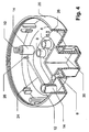
- Fig. 4 it shows a shell portion 20 which is one part of the plastic housing of a compact fluorescent lamp.
- the other part of the housing is a cap portion which will be described in the forthcoming figures.
- a socket (not shown) belongs to the lamp system generally including a ballast unit in the event of compact fluorescent lamps of plug-in type.
- the mechanical attach to the socket is established by a support plug 30 protruding from the bottom of the shell portion 20, while four contact pins 8 are provided for electrical connection towards the ballast unit.
- an electrical connector of the starting aid is represented by a contact wire 24 made of chrome-steel material.
- first end is attached to a contact pin 8, and its second end is formed as a helical spring 10 embedded in a nest 12 of a protrusion 14 extending from the bottom wall of the shell portion 20.
- a middle part of the contact wire 24 is led through plastic guides 26 from the contact pin 8 up to the protrusion 14. Only one contact wire 24 is shown in the figure, however a second one can also be disposed within the shell portion 20.
- the first end of the contact wire 24 together with a lead-in wire of an electrode will be crimped in a contact pin 8 connecting the electrical connector of the starting aid to the electrode of the lamp.
- the free end of the helical spring 10 will resiliently lean against one of the metallized electrodeless tube ends thereby pressing the second end of the contact wire 24 to an end portion of the electrodeless discharge tube.
- An effective capacitive coupling comes into being between the electrical connector of the starting aid and the discharge path point at the electrodeless tube end. Due to the effective capacitive coupling, an additional electrical potential is formed along the discharge path between the electrodes which modifies the breakdown path of the electrical field and reduces the starting voltage.
- Figs. 5 - 7 another embodiment of the starting aid is shown.
- the first end of the electrical connector is connected to the contact pin 8 and the second end is simply bent to form a wire spring 28.
- the middle portion is a contact wire 24 and is led through plastic guides 26 similarly to the previous embodiment.
- the wire spring 28 is nested in a plastic deflector 34 protruding from the bottom of the shell portion 20.
- the free end of the wire spring 28 will resiliently lean against one of the metallized electrodeless tube ends, while the first end of the contact wire 24 together with a lead-in wire of an electrode will be crimped in a contact pin 8 similarly to the embodiment according to Fig. 4 .
- the metallization of the tube ends can be made by a dabber print process or by sprinkling a paint containing a metal in a few microns of thickness.
- Fig. 5 two contact wires 24 with wire springs 28 are shown secured in place in the shell portion 20.
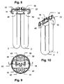
- FIG. 8 - 10 Another embodiment of the starting aid is shown in Figs. 8 - 10 .
- the discharge tube 2 is fixed in the cap portion 22 by the ends of the tube legs.
- the first and second electrode 40, 42 are inserted into two adjacent tube legs, the others are electrodeless tube legs 44, 46, 48, 54, 56, 58.
- the end portions of two electrodeless tube legs 46, 56 are metallized.
- a plastic support plate 18 including two leaf sprigs 16 is attached to the cap portion 22.
- the free ends of the leaf springs 16 lean resiliently against the ends of the metallized electrodeless discharge tube legs 46, 56 establishing an electrical connection with them.
- the other end thereof is pressed into the plastic support plate 18 and welded to a conductive wire which is connected to the electrodes and the contact pin of the shell portion illustrated in Fig. 4 during the lamp assembly process.
- Figs. 11 - 13 show a detailed structure of the plastic support plate 18 with the leaf spring 16.
- the plastic support plate 18 is secured in the cap portion of the lamp by ribs 32 protruding substantially parallel to a longitudinal axis of the lamp at an edge portion of the plastic support plate.
- the leaf springs 16 are inserted into the plastic support plate 18 by snapping one of their ends into the plastic support plate 18.
- the leaf springs 16 are made of resilient steel and serve as the second ends of the electrical connectors, the first ends of which correspond to the first ends of the conductive wires mentioned above.
- Insulators 6 protrude from the side of the plastic support plate 18 opposite to the tube ends in order to promote the insulation of the conducting elements mounted in the housing of the lamp.
- the spring portion of the electrical connector can be made of conductive sponge or rubber.
- Table 2 Type of starting aid It is seen in Starting voltage [Vrms] Starting aid connected to the tube end second from the electrodes, cross connection Fig. 1 555 Starting aid connected to the tube end first from the electrodes, cross connection Fig. 2 513 Starting aid connected to the tube ends first and second from the electrodes, cross connection Fig. 3 533
- the starting aid structure and the electrical cross-connection of its two electrical conductors according to the invention reduce the starting voltage of the fluorescent lamp significantly without decreasing the light output of the lamp and ensure safety against electric shock at the end of the life of the lamp.
- the two electrical conductors of the starting aid provide additional two discharge path points between the electrodes of the lamp.
- the voltage potential applied to the lamp electrodes is also applied to these additional discharge path points thereby modifying the breakdown path of the electrical field significantly.
- the springy structure of the electrical conductors of the starting aid ensures a firm capacitive coupling towards the discharge path thereby increasing the effectiveness of the additional discharge path points. An even more effective coupling is accomplished by the metallized end portion of the tube legs to which the electrical conductors are secured. Since the starting aid of the present invention is disposed in the plastic housing, it cannot cause dangerous electric shock and does not decrease the lumen output of the lamp.
Landscapes
- Fastening Of Light Sources Or Lamp Holders (AREA)
- Common Detailed Techniques For Electron Tubes Or Discharge Tubes (AREA)
Claims (12)
- Leuchtstofflampe mit Zündhilfe, wobei die Leuchtstofflampe eine Entladungsröhre (2) aus Glas umfasst, die einen Entladungsweg aufweist und gebogen ist, um eine Vielzahl von Entladungsröhrenarmen aufzuweisen, die sich in ein Plastikgehäuse erstrecken und dort fest angebracht sind; ferner eine erste und zweite Lampenelektrode, die sich an den jeweiligen Endpunkten eines Entladungswegs befinden, und wobei die Lampenelektroden mit Einrichtungen verbunden sind, die zur elektrischen Verbindung mit einer Fassung geeignet sind, gekennzeichnet durch
eine Zündhilfe, umfassend
einen in dem Plastikgehäuse angeordneten elektrischen Verbinder mit einem ersten und einem zweiten Ende, wobei das erste Ende mit der Einrichtung verbunden ist, die für die elektrische Verbindung mit einer der Lampenelektroden geeignet ist, und das zweite Ende an einem Endteil eines elektrodenlosen Entladungsröhrenarms (4, 44, 46, 48, 54, 56, 58) befestigt ist, und
zumindest ein Teil des elektrischen Verbinders als eine Feder ausgebildet ist. - Lampe nach Anspruch 1, wobei das Endteil des elektrodenlosen Entladungsröhrenarms (4, 44, 46, 48, 54, 56, 58), an dem das zweite Ende des elektrischen Verbinders befestigt ist, metallisiert ist.
- Lampe nach Anspruch 1, wobei die für die elektrische Verbindung mit einer Fassung geeignete Einrichtung ein Kontaktstift (8) ist.
- Lampe nach Anspruch 1, wobei der elektrische Verbinder ein Draht ist, der an seinem zweiten Ende gewunden ist, um eine spiralförmige Feder (10) zu bilden, um das genannte zweite Ende gegen das Endteil des elektrodenlosen Entladungsröhrenarms (4, 44, 46, 48, 54, 56, 58) zu pressen.
- Lampe nach Anspruch 4, wobei die spiralförmige Feder (10) sich in einer Hülle (12) befindet, die in einem Vorsprung (14) des Plastikgehäuses ausgebildet ist.
- Lampe nach Anspruch 3, wobei das erste Ende des elektrischen Verbinders an den Kontaktstift (8) angequetscht ist.
- Lampe nach Anspruch 1, wobei der elektrische Verbinder ein Draht ist, der mit einer Blattfeder (16) verbunden ist, die das zweite Ende des elektrischen Verbinders bildet, um das zweite Ende gegen das Endteil des elektrodenlosen Entladungsröhrenarms (4, 44, 46, 48, 54, 56, 58) zu pressen.
- Lampe nach Anspruch 7, wobei ein Ende der Blattfeder (16) an einer in dem Plastikgehäuse angeordneten Trägerplatte (18) befestigt ist.
- Lampe nach Anspruch 1, wobei das Plastikgehäuse ein Schalenteil (20) und ein Kappenteil (22) umfasst, die aneinander befestigt sind, und wobei die Entladungsröhrenarme an dem Kappenteil (22) befestigt sind und die für die elektrische Verbindung mit einer Fassung geeignete Einrichtung in dem Schalenteil (20) befestigt ist.
- Lampe nach einem der vorhergehenden Ansprüche, ferner ein Vorschaltgerät umfassend, das den von einer externen Energiequelle empfangenen elektrischen Strom steuert, wobei die Elektroden (40, 42) elektrisch mit dem Vorschaltgerät verbunden und in benachbarten Röhrenarmen der abgedichteten Lampeneinheit angeordnet sind und der elektrische Verbinder aufweist:einen ersten elektrischen Verbinder (36), der an einem Ende mit der ersten Lampenelektrode (40) verbunden und an einem anderen Ende zumindest an einem der Röhrenarme (46) befestigt ist, wobei dieser Röhrenarm auf dem Entladungsweg dem Röhrenarm, in dem die zweite Elektrode (42) angeordnet ist, in der Reihenfolge am nächsten liegt;einen zweiten elektrischen Verbinder (38), der an einem Ende mit der zweiten Lampenelektrode (42) verbunden und an einem anderen Ende zumindest an einem der Röhrenarme (56) befestigt ist, wobei dieser Röhrenarm auf dem Entladungsweg dem Röhrenarm, in dem die erste Elektrode angeordnet ist, in der Reihenfolge am nächsten liegt.
- Lampe nach Anspruch 10, wobei das andere Ende des ersten elektrischen Verbinders (36) zumindest an einem der Röhrenarme (44, 46, 48) befestigt ist, und wobei dieser Röhrenarm sich auf circa der Hälfte des Entladungswegs befindet und dem Röhrenarm, in dem die zweite Elektrode (42) angeordnet ist, in der Reihenfolge am nächsten liegt, und
wobei das andere Ende des zweiten elektrischen Verbinders (38) zumindest an einem der Röhrenarme (54, 56, 58) befestigt ist, und wobei dieser Röhrenarm sich auf circa der Hälfte des Entladungswegs befindet und dem Röhrenarm, in dem die erste Elektrode (40) angeordnet ist, in der Reihenfolge am nächsten liegt. - Lampe nach Anspruch 11, wobei das andere Ende des ersten elektrischen Verbinders (36) an dem ersten Röhrenarm (44) befestigt ist, der auf circa der Hälfte des Entladungswegs dem Röhrenarm, in dem die zweite Elektrode (42) angeordnet ist, in der Reihenfolge am nächsten liegt, und
wobei das andere Ende des zweiten elektrischen Verbinders (38) an dem ersten Röhrenarm (54) befestigt ist, der auf circa der Hälfte des Entladungswegs dem Röhrenarm, in dem die erste Elektrode (40) angeordnet ist, in der Reihenfolge am nächsten liegt.
Applications Claiming Priority (1)
| Application Number | Priority Date | Filing Date | Title |
|---|---|---|---|
| PCT/US2000/012978 WO2001087019A1 (en) | 2000-05-11 | 2000-05-11 | Starting aid for fluorescent lamps |
Publications (2)
| Publication Number | Publication Date |
|---|---|
| EP1293111A1 EP1293111A1 (de) | 2003-03-19 |
| EP1293111B1 true EP1293111B1 (de) | 2008-07-16 |
Family
ID=21741380
Family Applications (1)
| Application Number | Title | Priority Date | Filing Date |
|---|---|---|---|
| EP00932322A Expired - Lifetime EP1293111B1 (de) | 2000-05-11 | 2000-05-11 | Zündhilfe für leuchtstofflampen |
Country Status (3)
| Country | Link |
|---|---|
| EP (1) | EP1293111B1 (de) |
| DE (1) | DE60039541D1 (de) |
| WO (1) | WO2001087019A1 (de) |
Families Citing this family (1)
| Publication number | Priority date | Publication date | Assignee | Title |
|---|---|---|---|---|
| DE10306584A1 (de) | 2003-02-17 | 2004-08-26 | Patent-Treuhand-Gesellschaft für elektrische Glühlampen mbH | Niederdruckentladungslampe |
Family Cites Families (6)
| Publication number | Priority date | Publication date | Assignee | Title |
|---|---|---|---|---|
| US4853591A (en) * | 1983-11-25 | 1989-08-01 | Patent Treuhand Gesellschaft Fur Elektrische Gluhlampen Mbh | Multiple-tube compact low-pressure discharge fluorescent lamp |
| US5140221A (en) * | 1988-05-16 | 1992-08-18 | Seiko Epson Corporation | Rare gas cold cathode discharge tube and image input device |
| JPH067559Y2 (ja) * | 1988-06-20 | 1994-02-23 | 旭光学工業株式会社 | ランプの点灯構造 |
| DE3912514A1 (de) * | 1989-04-17 | 1990-10-18 | Imris Pavel | Leuchtstofflampe |
| US5289085A (en) * | 1992-10-16 | 1994-02-22 | Gte Products Corporation | Capacitively driven RF light source having notched electrode for improved starting |
| JPH07262970A (ja) * | 1994-03-24 | 1995-10-13 | Toshiba Lighting & Technol Corp | 低圧ガス放電ランプ、低圧ガス放電ランプ装置および照明装置 |
-
2000
- 2000-05-11 WO PCT/US2000/012978 patent/WO2001087019A1/en not_active Ceased
- 2000-05-11 EP EP00932322A patent/EP1293111B1/de not_active Expired - Lifetime
- 2000-05-11 DE DE60039541T patent/DE60039541D1/de not_active Expired - Lifetime
Also Published As
| Publication number | Publication date |
|---|---|
| WO2001087019A1 (en) | 2001-11-15 |
| DE60039541D1 (de) | 2008-08-28 |
| EP1293111A1 (de) | 2003-03-19 |
Similar Documents
| Publication | Publication Date | Title |
|---|---|---|
| CN1124639C (zh) | 高压放电灯 | |
| US4347460A (en) | Compact fluorescent lamp assembly | |
| WO1983004139A1 (en) | Flash lamp and circuitry for use with an incandescent light | |
| EP2227820B1 (de) | Kompakte leuchtstofflampe mit mechanischer unterstützung und starthilfe | |
| JPS60227337A (ja) | 片側差込式高圧放電灯 | |
| CN1188562A (zh) | 反光灯 | |
| US20090196029A1 (en) | Discharge lamp and fixture therefor | |
| EP0556800A1 (de) | Gasentladungslampe mit Löschmechanismus am Ende der Lebensdauer | |
| JP4610850B2 (ja) | 誘電体バリア放電ランプ | |
| US4422010A (en) | Shaped discharge lamp with starting aid | |
| EP1293111B1 (de) | Zündhilfe für leuchtstofflampen | |
| US7053553B1 (en) | Starting aid for fluorescent lamp | |
| US6429590B2 (en) | Straight fluorescent lamp with surface-mounted electrical conduit | |
| KR100521237B1 (ko) | 소형저압방전램프 | |
| CN100409400C (zh) | 低压气体放电灯 | |
| CN100530513C (zh) | 低压汞蒸气灯 | |
| JP4705806B2 (ja) | 誘電障壁放電ランプ | |
| US20060066245A1 (en) | Illumination system having a dielectric barrier discharge lamp and associated ballast | |
| KR20040020974A (ko) | 저압 가스 방전 램프 | |
| EP0583034B1 (de) | Elektrische Lampe | |
| WO2006075259A3 (en) | Lamp assembly comprising a uv-enhancer | |
| JPS60227377A (ja) | 片側差込式高圧放電灯のためのソケツト | |
| CN101416272A (zh) | 高压放电灯组件 | |
| US4144472A (en) | Glow discharge lamp | |
| JPH06132016A (ja) | 低圧放電灯及びそのための制御回路ハウジング |
Legal Events
| Date | Code | Title | Description |
|---|---|---|---|
| PUAI | Public reference made under article 153(3) epc to a published international application that has entered the european phase |
Free format text: ORIGINAL CODE: 0009012 |
|
| 17P | Request for examination filed |
Effective date: 20021211 |
|
| AK | Designated contracting states |
Kind code of ref document: A1 Designated state(s): AT BE CH CY DE DK ES FI FR GB GR IE IT LI LU MC NL PT SE |
|
| AX | Request for extension of the european patent |
Extension state: AL LT LV MK RO SI |
|
| RBV | Designated contracting states (corrected) |
Designated state(s): DE FR GB IT |
|
| 17Q | First examination report despatched |
Effective date: 20070129 |
|
| GRAP | Despatch of communication of intention to grant a patent |
Free format text: ORIGINAL CODE: EPIDOSNIGR1 |
|
| GRAS | Grant fee paid |
Free format text: ORIGINAL CODE: EPIDOSNIGR3 |
|
| GRAA | (expected) grant |
Free format text: ORIGINAL CODE: 0009210 |
|
| AK | Designated contracting states |
Kind code of ref document: B1 Designated state(s): DE FR GB IT |
|
| REG | Reference to a national code |
Ref country code: GB Ref legal event code: FG4D |
|
| REF | Corresponds to: |
Ref document number: 60039541 Country of ref document: DE Date of ref document: 20080828 Kind code of ref document: P |
|
| PLBE | No opposition filed within time limit |
Free format text: ORIGINAL CODE: 0009261 |
|
| STAA | Information on the status of an ep patent application or granted ep patent |
Free format text: STATUS: NO OPPOSITION FILED WITHIN TIME LIMIT |
|
| 26N | No opposition filed |
Effective date: 20090417 |
|
| PGFP | Annual fee paid to national office [announced via postgrant information from national office to epo] |
Ref country code: GB Payment date: 20130528 Year of fee payment: 14 Ref country code: DE Payment date: 20130530 Year of fee payment: 14 |
|
| PGFP | Annual fee paid to national office [announced via postgrant information from national office to epo] |
Ref country code: FR Payment date: 20130606 Year of fee payment: 14 Ref country code: IT Payment date: 20130525 Year of fee payment: 14 |
|
| REG | Reference to a national code |
Ref country code: DE Ref legal event code: R119 Ref document number: 60039541 Country of ref document: DE |
|
| GBPC | Gb: european patent ceased through non-payment of renewal fee |
Effective date: 20140511 |
|
| REG | Reference to a national code |
Ref country code: FR Ref legal event code: ST Effective date: 20150130 |
|
| REG | Reference to a national code |
Ref country code: DE Ref legal event code: R119 Ref document number: 60039541 Country of ref document: DE Effective date: 20141202 |
|
| PG25 | Lapsed in a contracting state [announced via postgrant information from national office to epo] |
Ref country code: DE Free format text: LAPSE BECAUSE OF NON-PAYMENT OF DUE FEES Effective date: 20141202 Ref country code: IT Free format text: LAPSE BECAUSE OF NON-PAYMENT OF DUE FEES Effective date: 20140511 |
|
| PG25 | Lapsed in a contracting state [announced via postgrant information from national office to epo] |
Ref country code: FR Free format text: LAPSE BECAUSE OF NON-PAYMENT OF DUE FEES Effective date: 20140602 Ref country code: GB Free format text: LAPSE BECAUSE OF NON-PAYMENT OF DUE FEES Effective date: 20140511 |