EP1295720B1 - Cylindre porte-plaque pour une machine à imprimer - Google Patents
Cylindre porte-plaque pour une machine à imprimer Download PDFInfo
- Publication number
- EP1295720B1 EP1295720B1 EP02019599A EP02019599A EP1295720B1 EP 1295720 B1 EP1295720 B1 EP 1295720B1 EP 02019599 A EP02019599 A EP 02019599A EP 02019599 A EP02019599 A EP 02019599A EP 1295720 B1 EP1295720 B1 EP 1295720B1
- Authority
- EP
- European Patent Office
- Prior art keywords
- clamping device
- shaft
- lever
- rear clamping
- plate cylinder
- Prior art date
- Legal status (The legal status is an assumption and is not a legal conclusion. Google has not performed a legal analysis and makes no representation as to the accuracy of the status listed.)
- Expired - Lifetime
Links
- 238000007639 printing Methods 0.000 title claims description 52
- 238000007645 offset printing Methods 0.000 claims description 2
- 230000008878 coupling Effects 0.000 description 9
- 238000010168 coupling process Methods 0.000 description 9
- 238000005859 coupling reaction Methods 0.000 description 9
- 238000001514 detection method Methods 0.000 description 8
- 239000011248 coating agent Substances 0.000 description 1
- 238000000576 coating method Methods 0.000 description 1
- 230000001419 dependent effect Effects 0.000 description 1
- 238000011161 development Methods 0.000 description 1
- 230000018109 developmental process Effects 0.000 description 1
- 230000007257 malfunction Effects 0.000 description 1
- 238000000034 method Methods 0.000 description 1
- 230000001960 triggered effect Effects 0.000 description 1
Images




Classifications
-
- B—PERFORMING OPERATIONS; TRANSPORTING
- B41—PRINTING; LINING MACHINES; TYPEWRITERS; STAMPS
- B41F—PRINTING MACHINES OR PRESSES
- B41F27/00—Devices for attaching printing elements or formes to supports
- B41F27/12—Devices for attaching printing elements or formes to supports for attaching flexible printing formes
- B41F27/1218—Devices for attaching printing elements or formes to supports for attaching flexible printing formes comprising printing plate tensioning devices
- B41F27/1225—Devices for attaching printing elements or formes to supports for attaching flexible printing formes comprising printing plate tensioning devices moving in the printing plate end substantially rectilinearly
- B41F27/1243—Devices for attaching printing elements or formes to supports for attaching flexible printing formes comprising printing plate tensioning devices moving in the printing plate end substantially rectilinearly by pivotal or swivelling motion, e.g. by means of a rocking lever
Definitions
- the invention relates to a forme cylinder for a printing press according to the preamble of claim 1.
- the printing plates are mounted on a plate cylinder and thereby secured to a respectively the leading and the trailing end of the printing plate associated clamping device.
- the clamping of the printing forme around the outer circumference of the forme cylinder takes place from the end of printing by exerting a tensile force.
- the actuation of the clamping devices of the forme cylinder takes place automatically in the case of automated printing form changers.
- the front and the rear clamping device is assigned in each case an actuating element, by which a printing forme can be clamped or released and tensioned from the end of the printing.
- Such a device is shown, for example, by EP 0 458 323 A1.
- both the clamping and clamping takes place via the rear clamping device by means of eccentric or cam arranged on two shafts.
- the clamping or releasing the leading edge of the printing form via the cams of the front clamping device associated shaft - the clamping and clamping on the rear clamping device also takes place via a shaft.
- a form cylinder for a printing machine in which the clamping of the leading edge of the printing form and the clamping and tensioning of the trailing, beveled end of a printing form via an actuator.
- This pressurizing acted upon actuating device acts on the front and rear clamping device associated spring elements, which are matched in their spring force to the corresponding pressures with which the actuator is to act.
- pressurization of the actuator causes clamping of the leading end of the printing form up to a first pressure value.
- increasing the pressure above a predetermined value then takes place the detection of the folded rear end of the printing form and the clamping of the printing plate on the pivotable clamping device.
- the spring elements associated with the individual clamping devices can be adapted exactly to pressure conditions with which the actuating element is to be controlled. If these pressure ratios are not maintained exactly - which can occur, for example, by a brief pressure loss - malfunctions can be triggered during the course of a printing plate change. This may then require time-consuming manual intervention.
- a disadvantage of several to be arranged in a cylinder actuators (motors) for clamping and clamping of printing plates is the space required for this. Especially with small cylinders or cylinders of small format printing presses the space available is relatively scarce - further weaknesses corresponding cavities in the cylinder body, the structure and the rigidity of the cylinder.
- Object of the present invention is therefore to develop a cylinder for a printing press according to the preamble of claim 1 such that, while avoiding the disadvantages mentioned above, a structurally simple and a safe process enabling device is created.
- the actuating element cooperates in a first movement phase with the front clamping device and in a further movement phase with the rear clamping device.
- the articulation of the adjusting element to the front or rear clamping device is such that the force applied by the actuator force acts exclusively on the front and the rear clamping device.
- the front and rear clamping device is actuated in each case via a shaft together with eccentric or cam attached thereto.
- the rear clamping device is pivotally mounted about the axis of this associated shaft.
- a radially movable lower part for clamping or releasing the printing form edge can be actuated.
- the inventively provided actuator now acts via a rotatably mounted with respect to the front shaft two-armed lever, one arm acts as a driver with two attached to the shaft or the eccentric attacks.
- a coupling this two-armed and directly driven by the actuator lever is connected to a mounted on the eccentric shaft of the rear clamping device lever, wherein via a further lever, the pivoting of the rear clamping device.
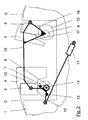
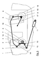
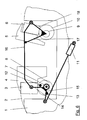
- Figures 1-7 show the invention acting on the front and the rear clamping device actuator.
- a front clamping device 3 for securing a leading end of a printing form 2 and a rear clamping device 3, 4, 5, 6 for securing the trailing end of a printing form 2 are provided in the form of a respective rail (FIG. 1).
- the front clamping device consists of a cylinder-fixed upper part 4 and a radially movable lower part 3.
- the rear clamping device is pivotally mounted about the axis of a shaft 9, the function of which is further explained below standing exactly.
- the pivotable upper part 5 acts to receive the end a printing form 2 with a radially movable lower part 6 together.
- a shaft 7 is rotatably mounted below this clamping device 3, 4, which has an eccentric 8.
- This eccentric 8 cooperates with the underside of the lower part 3 for opening and closing the end of the printing form 2 receiving detection area between the lower part 3 and upper part 4 together.
- a shaft 9 is rotatably mounted, which also has an eccentric 10. As already mentioned above, the rear clamping device 5, 6 is rotatably mounted about the axis of the shaft 9.
- a working cylinder 11 is shown in principle as an actuating element 11, which is considered to be effective when pressure medium is applied.
- Whose piston rod acts via a hinge on a lever 15 of a total two-armed lever 14, 15 which is rotatably mounted about the axis of the shaft 7.
- the lever 14 of this two-armed lever 14, 15 as ternary member are two stops 12, 13 associated with the eccentric 8, so that the lever 14 in a corresponding rotational movement in the counterclockwise direction ( Figure 1) entrains the eccentric 8.
- Figure 1 In a rotation of the lever 14 in a clockwise direction is rotated in this only to the free travel to the abutment against the stop 12, only then the eccentric 8 is taken in this direction.
- the lower part 3 is pressed into the corresponding surface of the upper part 4, that is, the detection area which receives the edge of the printing form 2 is closed.
- Fig. 1 shows the forme cylinder 1 with a through the front and the rear fastening means 3, 4; 5, 6 tensioned printing form 2.
- 6 is now pivoted by driving the actuating element 11 of the two-armed lever 14, 15 so that the lever arm 14 abuts against the stop 12 of the eccentric 8.
- 6 was pivoted such that the upper and lower part 5, 6 located detection area for the printing form 2 was opened.
- the actuating element 11 is now controlled such that the two-armed lever 14, 15 by abutment of the lever 14 on the stop 13, the eccentric 8 corresponding rotated (Fig. 4).
- the lower part 3 of the front clamping device 3, 4 thus moves down into the open position.
- this pivotal movement is transmitted to the two-armed lever 17, 18 of the rear clamping device 5, 6, but this causes only a pivoting movement of the shaft 9 of the eccentric 10.
- the rear clamping device 5, 6 is not shown by stop means already in the fully pivoted-back position (middle cylinder channel) and can not follow the movement of the two-armed lever 17, 18.
- the lower part 3 is in the lower position, ie a printing forme 2 can be introduced into the opened detection area (FIG. 5).
- the two-armed lever 14, 15 can be pivoted again in the clockwise direction until the lever 14 bears against the stop 12.
- the Angular position of the eccentric 8 and thus the position of the lower part 3 of the front clamping device 3, 4 remains unchanged.
- this movement has been transmitted only in a corresponding pivoting movement of the rear clamping device 5, 6 associated eccentric 10.
- the two-armed lever 14, 15 can again be pivoted counterclockwise by corresponding actuation of the actuating element 11 until the lever 14 abuts the stop 13 of the eccentric 8 (Fig. 7).
- this movement was in a pivotal movement of the two-armed lever 17, 18 of the shaft 9 of the rear clamping device 5, 6 transmitted, now by clamping the lever 17, the clamping device 5, 6 is pivoted back into the channel center and the trailing end of a printing plate 2 in the open detection area between the lower part 6 and upper part 5 can be listed.
Landscapes
- Engineering & Computer Science (AREA)
- Mechanical Engineering (AREA)
- Supply, Installation And Extraction Of Printed Sheets Or Plates (AREA)
- Feeding Of Articles By Means Other Than Belts Or Rollers (AREA)
- Printing Plates And Materials Therefor (AREA)
Claims (8)
- Cylindre porte-plaque pour une machine à imprimer, notamment dans des groupes d'impression ou de vernissage d'une machine d'impression offset à feuilles, comprenant un dispositif de serrage avant pour recevoir l'extrémité avant d'une plaque d'impression et un dispositif de serrage arrière pour recevoir l'extrémité arrière de la plaque d'impression ainsi qu'un actionneur pour actionner les dispositifs de serrage avant et arrière ainsi que pour serrer la plaque d'impression,
caractérisé en ce que
l'actionneur (11) permet d'actionner dans une première phase de déplacement exclusivement le dispositif de serrage arrière (5, 6) et dans une deuxième phase de déplacement le dispositif de serrage avant (3, 4). - Cylindre porte-plaque selon la revendication 1,
caractérisé en ce que
l'on associe au dispositif de serrage avant (3, 4) un excentrique (8) pouvant être actionné par le biais d'un arbre (7). - Cylindre porte-plaque selon la revendication 1 ou 2,
caractérisé en ce que
l'on associe au dispositif de serrage arrière (5, 6) un excentrique (10) pouvant être actionné par un arbre (9). - Cylindre porte-plaque selon l'une quelconque des revendications précédentes,
caractérisé en ce que
le dispositif de serrage arrière (5, 6) est monté de manière à pouvoir pivoter autour d'un axe s'étendant parallèlement à l'axe du cylindre porte-plaque (1). - Cylindre porte-plaque selon la revendication 4,
caractérisé en ce que
le dispositif de serrage arrière (5, 6) est monté de manière à pouvoir pivoter autour de l'axe de l'arbre (9). - Cylindre porte-plaque selon l'une quelconque des revendications précédentes,
caractérisé en ce qu'
un levier à deux bras (14, 15) est monté de manière à pouvoir tourner autour de l'axe de l'arbre (7), deux butées (12, 13) sur l'excentrique (8) lui étant associées. - Cylindre porte-plaque selon les revendications 2, 3 et 6,
caractérisé en ce que
l'on associe à l'arbre (9) du dispositif de serrage arrière (5, 6) un levier (18) qui est accouplé par le biais d'une bielle (16) à un levier (14) de l'arbre (7) du dispositif de serrage avant (3, 4). - Cylindre porte-plaque selon la revendication 7,
caractérisé en ce que
le dispositif de serrage arrière (5, 6) pouvant pivoter à l'encontre de la force de ressort peut être actionné par le biais d'un deuxième levier (17) monté sur l'arbre (9), en tant qu'élément d'entraînement.
Applications Claiming Priority (2)
| Application Number | Priority Date | Filing Date | Title |
|---|---|---|---|
| DE10146345A DE10146345B4 (de) | 2001-09-20 | 2001-09-20 | Klemm- und Spannvorrichtung für eine Druckmaschine |
| DE10146345 | 2001-09-20 |
Publications (2)
| Publication Number | Publication Date |
|---|---|
| EP1295720A1 EP1295720A1 (fr) | 2003-03-26 |
| EP1295720B1 true EP1295720B1 (fr) | 2006-07-05 |
Family
ID=7699662
Family Applications (1)
| Application Number | Title | Priority Date | Filing Date |
|---|---|---|---|
| EP02019599A Expired - Lifetime EP1295720B1 (fr) | 2001-09-20 | 2002-09-03 | Cylindre porte-plaque pour une machine à imprimer |
Country Status (3)
| Country | Link |
|---|---|
| EP (1) | EP1295720B1 (fr) |
| AT (1) | ATE332234T1 (fr) |
| DE (2) | DE10146345B4 (fr) |
Families Citing this family (2)
| Publication number | Priority date | Publication date | Assignee | Title |
|---|---|---|---|---|
| DE102004052823A1 (de) * | 2004-11-02 | 2006-05-04 | Koenig & Bauer Ag | Vorrichtung zum Klemmen und Spannen des nachlaufenden Endes einer Druckplatte |
| DE102020209465B3 (de) * | 2020-07-28 | 2021-07-15 | Heidelberger Druckmaschinen Aktiengesellschaft | Druckplatten-Greifsystem |
Family Cites Families (5)
| Publication number | Priority date | Publication date | Assignee | Title |
|---|---|---|---|---|
| US3359899A (en) * | 1965-02-01 | 1967-12-26 | Cottrell Company | Spring tensioned wrap-around plate cylinder clamping arrangement |
| JPS5766970A (en) * | 1980-10-15 | 1982-04-23 | Mitsubishi Heavy Ind Ltd | Tightener for plate |
| JP2509511Y2 (ja) * | 1990-05-25 | 1996-09-04 | 株式会社小森コーポレーション | 印刷機の版万力装置 |
| DE4306139C2 (de) * | 1993-02-27 | 1996-10-10 | Heidelberger Druckmasch Ag | Vorrichtung zur Durchführung von Arbeitsschritten in einem Zylinder einer Druckmaschine |
| DE29807377U1 (de) * | 1998-04-23 | 1998-07-16 | MAN Roland Druckmaschinen AG, 63075 Offenbach | Befestigungsvorrichtung für Platten auf Druckmaschinenzylindern |
-
2001
- 2001-09-20 DE DE10146345A patent/DE10146345B4/de not_active Expired - Fee Related
-
2002
- 2002-09-03 EP EP02019599A patent/EP1295720B1/fr not_active Expired - Lifetime
- 2002-09-03 DE DE50207428T patent/DE50207428D1/de not_active Expired - Lifetime
- 2002-09-03 AT AT02019599T patent/ATE332234T1/de active
Also Published As
| Publication number | Publication date |
|---|---|
| EP1295720A1 (fr) | 2003-03-26 |
| ATE332234T1 (de) | 2006-07-15 |
| DE10146345B4 (de) | 2006-07-06 |
| DE50207428D1 (de) | 2006-08-17 |
| DE10146345A1 (de) | 2003-04-24 |
Similar Documents
| Publication | Publication Date | Title |
|---|---|---|
| DE3940796C2 (fr) | ||
| EP0453845B1 (fr) | Machine à imprimer des feuilles en offset avec au moins un bloc d'impression | |
| DE8319431U1 (de) | Vorrichtung zur umstellung auf wahlweisen schoendruck oder schoen- und widerdruck einer zwischen den einzelnen druckwerken einer bogenrotationsdruckmaschine angeordneten wendeeinrichtung | |
| EP0736384B1 (fr) | Dispositif pour enclencher ou déclencher l'impression et procédé de contrÔle de ce dispositif | |
| EP0579002B1 (fr) | Procédé et dispositif pour la mise en/hors service du dispositif de retournement des feuilles lors de l'alimentation en feuilles dans une machine à imprimer | |
| EP1295720B1 (fr) | Cylindre porte-plaque pour une machine à imprimer | |
| EP0664213B1 (fr) | Procédé et dispositif pour exécuter des étapes de travail dans une machine à imprimer | |
| DE10111068A1 (de) | Walzenschloss zum lösbaren Befestigen einer Walze in einer Druckmaschine | |
| EP0631868B1 (fr) | Dispositif pour tendre en repérage des plaques d'impression sur les cylindres de machines d'impression | |
| EP0714768A1 (fr) | Dispositif d'accouplement d'une unité d'impression | |
| DE4424977A1 (de) | Bogenabweiser an bogenführenden Zylindern | |
| EP0425935B1 (fr) | Dispositif de mise en tension parallèle des plaques d'impression | |
| DE19505630A1 (de) | Vorrichtung zum Wechseln von Druckplatten | |
| DD229666B1 (de) | Steuereinrichtung fuer greifer eines vorgreifers an bogenverarbeitenden maschinen | |
| EP0786338B1 (fr) | Dispositif pour la mise en pression et hors pression d'un cylindre | |
| DE19753820A1 (de) | Vorrichtung zum gegenseitigen Anstellen von Druckwerkzylindern | |
| DE10052354B4 (de) | Vorrichtung zur Druckan- und Druckabstellung eines Gummizylinders zu einem Plattenzylinder und einem Gegendruckzylinder | |
| DE4335185A1 (de) | Einrichtung zum Betätigen von Saugluftsteuerelementen | |
| EP1609598B1 (fr) | Procédé d'entrainement sécurisé d'une machine d'impression et machine d'impression mettant en oeuvre ce procédé | |
| DE4315905C2 (de) | Klemm- und Spanneinrichtung für eine Druckmaschine | |
| EP1712359B1 (fr) | Dispositif et procédé pour presser un cliché contre un cylindre d'impression d'une presse rotative | |
| DE4223328C2 (de) | Vorrichtung zum Befestigen von Druckplatten auf dem Plattenzylinder von Druckmaschinen, insbesondere Bogenoffsetdruckmaschinen | |
| EP2110246B1 (fr) | Dispositif de changement de plaque d'impression | |
| EP3546215B1 (fr) | Dispositif pour fixer des plaques d'impression sur un cylindre porte-plaque | |
| EP1297955B1 (fr) | Dispositif pour la fixation d'un cliché d'impression |
Legal Events
| Date | Code | Title | Description |
|---|---|---|---|
| PUAI | Public reference made under article 153(3) epc to a published international application that has entered the european phase |
Free format text: ORIGINAL CODE: 0009012 |
|
| 17P | Request for examination filed |
Effective date: 20021207 |
|
| AK | Designated contracting states |
Designated state(s): AT BE BG CH CY CZ DE DK EE ES FI FR GB GR IE IT LI LU MC NL PT SE SK TR Kind code of ref document: A1 Designated state(s): AT BE BG CH CY CZ DE DK EE ES FI FR GB GR IE IT LI LU MC NL PT SE SK TR |
|
| AX | Request for extension of the european patent |
Extension state: AL LT LV MK RO SI |
|
| AKX | Designation fees paid |
Designated state(s): AT DE FR GB |
|
| GRAP | Despatch of communication of intention to grant a patent |
Free format text: ORIGINAL CODE: EPIDOSNIGR1 |
|
| GRAS | Grant fee paid |
Free format text: ORIGINAL CODE: EPIDOSNIGR3 |
|
| GRAA | (expected) grant |
Free format text: ORIGINAL CODE: 0009210 |
|
| AK | Designated contracting states |
Kind code of ref document: B1 Designated state(s): AT DE FR GB |
|
| PG25 | Lapsed in a contracting state [announced via postgrant information from national office to epo] |
Ref country code: GB Free format text: LAPSE BECAUSE OF FAILURE TO SUBMIT A TRANSLATION OF THE DESCRIPTION OR TO PAY THE FEE WITHIN THE PRESCRIBED TIME-LIMIT Effective date: 20060705 |
|
| REG | Reference to a national code |
Ref country code: GB Ref legal event code: FG4D Free format text: NOT ENGLISH |
|
| REF | Corresponds to: |
Ref document number: 50207428 Country of ref document: DE Date of ref document: 20060817 Kind code of ref document: P |
|
| GBV | Gb: ep patent (uk) treated as always having been void in accordance with gb section 77(7)/1977 [no translation filed] |
Effective date: 20060705 |
|
| EN | Fr: translation not filed | ||
| PLBE | No opposition filed within time limit |
Free format text: ORIGINAL CODE: 0009261 |
|
| STAA | Information on the status of an ep patent application or granted ep patent |
Free format text: STATUS: NO OPPOSITION FILED WITHIN TIME LIMIT |
|
| 26N | No opposition filed |
Effective date: 20070410 |
|
| PG25 | Lapsed in a contracting state [announced via postgrant information from national office to epo] |
Ref country code: FR Free format text: LAPSE BECAUSE OF FAILURE TO SUBMIT A TRANSLATION OF THE DESCRIPTION OR TO PAY THE FEE WITHIN THE PRESCRIBED TIME-LIMIT Effective date: 20070511 |
|
| PG25 | Lapsed in a contracting state [announced via postgrant information from national office to epo] |
Ref country code: FR Free format text: LAPSE BECAUSE OF FAILURE TO SUBMIT A TRANSLATION OF THE DESCRIPTION OR TO PAY THE FEE WITHIN THE PRESCRIBED TIME-LIMIT Effective date: 20060705 |
|
| PGFP | Annual fee paid to national office [announced via postgrant information from national office to epo] |
Ref country code: AT Payment date: 20100914 Year of fee payment: 9 |
|
| PGFP | Annual fee paid to national office [announced via postgrant information from national office to epo] |
Ref country code: DE Payment date: 20110923 Year of fee payment: 10 |
|
| REG | Reference to a national code |
Ref country code: DE Ref legal event code: R081 Ref document number: 50207428 Country of ref document: DE Owner name: MANROLAND SHEETFED GMBH, DE Free format text: FORMER OWNER: MANROLAND AG, 63075 OFFENBACH, DE Effective date: 20120509 |
|
| REG | Reference to a national code |
Ref country code: AT Ref legal event code: MM01 Ref document number: 332234 Country of ref document: AT Kind code of ref document: T Effective date: 20110903 |
|
| PG25 | Lapsed in a contracting state [announced via postgrant information from national office to epo] |
Ref country code: AT Free format text: LAPSE BECAUSE OF NON-PAYMENT OF DUE FEES Effective date: 20110903 |
|
| PG25 | Lapsed in a contracting state [announced via postgrant information from national office to epo] |
Ref country code: DE Free format text: LAPSE BECAUSE OF NON-PAYMENT OF DUE FEES Effective date: 20130403 |
|
| REG | Reference to a national code |
Ref country code: DE Ref legal event code: R119 Ref document number: 50207428 Country of ref document: DE Effective date: 20130403 |